US1852298A - Adjustable supporter for wire stitching machines - Google Patents
Adjustable supporter for wire stitching machines Download PDFInfo
- Publication number
- US1852298A US1852298A US505099A US50509930A US1852298A US 1852298 A US1852298 A US 1852298A US 505099 A US505099 A US 505099A US 50509930 A US50509930 A US 50509930A US 1852298 A US1852298 A US 1852298A
- Authority
- US
- United States
- Prior art keywords
- supporter
- staple
- movement
- screw
- stroke
- Prior art date
- Legal status (The legal status is an assumption and is not a legal conclusion. Google has not performed a legal analysis and makes no representation as to the accuracy of the status listed.)
- Expired - Lifetime
Links
- 230000033001 locomotion Effects 0.000 description 40
- 230000008933 bodily movement Effects 0.000 description 5
- 230000001276 controlling effect Effects 0.000 description 3
- 230000035939 shock Effects 0.000 description 3
- 241000269788 Sparidae Species 0.000 description 1
- 230000003111 delayed effect Effects 0.000 description 1
- 239000010985 leather Substances 0.000 description 1
- 235000019129 pluma Nutrition 0.000 description 1
- 235000019070 pluma del Caribe Nutrition 0.000 description 1
- 235000020004 porter Nutrition 0.000 description 1
- 230000001105 regulatory effect Effects 0.000 description 1
- 230000000284 resting effect Effects 0.000 description 1
- 239000011435 rock Substances 0.000 description 1
- 239000007779 soft material Substances 0.000 description 1
Images
Classifications
-
- B—PERFORMING OPERATIONS; TRANSPORTING
- B31—MAKING ARTICLES OF PAPER, CARDBOARD OR MATERIAL WORKED IN A MANNER ANALOGOUS TO PAPER; WORKING PAPER, CARDBOARD OR MATERIAL WORKED IN A MANNER ANALOGOUS TO PAPER
- B31B—MAKING CONTAINERS OF PAPER, CARDBOARD OR MATERIAL WORKED IN A MANNER ANALOGOUS TO PAPER
- B31B50/00—Making rigid or semi-rigid containers, e.g. boxes or cartons
- B31B50/60—Uniting opposed surfaces or edges; Taping
- B31B50/68—Uniting opposed surfaces or edges; Taping by stitching, stapling or riveting
Definitions
- This invention relates to wire .stitching machines and particularly, to that type wherein a wire staple, which is formed by the machine, rests upon a staple supported prior to, and
- My invention is directed, particularly, to the staple supporter, and contemplates the provision of means for adjusting the extent of the movement of said supporter, so that only that portion thereof is used, which is necessary for the stitching operation.
- the stroke or extent of the movement of the staple supporter is always the same, regardless of the length of the particular staple formed and driven by the machine. This results in noisy operation and unnecessary wear on the drive mechanism for the supporter,
- My invention makes it possible to avoid the above-mentioned disadvantages in constant stroke supporters, by providing means for adjusting said stroke within the necessary practical limits. I prefer to do this by regulating the forward limiting position of the staple supporter preferably without changing the extreme retracted or rearward position thereof.
- Fig. 1 is a side elevation of part of a wire stitching machine, showing my new adjusting means applied thereto and showing the supporter in its fully retracted' position.
- Fig. 2 is a similar view of the same, showing the supporter in its partly extended position wherein its limiting forward position has been adjusted, so that it is not projected as far as possible, and showing in dotted lines the position of the parts when the supporter is adjusted for greater forward movement,
- ⁇ and Fig. 3 is a rear view of my new adjusting mechanism.
- the usual reciprocating staple guide slide 10 is provided.
- Said guide slide is suitably reciprocated in the front block 11 30 in the usual manner, as by means of the pin 12, which is operated by the usual revoluble cam as 50 through the drive shaft 51 in a well known manner and hence which need not be further described.
- the reciprocating staple driver 13 is mounted in the guide slide 12 for vertical reciprocation in the usual manner, and is operated by the crank 14 through the pin 15, which in turn is inserted in a suitable groove in said cam ⁇ 50 in a man- 90 ner well known in the art.
- At the lowerend of the guide slide is secured the hollow guide block 16 for the rocking staple supporter 17.
- the inner surface 18 of said block is curved arcuately to correspond with the lower conveX surface 19 of the supporter.
- the upper surface of the supporter is concave, and intersects the lower surface 19 to form the front edge of the supporter. Said supporter swings, rocks, or oscillates into and out of the block 16, being guided in its rocking movement by the block 16.
- a pin as 20 passes therethrough and through the arcuate slots 21 in the side walls 22 of the block 16.
- the pin 20 is provided with the spring-supporting pins 24, about each of which al spring 25 is arranged.
- Into the lower end of each of the. springs 25, is inserted a similar supporting pin 26, which is secured to one of the levers 27 at 28.
- Each of said levers 27, is pivoted to the block 16 as by means of the pivot 29.
- Said means comprises the relatively lixed bearing 30 secured to the rear part of the main frame as by means of the bolt 31, and having the adjusting screw 32 Yloosely passed therethrough.
- the adjusting screw is secured to the member 33, ⁇ which is in turn supported by the shaft 34, suitably connected to the levers 27.
- the pair of adjusting stop nuts and 36 are arranged preferably with the lock washer 38 therebetween.
- a cushioning washer as 39 made of leather, rubber, or similar comparatively soft material is preferably interposed between the lower nut 36 and the top of the bearing 30, to take up or cushion the shock when the nut 36 is drawn down thereon on the downward movement of the screw 32.
- a spring as 40 abuts against the member 33 at one end, and at its other end, is in- Serted into the enlargedV opening 41 of the bearing 30.
- the driver 13 may now move downwardly to engage and drive the staple.
- the driver engages the concave surface of the supporter, and owing to y the cam action therebetween, causes retraction of thel supporter 17 into the block 16, the pin 2O moving upwfrdly in the slots 21, until' it engages the end of the slot.
- the shaft 34 may also move upwardly to some extent, thereby moving the screw 32 bodily through the bearing 30, and ifso moved to a sufficient extent, lifting the nut 36 off the washer39.
- the position of the adjusting nuts 35 and 36 on the adjusting screw 32 determines the point in the cam slots 21, at which the pin 20 will stop on the downward movement of the staple guide slide 10, and hence determines how far the supporter 17 is moved forwardly. In other words, when the adjusting nuts are at their lowermost positions on the screw 37, the stroke of the supporter 17 is the maximum,
- the stroke of the supporter is least. Intermediate positions of the adjusting nuts will correspondingly vary the stroke of the supporter between the innermost and' outermost limits of the end of the for! ward stroke, but the limit of the rearward stroke preferably remainsthe same.
- the forward limit of the support-er stroke can be adjusted to the length of the staples to be driven so that staples of different lengths contact with the supporter surface 43 at different points, thereby preventing the wear which would occur on said surface if the stroke of the sup-- porter were always constant or independent of the length of the staples. It will also he seen that by adjusting the forward limiting position of the supporter, thin paper is not likely to be crushed or damaged by the supporter, and the free edges of the leaves of manifolding books need never come in cont-act with the supporter on its forward stroke and thus damage thereto is avoided, and raising of the supporter ofl" the work, and consequently possibility of buckling the staple is also avoided.
- a staple supporter having a wedge-shaped front end adapted to support a formed staple while the staple is being driven by the machine, means for projecting said supporter forwardly, and adjustable means for limiting the forward position of said end to bring a predetermined part of said end into operation including an adjustable lever yieldingly connected to the supporter.
- a staple supporter movable in an arcuate path, and means for adjusting the extent of the movement of the supporter including a screw operatively connected to the supporter and movable independently thereof, and means fory varying-the effective length of the screw.
- a staple supporter movable in an arcuate path, and means for varying the forward limit of said path including an adjusting screw operatively connected to the supporter, and adjustable stop means on the screw for determining the effective length of the screw.
- a. hollow block having a pair of aligned arcuate slots in the side walls thereof, means for vertically reciprocating said block, a staple supporter inserted into said block for movement into and out of the block, a pin at the upper end of said supporter passing through said slots for limiting the rearward movement of the supporter, and means for varying the limit of the forward movement of the supporter, including an adjusting screw operatively connected to thepin. and adjustable stop means on the screw for determining the effective length of said screw.
- means for driving a staple a staple supporter adapted to support a staple during the driving operation of the staple driving means, means for rocking said supporter, and means including an adjustable screw yieldingly connected to the supporter for varying the extent of the rocking movement of the supporter.
- a rocking staple supporter having an arcuate upper surface and an intersecting arcuate lower surface, and upright side walls joining said surfaces for supporting staples of different heights
- means including a reciprocatory guide block in which the supporter is inserted for rocking the supporter forwardly supporter, a reciprocatory guide block for the supporter, operatively connected to the supporter for rocking the supporter forwardly onV the downward movement of the block, and means for varying the limit of the forward rocking movement of the supporter independently of the movement of the block.
- a rocking staple supporter In a wire stitching machine, a rocking staple supporter, reciprocatory guide 1 means for the supporter for fixing the limit of the rearward rocking movement of the supporter and for rockingV said supporter forwardly on the downward movement of said means, and means for varying thestrolre of the supporter by determining the limit'of the forward rocking movement thereof.
- a forwardly and rearwardly rocking staple supporter means for guiding said supporter in its rocking movement including a guide having an arcuate slot therein, and a pin at the upper end of the supporter entering said slot, and means for varying the stroke of the supporter including adjustable stop means operatively connected to the pin for determining the forward limiting position of the supporter.
- a staple supporter mounted for rocking movement forwardly and rearwardly, a guide for the supporter having an arcuate slot therein, a member on the supporter entering said slot and guided thereby, the most rearward position of the supporter being determined by the engagement of said member with one end of said slot, and means for determining the limiting forward position of the supporter, comprising means for adjusting the extent of the movement of said pin from the aforementioned end of the slot.
- a staple supporter mounted for rocking movement forwardly and rearwardly, afreciprocating ⁇ guide for the supporter having a slot therein,
- a staple supporter mounted for forward and rearward rocking movement, a slotted guide for the supporter, a guide member on the supporter entering the slot of the guide, and
- means for controlling the amount which the Y J movement, and means for controlling the extent of the forward movement of the supporter comprising an adjusting screw operatively connected to the supporter and mounted for bodily movement, a relatively fixed bearing for loosely supporting said screw, and adjustable stop means on the screw for limiting the movement of said screw through the bearing in one direction and thereby limiting the forward movement of the supporter.
- a staple supporter adapted to support a staple while the staple is being driven by the machine, means for moving said supporter alternately in opposite directions, and means for controlling the'extent of the movement of the supporter in one direction, comprising a bodily movable .member operatively vconnected at one end thereof to and movable independently of the supporter, and adjustable stop means on the member for limiting the extent of the bodily movement of the member in one direction.
- a staple supporter mounted for forward and rearward rocking movement, and having flat, up-
- a hollow reciprocating block for the supporter having aligned slots in the side walls thereof, a pin connected to the supporter and entering said slots, a pair of spaced levers pivoted to the block below the lower ends of the slots, springs connecting the forward ends of the levers with the corresponding endsof the pin, an adjusting screw operatively connected at Vits lower end to the rear ends of the levers, a relatively fixed bearing through which said screw is passed for bodily movement therein, and adjustable stops on the screw forengaging said bearing on the downward bodily movement of the screw and thereby halting the forward movement of the supporter.
- a swingable staple supporter and means for limiting the extent of the forward movement of the supporter independently of the limit of the rearward movement thereof, comprising a bodily movable member operatively connected to the supporter at its lower end, a relatively xed bearing loosely carrying said member, an adjustable stop on the member above the bearing, and a cushioning member interposed between the stop and the bearing engageable by the stop for halting the bodily movement of the member in one direction.
Landscapes
- Portable Nailing Machines And Staplers (AREA)
Description
T. A. GIBSON ADJUSTABLE SUPPORTER FOR WIRE STITCHING MACHINES" Filed Dec. 27, 1930 iilll';
IN V NTQR Plumas/1. @Ibsen ATTORNEY Patented Apr. 5, 1932 PATENT OFFICE THOMAS A. GIBSON, OF BROOKLYN, NEW YORK ADJUSTABLE SUPPORTER FOR WIRE STITCHING MACHINES Application iled December 27, 1930. Serial No. 505,099.
This invention relates to wire .stitching machines and particularly, to that type wherein a wire staple, which is formed by the machine, rests upon a staple supported prior to, and
during the staple driving or stitching operation.
My invention is directed, particularly, to the staple supporter, and contemplates the provision of means for adjusting the extent of the movement of said supporter, so that only that portion thereof is used, which is necessary for the stitching operation. In wire stitching machines heretofore known, the stroke or extent of the movement of the staple supporter is always the same, regardless of the length of the particular staple formed and driven by the machine. This results in noisy operation and unnecessary wear on the drive mechanism for the supporter,
which mechanism .strikes the end of a guide slot at each end of the stroke. If thin paper is to be stitched7 a further difliculty in previously known machines is that the supporter in its forward' movement frequently damages such paper, owing to the unnecessary length of said stroke, and the consequent Contact of the supported with the paper and its movement thereover.
In cases where manifolding books are to be stitched, such books frequently contain pages which are folded in such a manner that the ends of the pages just in front of the stitching point of the machine, form a much greater thickness than at the point where the book is to be stitched. When the supporter moves forward, therefore, it frequently strikes the free ends of the folded pages and throws them out of position and damages the pages or the book, owing to the excessiveiy long stroke of the supporter. It further frequently happens that the end of the supporter rides up on the thicker folded pages of such books, and hence is raised up off the work to be stitched. The staple supported is thereby unable to perform its function properly, .since it is raised out of position, and cannot support the lower part of the staple, which frequently buckles when driven into the work under these conditions.
My invention makes it possible to avoid the above-mentioned disadvantages in constant stroke supporters, by providing means for adjusting said stroke within the necessary practical limits. I prefer to do this by regulating the forward limiting position of the staple supporter preferably without changing the extreme retracted or rearward position thereof.
The various objects of my invention will be clear from the description which follows, and from the drawings, in which,
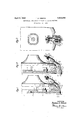
Fig. 1 is a side elevation of part of a wire stitching machine, showing my new adjusting means applied thereto and showing the supporter in its fully retracted' position. 65
Fig. 2 is a similar view of the same, showing the supporter in its partly extended position wherein its limiting forward position has been adjusted, so that it is not projected as far as possible, and showing in dotted lines the position of the parts when the supporter is adjusted for greater forward movement,
` and Fig. 3 is a rear view of my new adjusting mechanism.
In that practical embodiment of my invention which I have illustrated by way of eX- ample, the usual reciprocating staple guide slide 10 is provided. Said guide slide is suitably reciprocated in the front block 11 30 in the usual manner, as by means of the pin 12, which is operated by the usual revoluble cam as 50 through the drive shaft 51 in a well known manner and hence which need not be further described. The reciprocating staple driver 13 is mounted in the guide slide 12 for vertical reciprocation in the usual manner, and is operated by the crank 14 through the pin 15, which in turn is inserted in a suitable groove in said cam`50 in a man- 90 ner well known in the art. At the lowerend of the guide slide is secured the hollow guide block 16 for the rocking staple supporter 17. The inner surface 18 of said block is curved arcuately to correspond with the lower conveX surface 19 of the supporter.
The upper surface of the supporter is concave, and intersects the lower surface 19 to form the front edge of the supporter. Said supporter swings, rocks, or oscillates into and out of the block 16, being guided in its rocking movement by the block 16. Preferably, near the upper end of said supporter, a pin as 20 passes therethrough and through the arcuate slots 21 in the side walls 22 of the block 16. At each of its ends, the pin 20 is provided with the spring-supporting pins 24, about each of which al spring 25 is arranged. Into the lower end of each of the. springs 25, is inserted a similar supporting pin 26, which is secured to one of the levers 27 at 28. Each of said levers 27, is pivoted to the block 16 as by means of the pivot 29.
The means for adjusting the most forwardly position of the supporter will now be described. Said means comprises the relatively lixed bearing 30 secured to the rear part of the main frame as by means of the bolt 31, and having the adjusting screw 32 Yloosely passed therethrough. A t its lower end, the adjusting screw is secured to the member 33,` which is in turn supported by the shaft 34, suitably connected to the levers 27. At the upper threaded end V37 of the v screw 32, the pair of adjusting stop nuts and 36 are arranged preferably with the lock washer 38 therebetween. As indicated by the different positions of the screw 32 in Figs. 1 and 2, said screw moves bodily `through the bearing 30 on the reeiprocation of the block 16, but its movement downwardly is halted by the st-op nuts.
A cushioning washer as 39, made of leather, rubber, or similar comparatively soft material is preferably interposed between the lower nut 36 and the top of the bearing 30, to take up or cushion the shock when the nut 36 is drawn down thereon on the downward movement of the screw 32.
To urge the screw toward that position thereof in which it is adjusted by the nuts 35 and 36, a spring as 40 abuts against the member 33 at one end, and at its other end, is in- Serted into the enlargedV opening 41 of the bearing 30.
It will be seen that as the staple guide is reciprocated through its downward stroke, the block 16 being secured thereto, moves with it, thereby carrying downwardly, the pivot shaft 29 and the shaft or pin 34. It willbe understood that at the beginning of this movement, the nuts 35 and 36 may have been .lifted off the washer 39, (asin 1) depending` on the adjustment thereof, and that the supporter 1'? in its retracted osition to which it has 7 been moved by the driver -13 as will be later described. At the first part of the movement, therefore, the shaft 34, together with the T here* screw 32 and of the shaft 34 is prevented. Asv the pivot 29 is carried down further, the levers 27 are rotated in a counterclock-wise i ldirection about the shaft 34. Such rotation puts tension upon the springs 25, thereby drawing down the pin 20 along the cam slots 21 and consequently sliding the supporter in a clock-wise direction against the surface 19. It will be seen, therefore, that on the downward movement of the staple guide slide 10, the. supporter is projected' forwardly of the machine into the proper position and to the desired extent to receive the staple previously arranged in the staple groove 42 by means .well known in the art. The prongs of the staple are arranged acent the upright sides ofthe supporter, while the cross bar rests in the concave surface 43.
The driver 13 may now move downwardly to engage and drive the staple. During the driving operation, the driver engages the concave surface of the supporter, and owing to y the cam action therebetween, causes retraction of thel supporter 17 into the block 16, the pin 2O moving upwfrdly in the slots 21, until' it engages the end of the slot.
Thereafter, on` upward movement of the slide 10, and consequently of the block 16 and of the pivot 29 the shaft 34 may also move upwardly to some extent, thereby moving the screw 32 bodily through the bearing 30, and ifso moved to a sufficient extent, lifting the nut 36 off the washer39.
The position of the adjusting nuts 35 and 36 on the adjusting screw 32 determines the point in the cam slots 21, at which the pin 20 will stop on the downward movement of the staple guide slide 10, and hence determines how far the supporter 17 is moved forwardly. In other words, when the adjusting nuts are at their lowermost positions on the screw 37, the stroke of the supporter 17 is the maximum,
tions on the screw, the stroke of the supporter is least. Intermediate positions of the adjusting nuts will correspondingly vary the stroke of the supporter between the innermost and' outermost limits of the end of the for! ward stroke, but the limit of the rearward stroke preferably remainsthe same.
In the. full-line positions of the parts shown in Fig. 2, the supporter 17 has been moved out as far as it can go, the driver 13 at this. time beingk in its raised position ready to be low-` ered te engage the formed staple now resting' on the supporter. and to drive the formed staple into the work while simultaneously re-g. tracting the supporter during` the drivingv operation. The dotted line position of the parts indicates that the nuts 35 and 36 have been turned down toward the lower end of the screw, whereby the forward stroke of the sunporter has been increased, as for example, when staples are to be driven through a thicker stack. j
After the staple has been driven through the stack, it will be understood that the staple supporter' remains in the retracted position into which it has been forced by the driver 13.
Vand when the nuts are at their highest posif It will also be understood that the guide 10 moves upwardly through part of its stroke while the driver 13 remains down and in front of the supporter, whereby the supporter remains retracted throughout the upward stroke of the guide 10 and that upward movement of the guide 10 and consequently, of the block 16 carries the supporter upwardly with it, and may also force the adjusting screw through and beyond the bearing 30, so that said screw may project beyond the bearing in the uppermost position of the slide. When the guide 10 has reached its uppermost position, the driver 13 is also in its upper position and clear ofthe supporter as will be seen from Fig. 2, the supporter being ready to be moved forwardly on the next downward movement of the guide 10, as has been above explained. It will be seen that the beginning of the forward stroke of the supporter 17 is delayed for a period, depending on how near the adjusting nuts are to the end of the screw 32.
The nearer the nuts are to said end, the longer will it take for the supporter to begin its forward stroke and therefore, the shorter will be its complete stroke and the less distance will it be forwardly projected. It will further be seen that only the full forward stroke of the supporter allows the pin 20 to strike the lowermost ends of the slots 21. In machines heretofore in general use, where the supporter stroke is always the full stroke, this results in considerable unnecessary wear and shock on the machine parts, which I have avoided. If the slots 21 are made of sufficient length, it therefore becomes entirely unnecessary for the pin 20 to reach the lowermost en ds of the slots at any time.
Furthermore, the forward limit of the support-er stroke can be adjusted to the length of the staples to be driven so that staples of different lengths contact with the supporter surface 43 at different points, thereby preventing the wear which would occur on said surface if the stroke of the sup-- porter were always constant or independent of the length of the staples. It will also he seen that by adjusting the forward limiting position of the supporter, thin paper is not likely to be crushed or damaged by the supporter, and the free edges of the leaves of manifolding books need never come in cont-act with the supporter on its forward stroke and thus damage thereto is avoided, and raising of the supporter ofl" the work, and consequently possibility of buckling the staple is also avoided.
It will further be seen that the use of the cushioning washer 39 absorbs the shock due to the drawing of the adjusting nuts downwardly toward the bearing 30, and that the operation of this part of the mechanism eliminates much of the noise which would otherwise be caused by the striking of the pin 20 against the ends of the guide slots.
While `I have shown and described a preferred embodiment of my invention, I do not wish to be understood as limiting myself thereto but intend to claim my invention as broadly as may be permitted by the state of the prior art and the terms of the appended claims.
I claim:
1. In a wire stitching machine, a staple supporter having a wedge-shaped front end adapted to support a formed staple while the staple is being driven by the machine, means for projecting said supporter forwardly, and adjustable means for limiting the forward position of said end to bring a predetermined part of said end into operation including an adjustable lever yieldingly connected to the supporter.
2. In a wire stitching machine, a staple supporter movable in an arcuate path, and means for adjusting the extent of the movement of the supporter including a screw operatively connected to the supporter and movable independently thereof, and means fory varying-the effective length of the screw.
3. In a wire stitching machine, a staple supporter movable in an arcuate path, and means for varying the forward limit of said path including an adjusting screw operatively connected to the supporter, and adjustable stop means on the screw for determining the effective length of the screw.
4. In a wire stitching machine, a. hollow block having a pair of aligned arcuate slots in the side walls thereof, means for vertically reciprocating said block, a staple supporter inserted into said block for movement into and out of the block, a pin at the upper end of said supporter passing through said slots for limiting the rearward movement of the supporter, and means for varying the limit of the forward movement of the supporter, including an adjusting screw operatively connected to thepin. and adjustable stop means on the screw for determining the effective length of said screw.
5. In a wire stitching machine, means for driving a staple, a staple supporter adapted to support a staple during the driving operation of the staple driving means, means for rocking said supporter, and means including an adjustable screw yieldingly connected to the supporter for varying the extent of the rocking movement of the supporter.
6. In a wire stitching machine, a rocking staple supporter having an arcuate upper surface and an intersecting arcuate lower surface, and upright side walls joining said surfaces for supporting staples of different heights, means including a reciprocatory guide block in which the supporter is inserted for rocking the supporter forwardly supporter, a reciprocatory guide block for the supporter, operatively connected to the supporter for rocking the supporter forwardly onV the downward movement of the block, and means for varying the limit of the forward rocking movement of the supporter independently of the movement of the block. i
8'. In a wire stitching machine, a rocking staple supporter, reciprocatory guide 1 means for the supporter for fixing the limit of the rearward rocking movement of the supporter and for rockingV said supporter forwardly on the downward movement of said means, and means for varying thestrolre of the supporter by determining the limit'of the forward rocking movement thereof.
9. Ina wire stitching machine, a forwardly and rearwardly rocking staple supporter, means for guiding said supporter in its rocking movement including a guide having an arcuate slot therein, and a pin at the upper end of the supporter entering said slot, and means for varying the stroke of the supporter including adjustable stop means operatively connected to the pin for determining the forward limiting position of the supporter.
10. In a Wire stitching machine, a staple supporter mounted for rocking movement forwardly and rearwardly, a guide for the supporter having an arcuate slot therein, a member on the supporter entering said slot and guided thereby, the most rearward position of the supporter being determined by the engagement of said member with one end of said slot, and means for determining the limiting forward position of the supporter, comprising means for adjusting the extent of the movement of said pin from the aforementioned end of the slot.
11. In a wire stitching machine, a staple supporter mounted for rocking movement forwardly and rearwardly, afreciprocating `guide for the supporter having a slot therein,
.fa member carried by the supporter and enteradjusting screw, a lever pivoted at one end to one end of the screw, and operatively connected at its other end to said member, a pivot for the lever intermediate its ends and carried by the guide, a relatively fixed member for loosely supporting the screw, an adjustable stop nut vneai` the other end of the screwand beyond the bearing, and a cushioning washer onthe screw between the nut and the bearing.
12. In a wire stitching machine, a staple supporter mounted for forward and rearward rocking movement, a slotted guide for the supporter, a guide member on the supporter entering the slot of the guide, and
means for controlling the amount which the Y J movement, and means for controlling the extent of the forward movement of the supporter, comprising an adjusting screw operatively connected to the supporter and mounted for bodily movement, a relatively fixed bearing for loosely supporting said screw, and adjustable stop means on the screw for limiting the movement of said screw through the bearing in one direction and thereby limiting the forward movement of the supporter.
14. In a wire stitching machine, a staple supporter adapted to support a staple while the staple is being driven by the machine, means for moving said supporter alternately in opposite directions, and means for controlling the'extent of the movement of the supporter in one direction, comprising a bodily movable .member operatively vconnected at one end thereof to and movable independently of the supporter, and adjustable stop means on the member for limiting the extent of the bodily movement of the member in one direction.
15. In a wire stitching machine, a staple supporter mounted for forward and rearward rocking movement, and having flat, up-
right, parallel sides, and having a concave upper surface and a convex lower surface intersecting the upper surface, a hollow reciprocating block for the supporter having aligned slots in the side walls thereof, a pin connected to the supporter and entering said slots, a pair of spaced levers pivoted to the block below the lower ends of the slots, springs connecting the forward ends of the levers with the corresponding endsof the pin, an adjusting screw operatively connected at Vits lower end to the rear ends of the levers, a relatively fixed bearing through which said screw is passed for bodily movement therein, and adjustable stops on the screw forengaging said bearing on the downward bodily movement of the screw and thereby halting the forward movement of the supporter.
16. In a wire stitching machine, a swingable staple supporter, and means for limiting the extent of the forward movement of the supporter independently of the limit of the rearward movement thereof, comprising a bodily movable member operatively connected to the supporter at its lower end, a relatively xed bearing loosely carrying said member, an adjustable stop on the member above the bearing, and a cushioning member interposed between the stop and the bearing engageable by the stop for halting the bodily movement of the member in one direction.
THOMAS A. GIBSON.
Priority Applications (1)
| Application Number | Priority Date | Filing Date | Title |
|---|---|---|---|
| US505099A US1852298A (en) | 1930-12-27 | 1930-12-27 | Adjustable supporter for wire stitching machines |
Applications Claiming Priority (1)
| Application Number | Priority Date | Filing Date | Title |
|---|---|---|---|
| US505099A US1852298A (en) | 1930-12-27 | 1930-12-27 | Adjustable supporter for wire stitching machines |
Publications (1)
| Publication Number | Publication Date |
|---|---|
| US1852298A true US1852298A (en) | 1932-04-05 |
Family
ID=24009010
Family Applications (1)
| Application Number | Title | Priority Date | Filing Date |
|---|---|---|---|
| US505099A Expired - Lifetime US1852298A (en) | 1930-12-27 | 1930-12-27 | Adjustable supporter for wire stitching machines |
Country Status (1)
| Country | Link |
|---|---|
| US (1) | US1852298A (en) |
-
1930
- 1930-12-27 US US505099A patent/US1852298A/en not_active Expired - Lifetime
Similar Documents
| Publication | Publication Date | Title |
|---|---|---|
| US1852298A (en) | Adjustable supporter for wire stitching machines | |
| US1976148A (en) | Machine for beading over sheet metal flanges | |
| US3040682A (en) | Sewing machines | |
| US1813476A (en) | Sheet overturning means for paper folding machines | |
| US1842796A (en) | Mechanical movement | |
| US1928789A (en) | Machine for holding paper | |
| US2405253A (en) | Buttonhole attachment for sewing machines | |
| US2268371A (en) | Stapling machine | |
| US2162879A (en) | End gripper for cloth laying machines | |
| US2277218A (en) | Semiautomatic wire stitcher | |
| US3099974A (en) | Feed mechanism for sewing machines | |
| US1695648A (en) | Apparatus for feeding paper sheets | |
| US1581796A (en) | Hoop guide | |
| SU23198A1 (en) | Adaptation to carding machines for point shl pok | |
| US1348161A (en) | Feeding mechanism for stapling-machines | |
| US1590483A (en) | Broom-sewing machine | |
| US1893455A (en) | Sheet feeding mechanism | |
| US538037A (en) | clapp | |
| US833969A (en) | Work-holder for power-hammers. | |
| US1540740A (en) | Portable electric sewing-machine motor | |
| US812159A (en) | Presser-foot and mechanism for operating the same. | |
| US2698681A (en) | Fastener forming and inserting machine | |
| US1621655A (en) | Box-making machine | |
| US2469813A (en) | Folding machine | |
| US1567834A (en) | Paper jogger |