US1852285A - Brake system for automotive vehicles - Google Patents
Brake system for automotive vehicles Download PDFInfo
- Publication number
- US1852285A US1852285A US254648A US25464828A US1852285A US 1852285 A US1852285 A US 1852285A US 254648 A US254648 A US 254648A US 25464828 A US25464828 A US 25464828A US 1852285 A US1852285 A US 1852285A
- Authority
- US
- United States
- Prior art keywords
- foot
- pedal
- friction
- engaging portion
- brakes
- Prior art date
- Legal status (The legal status is an assumption and is not a legal conclusion. Google has not performed a legal analysis and makes no representation as to the accuracy of the status listed.)
- Expired - Lifetime
Links
- 230000007246 mechanism Effects 0.000 description 51
- 230000000694 effects Effects 0.000 description 7
- 239000012530 fluid Substances 0.000 description 5
- 239000000463 material Substances 0.000 description 4
- 230000004048 modification Effects 0.000 description 4
- 238000012986 modification Methods 0.000 description 4
- 238000010276 construction Methods 0.000 description 2
- 239000007799 cork Substances 0.000 description 2
- 238000007789 sealing Methods 0.000 description 2
- OMPJBNCRMGITSC-UHFFFAOYSA-N Benzoylperoxide Chemical compound C=1C=CC=CC=1C(=O)OOC(=O)C1=CC=CC=C1 OMPJBNCRMGITSC-UHFFFAOYSA-N 0.000 description 1
- ANBQYFIVLNNZCU-CQCLMDPOSA-N alpha-L-Fucp-(1->2)-[alpha-D-GalpNAc-(1->3)]-beta-D-Galp-(1->3)-[alpha-L-Fucp-(1->4)]-beta-D-GlcpNAc-(1->3)-beta-D-Galp Chemical compound O[C@H]1[C@H](O)[C@H](O)[C@H](C)O[C@H]1O[C@H]1[C@H](O[C@H]2[C@@H]([C@@H](O[C@@H]3[C@@H]([C@@H](O)[C@@H](O)[C@@H](CO)O3)NC(C)=O)[C@@H](O)[C@@H](CO)O2)O[C@H]2[C@H]([C@H](O)[C@H](O)[C@H](C)O2)O)[C@@H](NC(C)=O)[C@H](O[C@H]2[C@H]([C@@H](CO)O[C@@H](O)[C@@H]2O)O)O[C@@H]1CO ANBQYFIVLNNZCU-CQCLMDPOSA-N 0.000 description 1
- 239000011248 coating agent Substances 0.000 description 1
- 238000000576 coating method Methods 0.000 description 1
- 238000002485 combustion reaction Methods 0.000 description 1
- 239000013013 elastic material Substances 0.000 description 1
- 238000009408 flooring Methods 0.000 description 1
- 239000002783 friction material Substances 0.000 description 1
- 238000009434 installation Methods 0.000 description 1
- 239000002184 metal Substances 0.000 description 1
- 230000003014 reinforcing effect Effects 0.000 description 1
- 238000007788 roughening Methods 0.000 description 1
Images

Classifications
-
- B—PERFORMING OPERATIONS; TRANSPORTING
- B60—VEHICLES IN GENERAL
- B60T—VEHICLE BRAKE CONTROL SYSTEMS OR PARTS THEREOF; BRAKE CONTROL SYSTEMS OR PARTS THEREOF, IN GENERAL; ARRANGEMENT OF BRAKING ELEMENTS ON VEHICLES IN GENERAL; PORTABLE DEVICES FOR PREVENTING UNWANTED MOVEMENT OF VEHICLES; VEHICLE MODIFICATIONS TO FACILITATE COOLING OF BRAKES
- B60T13/00—Transmitting braking action from initiating means to ultimate brake actuator with power assistance or drive; Brake systems incorporating such transmitting means, e.g. air-pressure brake systems
- B60T13/10—Transmitting braking action from initiating means to ultimate brake actuator with power assistance or drive; Brake systems incorporating such transmitting means, e.g. air-pressure brake systems with fluid assistance, drive, or release
- B60T13/24—Transmitting braking action from initiating means to ultimate brake actuator with power assistance or drive; Brake systems incorporating such transmitting means, e.g. air-pressure brake systems with fluid assistance, drive, or release the fluid being gaseous
- B60T13/241—Differential pressure systems
- B60T13/242—The control valve is provided as one unit with the servomotor cylinder
- B60T13/243—Mechanical command of the control valve, mechanical transmission to the brakes
-
- Y—GENERAL TAGGING OF NEW TECHNOLOGICAL DEVELOPMENTS; GENERAL TAGGING OF CROSS-SECTIONAL TECHNOLOGIES SPANNING OVER SEVERAL SECTIONS OF THE IPC; TECHNICAL SUBJECTS COVERED BY FORMER USPC CROSS-REFERENCE ART COLLECTIONS [XRACs] AND DIGESTS
- Y10—TECHNICAL SUBJECTS COVERED BY FORMER USPC
- Y10T—TECHNICAL SUBJECTS COVERED BY FORMER US CLASSIFICATION
- Y10T74/00—Machine element or mechanism
- Y10T74/20—Control lever and linkage systems
- Y10T74/20528—Foot operated
Definitions
- Our present invention consists in a novel :foot pedal adapted particularly for use with a poweractuator, for applying the brake mechanisms of an automotive vehicle, the foot pedal being connected with the controlling valve mechanism of the actuator and also with the brake mechanism (or other parts to be operated), so that the physical force of the operator may be applied thereto in addition to that of the actuator, or to 0perate said brake mechanisms in case of failure of power, the said foot pedal being provided with a primary anti-friction foot engaging portlon Aconstructed to engage the Afoot engaging portion, preferably of greater area than the said primary portion, and constructed to provide considerable frlction between its face and the foot of the operator., the said primary or anti-friction foot engaging portion being constructed to yield with respect to the pedal, whenever subjected to more than a predetermined amount of pressure, as for example the amount of pressure required to cilect the operation of the valve mechanism of the actuator, and automatically permit the foot of the operator to engage the secondary or friction foot engaging portion, as for example when it is desired to apply the physical force of the operator directly to
- Fig. 1 is a diagrammatic view illustrating an installation of brake mechanism l,in an automotive vehicle in connection with a power actuator and a pedal lever embodying our present invention.
- Fig. 2 is a detail sectional view of the controlling valve mechanism for the actuator illustrated in Fig. l. w
- Fig. 3 is an enlarged detail view showing the pedal lever and a portion of the flooring of the vehicle, and illustrating the normal position of the operatorsfoot for controlling the valve mechanism of the actuator.
- Fig. 4 is a detail view of a portion of the pedal lever showing the primary or antifriction foot engaging portion displaced and the foot of the' operator in engagement with the secondary or friction foot engaging portion.
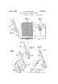
- Fig. 5 is an enlarged front view 0i the pedal portion of lthe lever showing the pri mary and secondary foot engaging portions.
- Fig. 7 is an enlarged elevation of the pedal portion showing a slight modification
- Fig. 8 is a view similar to Fig. 7, showing the primary or anti-friction foot engaging portion displaced and the foot in engagement with the secondary or friction foot engaging portion.
- Fig. 9 is a detail view showing modification of our invention.
- Fig. 10 is a detail of another slight modification'.
- the ,operator may apply the brakes by power with very little more eifort, if any, than is reqpired to depress the foot accelerator, and t e brake pedal may therefore be operated in the same manner as the accelerator pedal, that is to say, the operator may rest his heel the other hand, it is desirable to have the portion of the foot pedal engaged by the foot when great pressure is to be applied, so constructed as to cause a high degree of friction between the foot of the operator and the enl gaged surface of the pedal, so that there v shall be, no danger of the operators foot slipping off of the pedal, especially as the said foot engaging portion assumes a position more nearly horizontal the further it is vdepressed.
- a power actuated brake system for an automotive vehicle which is illustrated diagrammatically inFig, 1. lIn
- this gure 60 representsthe internal combustion engine for propelling the vehicle, prop claimed herein.
- the brake mechanism for the vehicle isillustrated at B, and may be of any desired type and applied to two or more wheels of the vehicle, as may be preferred.
- the brake mechanism is illustrated diagrammatically as comprising a brake drum, 70, a brake band, 71, brake applying lever, 72, and retraeting spring, 73.
- P represents a power actuator, which in this instance is of the type shown and described in our former Patent ⁇ No.
- the actuator comprises a cylinder, 1, in this instance-closed at both ends, and rovided with a piston, 3, having a piston rodl; 5, extending throu h one of the cylinder heads and #connected y a link, 74, with the lever, 72, of the brake mechanism.
- the controlling valve mechanism for the actuator is in this instance located in the hub of the piston, as indicated in Fig. 2, and comprises a valve casing, 11, communicating with the cylinder forward of lthe piston by an aperture, or apertures, 35, and with the cylinder in rear of the piston by an aperture,
- valve casing is provided with oppositely disposed valve seats, 13 and 14, engaged respectively by a suction va1ve, 40,.and Van air inlet valve, 41, the suction valve controlling the communicating aperture, or apertures, 35, and the air inlet valve, 41, controlling the admission of air or other higher pressure fluid through the valve seat, 14.
- valves are conveniently formed of compressed cork, cork composition, 0r rubber, or other suitable material, and are supported upon a longitudinally movable valve actuating sleeve, 20, the interior of which is in this instance open to the atmosphere, the valves engaging the valve sleeve with a sealing lit, and the valve actuating sleeve being provided with collars, 408L and 41, for effecting the opening of one valve after permitting the closing of the other by a movement of the sleeve in either direction, the sleeve being capable of moving through either of said valves.
- the valves, 40 and 41 are pressed yieldingly toward their seats by suitable means, as the spring members, 50.
- valve actuating sleeve is also provided with an aperture, indicated at 24, for admitting the higher pressure fluid, in this instance atmospheric air, to the valve seat, 14.
- valve actuating sleeve extends through-i ⁇ a stufiing box or sealing member in one ⁇ h ead l of the cylinder, and is connected by a' link, ⁇
- valve actuating sleeve is movable with and v also with respect to the piston, and means are provided for limiting the relative movement between said parts.v
- the valve actuating sleeve is shown provided with a collar, 25, within a recess in a cap, 8, secured to the hollow piston rod, 5, and adapted to engage the end of the piston rod when moved in a forwardly direction, as shown in Fig. 2.
- the valve actuating sleeve is also loc held in its rearmost position with respect to f the piston by yielding means.
- a coil spring, 15, interposed between a collar, 16, on the interior of the hollow piston rod, and a collar, 17, on the exterior of the4 valve actuatin sleeve any other suitable means may e employed for this purpose.
- the spring, 15, may serve as the retracting means for the pedal, 88, or a separate spring may-be directly connected to the pedal, as indicated at 9 0, in which case the spring, 15, might be omitted, if desired.
- the actuator herein shown is operated by a differential of fluid pressures obtained by air or other higher fluid pressure operating against vacuum conveniently obtained by a cohnection with the suction passage of the engine between the throttle valve and the engine.
- the operator may, by a further movement of the pedal suiiicient to take fup the lost motion between the valve actuating sleeve and the piston, apply his physical force to the brake mechanism (or other part to be operated) ink addition to the power of the actuator, and in like manner, he may take up 'this lost motion when the engine is not. runnmg or in case of failure of power, or any other reason, and directly apply the brake mechanism by his physical force alone.
- the pedal lever, 88 with a broad foot engaglng pedal portion, indicated at 91, preferably provided with a friction surface, 92, which may be obtained by roughening the surface .or giving yit a cover or coating of some friction material, as rubber or other suitable material, as may be desired.
- This y surface we term the secondary or friction foot engaging surface of the pedal, which has preferably considerable area and a high coefficient of friction.
- the pedal is also provided with a primary foot engaging portion, Awhich hasrarsmaller surface area to engage the foot than the secondary or friction portion, and also has a much lower co-eiicient of friction, so that ⁇ the foot will readily slide over it.
- A hasrarsmaller surface area to engage the foot than the secondary or friction portion
- the primary foot engaging portion as a bar, 94, formed integrally with or connected with a spring plate portion, 95, having bifurcated portions, 96, extending on opposite sides of the pedal lever, 88, and riveted or otherwise secured to the bottom face of the secondary or friction foot engaging portion, as indicated at 97, the spring plate portion having a resistance greater than that of the initial resistance, which is to be overcome in moving the pedal lever to operate valve mechanism, in this instance in excess of the combined resistances 'of the springs, 90 and 15. It follows, there-4 fore, that the operator can rest-his heel on the floor board, indicated at 100 in Fig.
- a slight modification of our invention in which the pedal lever, indicated at 188, is provided with a rigid metallic pedal portion, 1888*, the surface of which is provided with a secondary or friction foot engaging portion, 191, ,having the roughened or friction surface, 192, the part, 191, being conveniently formed tof elastic or yielding material, as molded'rubber, for example, with or withouta reinforcing strip 'of spring sheet material, indicatedy at 191e, and projecting downwardly beyond a lower edge of the rigid pedal portion, 188a, whereit is provided with a transversely disposed bar, 194, having a comparatively smooth rounded anti-friction surface, 193, projecting into a different plane from the corrugated surface, 192, and forming the primary foot engaging surface.
- this device will be the same as that previously described, except that when the operator desires to apply his physical force to the brake mechanism or other part to be opcrated, the additional pressure exerted on the primary foot engaging part, 194, will cause the yielding portion, 191, tobend downwardly, so as to automatically permit the foot of 4.
- a rigid roller yieldingly supported as indicated for example inFig. 10.
- a metal roller, 394 is shown mounted on a pin, 394, carried by a yielding plate 391a secured beneath the pedal tread, 391, and which projects below ⁇ the lower edge of the rigid portion of the pedal, so that after the pedal has been moved downward by the engagement of the foot with the anti-friction r'oller, 394, a further pressure of the foot will depress the roller and automatically bring the operators foot upon the friction surface of the pedal.
- Means for applying brakes of automotive vehicles by power and physical force comprising a pedal lever connected with controlling valve mechanism and with the brakes, and having apedal provided with a primary foot engaging portion, the surface of which has a low co-eflicient of friction for effecting an operation of the valve mechanism, and having a secondary foot engaging portion having a high co-eiiicient of friction, said primary foot enga ing portion being constructed to yield un er pressure and automatically permitthe footyy of the,
- Means for applying brakes of automotive vehicles by power and physical force comprising a pedal lever connected with controlling valve mechanism and with the brakes, and having'a pedal provided with a rigidly supported secondary friction foot engaging portion for enabling the operator to appl his hysicalforce to the brakes, and ⁇ having adjacent to one edge of said secondary foot engaging portiona' primary antifriction foot engaging portion, the foot engaging surface of which is of less area and has a lower co-efiicient of friction than the surface of said secondary foot engaging portion, and constructed to yield under pressure and automatically permit the operators foot to engage said friction foot engaging portion in applying his physical force to the ra es.
- Means for applying'brakes of automotive vehicles by power and physical force comprising a pedal lever connected with controlling valve mechanism and with the brakes, and having a pedal provided with a rigidly supported secondary friction foot engaging portion provided adjacent to its lower edge with a yieldingly supported primary anti-friction yfoot engaging portion constrncted to be displaced by the pressure of the foot thereon, to permit the foot to come into contact with said secondary foot engaging portion.
- Means for applying brakes of automotive vehicles by power and physical force comprising a pedal lever connected with controlling valve mechanism and with the brakes, and having a pedal provided with a secondary friction foot engaging portion having a friction surface, and provided adjacent to its lower edge with a primary antifriction foot engaging portion, the surface of which has a lower co-eilicient of friction, said primary foot engaging portion being yieldingly supported with respect to the pedal, and adapted to be displaced by a pressure of the foot thereon, to permit the foot to engage said secondary foot engaging portion.
- Means for applying brakes of automotive vehicles by power and physical force comprising a pedal lever connected with controlling valve mechanism and with the brakes, retracting means for said pedal lever, said lever provided with a pedal provided witha rigidly supported secondary friction foot ⁇ engaging portion ⁇ having a friction surface, and provided adjacent to the lower edge thereof with a secondary anti-friction foot engaging portion, having a comparatively smooth surface projecting forwardly of said friction surface and supported in operative position by yielding means having greater resistance than the retractingmeans for the pedal, whereby the operator may operate the valve mechanism by engaging the anti-friction portion to effect a power application of the brakes, and may displace said primary ,foot engaging portion to engage said secondaryfoot engaging portion, to apply his physical force to the brakes.
- Means for applying brakes of automotive vehicles by power and physical force comprising a pedal lever connected with controlling valve mechanism and with the brakes, and having a pedal providedwith a rigidly supported secondar friction foot engaging portion having a riction surface, a spring plate member rigidly connected therewith and provided with a primary anti-friction foot engaging portion supported adjacent to the lower edge of the secondary foot engaging portion, and havin a rounded substantially smooth foot .engaging surface, said spring plate member having reater resistance than retracting means or the pedal lever and valve mechanism.
- a pedal lever having a pedal provided with friction foot engaging portion, and an ITS anti-frictiondoot/engaging portion locatedV adjacent to one edge of the friction portion, projecting forwardly thereof and constructed to yield under pressure to permit the oper- 4ators foot to engage said friction portion,
- both of said portions arranged to move the lever when acted on by the foot of the op-I erator.
- a pedal lever having a pedal provided with a friction foot engaging portion, and an vanti-friction foot engaging portion located adjacent to one edge of the rsaid Jfriction portion yieldingly connected with the pedal and projecting forward of said friction portion and adapted to yield under pressure to automatically permit the operators foot to engage the said friction portion of the pedal, both of said portions arranged to move the lever when acted on by the foot of the operator.
Landscapes
- Engineering & Computer Science (AREA)
- Transportation (AREA)
- Mechanical Engineering (AREA)
- Braking Elements And Transmission Devices (AREA)
Description
April 5, 1932. c. s. BRAGG ET AL 1,852,285
BRAKE SYSTEM FOR AUTOMOTIVE VEHICLES Filed Feb. 1e, 192s 2 sheets-sheet 1 April 5, 1932. c. s. BRAGG ET AL BRAKE SYSTEM FOR AUTOMOTIVE VEHICLES Filed Feb. 16, 1928 2 Sheets-Sheet INVENTOR' Patented Apr. 1932 UNITED STATES PATENT OFFICE .ALEB S. BRAGG, OB4 PALM BEACH, FLORIDA, AND VICTOR W.' KLIESRATH, OF PORT WASHINGTON, NEW YORK, ASSIGNORS TO IBRAGG-KLIESRATH CORPORATION, OF LONG ISLAND CITY, NEW YORK, A CORPORATION 0F NEW YORK BRAKE SYSTEM FOR AUTOMOTIVE VEHICLES Application ledl'ebruary 16, 1928. Serial No. 254,648.
@ur invention consists in the novel features hereinafter described, reference being had to the accompanying drawings which show two embodiments of the same selected hy us for purposes of'illustration, and the said invention is fully disclosed in the following description and claims.
Our present invention consists in a novel :foot pedal adapted particularly for use with a poweractuator, for applying the brake mechanisms of an automotive vehicle, the foot pedal being connected with the controlling valve mechanism of the actuator and also with the brake mechanism (or other parts to be operated), so that the physical force of the operator may be applied thereto in addition to that of the actuator, or to 0perate said brake mechanisms in case of failure of power, the said foot pedal being provided with a primary anti-friction foot engaging portlon Aconstructed to engage the Afoot engaging portion, preferably of greater area than the said primary portion, and constructed to provide considerable frlction between its face and the foot of the operator., the said primary or anti-friction foot engaging portion being constructed to yield with respect to the pedal, whenever subjected to more than a predetermined amount of pressure, as for example the amount of pressure required to cilect the operation of the valve mechanism of the actuator, and automatically permit the foot of the operator to engage the secondary or friction foot engaging portion, as for example when it is desired to apply the physical force of the operator directly to the brake mechanism or other parts to be operated, in addition to that Vof the actuator, or to operate the brake mechanism by physical force alone in case o'f failure of power.
In the accompanying drawings which illustrate several embodiments of our invention selected by` us for. purposes of illustration,
Fig. 1 is a diagrammatic view illustrating an installation of brake mechanism l,in an automotive vehicle in connection with a power actuator and a pedal lever embodying our present invention.
Fig. 2 is a detail sectional view of the controlling valve mechanism for the actuator illustrated in Fig. l. w
Fig. 3 is an enlarged detail view showing the pedal lever and a portion of the flooring of the vehicle, and illustrating the normal position of the operatorsfoot for controlling the valve mechanism of the actuator. l
Fig. 4 is a detail view of a portion of the pedal lever showing the primary or antifriction foot engaging portion displaced and the foot of the' operator in engagement with the secondary or friction foot engaging portion.
Fig. 5 is an enlarged front view 0i the pedal portion of lthe lever showing the pri mary and secondary foot engaging portions.
6 is a view of the rear face of the pedal portlon.
Fig. 7 is an enlarged elevation of the pedal portion showing a slight modification, and
illustrating the position of the foot in connection with the primary or anti-friction foot engaging portion.
Fig. 8 is a view similar to Fig. 7, showing the primary or anti-friction foot engaging portion displaced and the foot in engagement with the secondary or friction foot engaging portion.
Fig. 9 is a detail view showing modification of our invention.
Fig. 10 is a detail of another slight modification'. I
another Where a power actuator 1s used to assist the operator Kin applying the brakes, it is customary to employ a power actuator having suicient power to eiect the average stopping of the vehicle without any effort of the operator beyond that necessary to operate the valve mechanism of -the actuator and to overcome, the customary retracting means with which the pedal vor valve mechanism is provided. As this initial resistance may be made as light as desired, the ,operator may apply the brakes by power with very little more eifort, if any, than is reqpired to depress the foot accelerator, and t e brake pedal may therefore be operated in the same manner as the accelerator pedal, that is to say, the operator may rest his heel the other hand, it is desirable to have the portion of the foot pedal engaged by the foot when great pressure is to be applied, so constructed as to cause a high degree of friction between the foot of the operator and the enl gaged surface of the pedal, so that there v shall be, no danger of the operators foot slipping off of the pedal, especially as the said foot engaging portion assumes a position more nearly horizontal the further it is vdepressed. In order that our present. invention may be clearly understood, we have shown it in connection with a power actuated brake system for an automotive vehicle. which is illustrated diagrammatically inFig, 1. lIn
this gure 60 representsthe internal combustion engine for propelling the vehicle, prop claimed herein.
vided with a throttle controlled suction passage from the carburetor, indicated at 65, to the engine cylinders, said passage inclu-ding an intake manifold, 61, a vertical portion, 61", the latter being provided with the usual throttle` valve, indicated at 64. The brake mechanism for the vehicle isillustrated at B, and may be of any desired type and applied to two or more wheels of the vehicle, as may be preferred. In the present instance the brake mechanism is illustrated diagrammatically as comprising a brake drum, 70, a brake band, 71, brake applying lever, 72, and retraeting spring, 73. P represents a power actuator, which in this instance is of the type shown and described in our former Patent `No. 1,583,117 granted May 4, 192,6, and the articular construction of the actuator and its valve mechanism will therefore not be The actuator comprises a cylinder, 1, in this instance-closed at both ends, and rovided with a piston, 3, having a piston rodl; 5, extending throu h one of the cylinder heads and #connected y a link, 74, with the lever, 72, of the brake mechanism. The controlling valve mechanism for the actuator is in this instance located in the hub of the piston, as indicated in Fig. 2, and comprises a valve casing, 11, communicating with the cylinder forward of lthe piston by an aperture, or apertures, 35, and with the cylinder in rear of the piston by an aperture,
or apertures ,'34. The valve casing is provided with oppositely disposed valve seats, 13 and 14, engaged respectively by a suction va1ve, 40,.and Van air inlet valve, 41, the suction valve controlling the communicating aperture, or apertures, 35, and the air inlet valve, 41, controlling the admission of air or other higher pressure fluid through the valve seat, 14. The valves are conveniently formed of compressed cork, cork composition, 0r rubber, or other suitable material, and are supported upon a longitudinally movable valve actuating sleeve, 20, the interior of which is in this instance open to the atmosphere, the valves engaging the valve sleeve with a sealing lit, and the valve actuating sleeve being provided with collars, 408L and 41, for effecting the opening of one valve after permitting the closing of the other by a movement of the sleeve in either direction, the sleeve being capable of moving through either of said valves. The valves, 40 and 41, are pressed yieldingly toward their seats by suitable means, as the spring members, 50. 'Ihe valve actuating sleeve is also provided with an aperture, indicated at 24, for admitting the higher pressure fluid, in this instance atmospheric air, to the valve seat, 14.
The valve actuating sleeve extends through-i` a stufiing box or sealing member in one` h ead l of the cylinder, and is connected by a' link,`
89, with the pedal lever, indicated at 88. The
valve actuating sleeve is movable with and v also with respect to the piston, and means are provided for limiting the relative movement between said parts.v In this instance the valve actuating sleeve is shown provided with a collar, 25, within a recess in a cap, 8, secured to the hollow piston rod, 5, and adapted to engage the end of the piston rod when moved in a forwardly direction, as shown in Fig. 2. The valve actuating sleeve is also loc held in its rearmost position with respect to f the piston by yielding means. In this instance we have shown a coil spring, 15, interposed between a collar, 16, on the interior of the hollow piston rod, anda collar, 17, on the exterior of the4 valve actuatin sleeve, but any other suitable means may e employed for this purpose. The spring, 15, may serve as the retracting means for the pedal, 88, or a separate spring may-be directly connected to the pedal, as indicated at 9 0, in which case the spring, 15, might be omitted, if desired.
The actuator herein shown is operated by a differential of fluid pressures obtained by air or other higher fluid pressure operating against vacuum conveniently obtained by a cohnection with the suction passage of the engine between the throttle valve and the engine.
cylinders. Invthis instance we have shown the forward end ofthe cylinder, 1 connected the suction valve, 40, will be opened, thus con- \1:3
necting the portion of the cylinder forward of the piston with the portion of the cylinder in rear of the piston through the valve chamber, 11, and aperture, or apertures, 34, thus maintaining both portions of the cylinder exhausted when the engine is running, and rmaintaining the piston submerged in vac'- num,
It will be obvious from the foregoing that a very slight pressure on the pedallever sufficient to overcome the initial resistance afforded by the retracting spring, or springs, will be sufficient to shift the valve mechanism so as to open the inlet valve, 41', after closing the suction valve, 40, leaving the piston subjected i to suction on the forward face, and subjected to the pressure of the atmosphere or other source of higher fluid pressure on the rear face, and causing the piston to moveforward and apply the brake mechanism. It will also be seen that when the brake mechanism is fully applied to the extent of the power of the actuator, the operator may, by a further movement of the pedal suiiicient to take fup the lost motion between the valve actuating sleeve and the piston, apply his physical force to the brake mechanism (or other part to be operated) ink addition to the power of the actuator, and in like manner, he may take up 'this lost motion when the engine is not. runnmg or in case of failure of power, or any other reason, and directly apply the brake mechanism by his physical force alone.
As illustrated inFigs. 3, 4, 5 and 6, we provide the pedal lever, 88, with a broad foot engaglng pedal portion, indicated at 91, preferably provided with a friction surface, 92, which may be obtained by roughening the surface .or giving yit a cover or coating of some friction material, as rubber or other suitable material, as may be desired. This y surface we term the secondary or friction foot engaging surface of the pedal, which has preferably considerable area and a high coefficient of friction. The pedal is also provided with a primary foot engaging portion, Awhich hasrarsmaller surface area to engage the foot than the secondary or friction portion, and also has a much lower co-eiicient of friction, so that` the foot will readily slide over it. In Figs. 1, 3, 5 and 6 for example, we have shown the pedal provided with a transversely disposed rounded anti-friction part, indicated at 93, having a comparatively smooth surface, which is conveniently supported yieldingly with respect to the secondary foot engaging' portion. In one embod-i- Viment of our invention-illustrated in Figs.
3, 5 and 6, we have shown the primary foot engaging portion as a bar, 94, formed integrally with or connected with a spring plate portion, 95, having bifurcated portions, 96, extending on opposite sides of the pedal lever, 88, and riveted or otherwise secured to the bottom face of the secondary or friction foot engaging portion, as indicated at 97, the spring plate portion having a resistance greater than that of the initial resistance, which is to be overcome in moving the pedal lever to operate valve mechanism, in this instance in excess of the combined resistances 'of the springs, 90 and 15. It follows, there-4 fore, that the operator can rest-his heel on the floor board, indicated at 100 in Fig. 3, and by engaging the sole of his foot with the primary or anti-friction foot engaging surface, 93, of the pedal, can move the pedal for. ward without flexing the spring plate, portion, 95, and the foot of the operatorwill slide easily over the rounded comparatively smooth anti-friction surface, 93, as the pedal moves forward to operate the valve mechanism and effect an application of the brake mechanism by power. When it becomes necessary to apply the physical force of the operator to the brake mechanism, the operator will naturally apply greater force to the pedal and the spring plate member, 95, will instantly yield, and thus automatically bring the operators foot into engagement with the secondary or friction foot engaging surface, 92, as indicated in Fig. 4, where it will Y be held against slipping, while the operator applies his physical force through the pedal to the brake mechanism.,v
In Figs. 7 and 8, we have shown a slight modification of our invention, in which the pedal lever, indicated at 188, is provided with a rigid metallic pedal portion, 1888*, the surface of which is provided with a secondary or friction foot engaging portion, 191, ,having the roughened or friction surface, 192, the part, 191, being conveniently formed tof elastic or yielding material, as molded'rubber, for example, with or withouta reinforcing strip 'of spring sheet material, indicatedy at 191e, and projecting downwardly beyond a lower edge of the rigid pedal portion, 188a, whereit is provided with a transversely disposed bar, 194, having a comparatively smooth rounded anti-friction surface, 193, projecting into a different plane from the corrugated surface, 192, and forming the primary foot engaging surface. The operation of this device will be the same as that previously described, except that when the operator desires to apply his physical force to the brake mechanism or other part to be opcrated, the additional pressure exerted on the primary foot engaging part, 194, will cause the yielding portion, 191, tobend downwardly, so as to automatically permit the foot of 4.
engaging portion in the form of a transversely "disposed compressible roller, 294, of rubber or other elastic material, mounted lrotatably upon a pin, 2942*, secured to the rigid portion, 291, of the pedal. In this construction the pedal will be operated to effect a power stroke of the actuator by the engagement of the operators foot with the roller, 294, as indicated in full lines in Fig. 9, and when he desires to apply his physical force to the brakes, the
further pressure of his foot will cause the compressible roller, 294, to yield, and alltomatically bring the operators foot into engagement with the friction surface, 291, as indicated in dotted lines in Fig. 9.
ln some instances instead of having a compressible anti-friction roller mounted on a rigid shaft, we may employ a rigid roller yieldingly supported as indicated for example inFig. 10. In this figure a metal roller, 394, is shown mounted on a pin, 394, carried by a yielding plate 391a secured beneath the pedal tread, 391, and which projects below `the lower edge of the rigid portion of the pedal, so that after the pedal has been moved downward by the engagement of the foot with the anti-friction r'oller, 394, a further pressure of the foot will depress the roller and automatically bring the operators foot upon the friction surface of the pedal.
It will be understood that if the pedal were provided only with the friction or roughened surface, and the movement of the pedal was effected by the engagement of the sole of the operators foot whilehis heel rested on the foot board to effec-t a power application of the brake mechanism, the frictional engagement of this roughened surface with the operators foot would be apt to drag the operators foot forward and change the position of his heel with respect to the floor board, and thereby interfere with the accurate control of the valve mechanism.` This is prevented by our invention, ahd as before stated, the valve mechanism of the actuator can be operated by the pedal to effect a power application of the brake mechanism by the engagement of the operators foot with the antifriction surface in very much the same way that the accelerator pedal, or button, is operated, while as soon as greater pressure is exerted by the operator,.the anti-friction surface will yield and automatically bring the operators foot into engagement with the roughened secondary foot engaging portion of the pedal, whenever hev desires to apply his physical force directly to the brake mechanism, thus preventing the slipping of his foot with respect tothe pedal, especially when the pedalhas been moved angularly to aposition more or less nearly parallel with the adjacent portion'fof the floor board, and approaching a horizontal position.
What we claim and desire to secure by Letters Patent is 1. Means for actuating a part of an automotive vehicle, comprising a pedal lever, means for connecting the pedal lever with the part to be operated, and a pedal on said lever having a primary anti-friction foot engaging element constructed to permit' 2. Means` for applying brakes of automotive vehicles by power and by physical force, comprising a pedal lever connected with controlling valve mechanism and with the brakes, and having a pedal provided with a f' primary foot engaging portion for slidingly engaging the sole of the operators foot, while the heel 1s supported to effect the operation of the brakes by power mechanism, and a secondary foot engaging portion of greater area for transmittin the physical force of the operator to the rakes.
3. Means for applymg brakes of automotive vehicles by power and physical force,
comprising a pedal lever connected with controlling Valve mechanism and with the brakes, and having a pedal provided with a primary foot engaging portion adapted to be engaged to effect the operation of said valve mechanism, and a secondary foot engaging portion of greater area, adapted to be engaged to transmit the physical force of the operator to the brakes, said primary foot engaging portion being constructed to yield under pressure and automatically permit the operators foot to engage said second ary foot engaging portion.
4. Means for applying brakes of automotive vehicles by power and physical force, comprising a pedal lever connected with controlling valve mechanism and with the brakes, and having apedal provided with a primary foot engaging portion, the surface of which has a low co-eflicient of friction for effecting an operation of the valve mechanism, and having a secondary foot engaging portion having a high co-eiiicient of friction, said primary foot enga ing portion being constructed to yield un er pressure and automatically permitthe footyy of the,
operator to engage said secondary foot engaging portion vvrhen applying his physical force to the brakes.
5. Means for applying brakes of automotive vehicles by power and physical force, comprising a pedal lever connected with controlling valve mechanism and with the brakes, and having'a pedal provided with a rigidly supported secondary friction foot engaging portion for enabling the operator to appl his hysicalforce to the brakes, and` having adjacent to one edge of said secondary foot engaging portiona' primary antifriction foot engaging portion, the foot engaging surface of which is of less area and has a lower co-efiicient of friction than the surface of said secondary foot engaging portion, and constructed to yield under pressure and automatically permit the operators foot to engage said friction foot engaging portion in applying his physical force to the ra es.
6. Means for applying'brakes of automotive vehicles by power and physical force, comprising a pedal lever connected with controlling valve mechanism and with the brakes, and having a pedal provided with a rigidly supported secondary friction foot engaging portion provided adjacent to its lower edge with a yieldingly supported primary anti-friction yfoot engaging portion constrncted to be displaced by the pressure of the foot thereon, to permit the foot to come into contact with said secondary foot engaging portion.
7., Means for applying brakes of automotive vehicles by power and physical force, comprising a pedal lever connected with controlling valve mechanism and with the brakes, and having a pedal provided with a secondary friction foot engaging portion having a friction surface, and provided adjacent to its lower edge with a primary antifriction foot engaging portion, the surface of which has a lower co-eilicient of friction, said primary foot engaging portion being yieldingly supported with respect to the pedal, and adapted to be displaced by a pressure of the foot thereon, to permit the foot to engage said secondary foot engaging portion.
8. Means for applying\brakes of automotive vehicles by power and physical force, comprising a pedal lever connected with controlling valve mechanism and with the brakesyand having a pedal provided with a secondary friction foot engaging portion rigidly secured thereto, and having adjacent to its lower edge a primary anti-friction foot engaging portion supported in operative position by yielding means having greater resistance than retracting means for the pedal and valve mechanism, whereby said primary anti-friction foot engaging portion may be engaged by the foot of the operator to operate said valve mechanism and effect a power application of the brakes, and will yield to permit the operators foot to be applied to said secondary friction foot engaging portion to apply the physical force of the operator directly tothe brakes.
9. Means for applying brakes of automotive vehicles by power and physical force, comprising a pedal lever connected with controlling valve mechanism and with the brakes, retracting means for said pedal lever, said lever provided with a pedal provided witha rigidly supported secondary friction foot `engaging portion `having a friction surface, and provided adjacent to the lower edge thereof with a secondary anti-friction foot engaging portion, having a comparatively smooth surface projecting forwardly of said friction surface and supported in operative position by yielding means having greater resistance than the retractingmeans for the pedal, whereby the operator may operate the valve mechanism by engaging the anti-friction portion to effect a power application of the brakes, and may displace said primary ,foot engaging portion to engage said secondaryfoot engaging portion, to apply his physical force to the brakes.
10. Means for applying .brakes of automotive vehicles by power vand physical force,
comprising a pedal lever connected with controlling valve mechanism and with the brakes, and having a pedal provided with a rigidly supported secondary frictionfoot engaging portion having a friction surface, and having adjacent to the lower edge thereof a primary anti-friction foot engaging portion inoperative position, and having suliicient power to overcome the initial resistance to the movement of said pedal lever and valve mechanism.
11. Means for applying brakes of automotive vehicles by power and physical force, comprising a pedal lever connected with controlling valve mechanism and with the brakes, and having a pedal providedwith a rigidly supported secondar friction foot engaging portion having a riction surface, a spring plate member rigidly connected therewith and provided with a primary anti-friction foot engaging portion supported adjacent to the lower edge of the secondary foot engaging portion, and havin a rounded substantially smooth foot .engaging surface, said spring plate member having reater resistance than retracting means or the pedal lever and valve mechanism.
12. A pedal lever having a pedal provided with a friction foot engaging portion, and an anti-friction foot engaging portion constructed to yield under pressure, to automatically permit the foot of the operator to engage said friction portion, both of said portions arranged to move the lever when acted on by the foot of the operator.
13. A pedal lever having a pedalprovided with a friction portion and an anti-friction portion projecting forward of the plane of the friction portion and constructed to yield to automatically permit the operators foot to engage the said friction portion, both of said portions arranged' to move the lever when acted on by the foot of the operator.
14. A pedal lever having a pedal provided with friction foot engaging portion, and an ITS anti-frictiondoot/engaging portion locatedV adjacent to one edge of the friction portion, projecting forwardly thereof and constructed to yield under pressure to permit the oper- 4ators foot to engage said friction portion,
both of said portions arranged to move the lever when acted on by the foot of the op-I erator.
15. A pedal lever having a pedal provided with a friction foot engaging portion, and an vanti-friction foot engaging portion located adjacent to one edge of the rsaid Jfriction portion yieldingly connected with the pedal and projecting forward of said friction portion and adapted to yield under pressure to automatically permit the operators foot to engage the said friction portion of the pedal, both of said portions arranged to move the lever when acted on by the foot of the operator. v
In testimony whereof We aix our signatures.
CALEB S. BRAGG. VICTOR W; KLIESRATH.
Priority Applications (1)
| Application Number | Priority Date | Filing Date | Title |
|---|---|---|---|
| US254648A US1852285A (en) | 1928-02-16 | 1928-02-16 | Brake system for automotive vehicles |
Applications Claiming Priority (1)
| Application Number | Priority Date | Filing Date | Title |
|---|---|---|---|
| US254648A US1852285A (en) | 1928-02-16 | 1928-02-16 | Brake system for automotive vehicles |
Publications (1)
| Publication Number | Publication Date |
|---|---|
| US1852285A true US1852285A (en) | 1932-04-05 |
Family
ID=22965060
Family Applications (1)
| Application Number | Title | Priority Date | Filing Date |
|---|---|---|---|
| US254648A Expired - Lifetime US1852285A (en) | 1928-02-16 | 1928-02-16 | Brake system for automotive vehicles |
Country Status (1)
| Country | Link |
|---|---|
| US (1) | US1852285A (en) |
-
1928
- 1928-02-16 US US254648A patent/US1852285A/en not_active Expired - Lifetime
Similar Documents
| Publication | Publication Date | Title |
|---|---|---|
| GB702554A (en) | Improvements in or relating to pneumatic servo-devices for hydraulic master cylinders | |
| US1824032A (en) | Power actuator | |
| US1852285A (en) | Brake system for automotive vehicles | |
| US3011832A (en) | Brake system for vehicles | |
| US2539538A (en) | Safety brake | |
| US2087305A (en) | Brake valve | |
| US2102461A (en) | Brake controlling appliance | |
| US2085550A (en) | Single pedal control for motor vehicles | |
| US2643518A (en) | Vehicle brake control apparatus | |
| US1582118A (en) | Power actuator for the brake mechanism of automotive vehicles | |
| US1801483A (en) | Power actuator | |
| US2117016A (en) | Control mechanism for automotive vehicles | |
| US1826418A (en) | Brake system for automotive vehicles | |
| US1606045A (en) | Brake mechanism | |
| US1940550A (en) | Brake operating mechanism | |
| US1871110A (en) | Automotive brake system | |
| US1845995A (en) | Brake actuating mechanism | |
| US2724469A (en) | Combined brake pedal and throttle control assembly | |
| US1633360A (en) | Throttle-control apparatus for brake-applying mechanism | |
| US1908214A (en) | Braking mechanism | |
| US2028586A (en) | Brake mechanism for automotive vehicles | |
| US1990828A (en) | Control for motor vehicles | |
| US1792750A (en) | Brake mechanism | |
| US4253305A (en) | Assisted braking device | |
| US1928566A (en) | Power braking and clutch releasing mechanism for automotive vehicles |