US1852277A - Framing tool - Google Patents
Framing tool Download PDFInfo
- Publication number
- US1852277A US1852277A US345297A US34529729A US1852277A US 1852277 A US1852277 A US 1852277A US 345297 A US345297 A US 345297A US 34529729 A US34529729 A US 34529729A US 1852277 A US1852277 A US 1852277A
- Authority
- US
- United States
- Prior art keywords
- segment
- graduations
- stick
- rafters
- adjustable
- Prior art date
- Legal status (The legal status is an assumption and is not a legal conclusion. Google has not performed a legal analysis and makes no representation as to the accuracy of the status listed.)
- Expired - Lifetime
Links
- 238000009432 framing Methods 0.000 title description 5
- 239000011295 pitch Substances 0.000 description 6
- 241001591024 Samea Species 0.000 description 1
- 238000010276 construction Methods 0.000 description 1
- 238000005259 measurement Methods 0.000 description 1
- 230000000717 retained effect Effects 0.000 description 1
- 210000003813 thumb Anatomy 0.000 description 1
Images
Classifications
-
- E—FIXED CONSTRUCTIONS
- E04—BUILDING
- E04G—SCAFFOLDING; FORMS; SHUTTERING; BUILDING IMPLEMENTS OR AIDS, OR THEIR USE; HANDLING BUILDING MATERIALS ON THE SITE; REPAIRING, BREAKING-UP OR OTHER WORK ON EXISTING BUILDINGS
- E04G21/00—Preparing, conveying, or working-up building materials or building elements in situ; Other devices or measures for constructional work
- E04G21/14—Conveying or assembling building elements
- E04G21/16—Tools or apparatus
- E04G21/18—Adjusting tools; Templates
- E04G21/1891—Cut-marking templates for rafters; Templates used for assembling building frameworks
Definitions
- One object of the invention is to provide a measuring device of the character described whereby timbers may be measured, to be Cut, at the desired angle, for use in buildings.
- il, more particular' object of the invention is to provide a scale, or measuring device
- rafters may be out on the desired bevel, and the angle of the bevel may be readily varied for roofs of different pitches.
- Figure l shows an end view of the device.
- Figure 6 shows a plan view of a roof framework, shown for the purpose of better illustrating the use of the scale.
- the numeral 1 designates a flat measuring stick having a slot 2 extending approxik mately from one end to the other thereof.
- a flange 5 which lies adjacent the stick 1 and has the outstanding stud bolts G, 3 which project through slot 2 and whose outer ends are threaded to receive the clamp nuts 7, 7 by means of which said segment 3 is adjustably secured to the measuring stick 1929.
- the said face of said segment 3 has the scales 14, 15 for the common cuts and the hip and valleycuts and the front face of the stick 1 has the scales 16 and 17 for the common cuts and hip and valley cuts, as hereinafter defined.
- the flange 5 has a pointer 18 yattached thereto whose free end is upturned into association with the scales 16, 17.
- the pointer 18 After deciding the pitch to be given to the roof the pointer 18 should be moved to the number on the scale 16 designating the degree of rise or pitch of the roof previously decided upon and the edge of the arm 8 and CFI Cal
- the edge D of the rule 25 should then be brought to the same figure of the scales 14, 21 respectively as designated, or shown in Figure 1, the thumb screws 7 12, and 31, should then be tightened with the bolt 11 at the outer end of slot 10.
- the implement should then be applied to the rafter or timber to be cut as shown in Figure 1. Lines should then be drawn along the edges indicated by the letters c, c to delineate the plate notch to be cut in the common rafter to receive the plate 36. Also amark should be made on the rafter or timber at the pointindicated by the letter B and the scale should then be lifted from the timber and the point A placed at the 'point mark B.
- This operation marks off one measure the length of which vcorresponds to the length of rafter for one foot of the width of the building, and measures of equal length to the number of one half of the width of the building in feet are then measured off on the rafter and a diagonal mark should be then made across the rafter along the edge D and the rafter cut olf along said line.
- the plate notch previously delineated along the edges c, c should then be cut out and the pattern as thus provided, should be used to cut out all of the common rafters.
- the ends of the rafters beyond said notches, should be cut olf so as to leave the desired extension for the eaves, in completing this pattern.
- the straight edge E of the rule 26 should be brought or set at. the same figure used for the common cuts and then measured oft on the rafter as hereinbefore explained, using the point A as a starting point and marking along the edges c, c and D and also along the edge E and the cut for the beveled end of the rafter should be made along the lines drawn at the edges D, E.
- each set of these short, or jack, rafters should be madey two measures shorter than the previous ones and this will space the rafters, when erected into the roof structure, two feet between centers measured on the wall plate, this for the reason that each length of the measuring stick, taken at the desired pitch, equals one linear foot across the building.
- the valley rafters are cut just the same as the short or jack rafters for the hip roof with the exception that no plate notch is necessary and a straight line should be drawn from the point AA along the adjacent edge of the arm 9 entirely across the rafter and the timber should'be cut ofi along said line. ⁇ liiorder to measure off the main hip rafters 37' and valley rafters 38, the device must be reset or re adjusted, and this is accomplished by moving the pointer 18 to the desired figure of the scale 17; that is, to the sameA figure ⁇ previously employed for the common cuts of the scale 16, and securing said pointer at said figure.
- each scale represent the rise,or pitch, in inches for each foot run of the building, that is, for each linear foot of the building taken on a horizontal line delined by vertical parallel lines through the ends of the rafter in question.
- a measuring device including a measuring stick, a graduated' segment carried thereby f and adjustable thereon, a square pivotally mounted upon said segment and one arm of which is associated With the graduations thereof, a pair of graduated segments spaced equidistant from the adjustable segment and fixed to said measuring stick, a rule having a. straight edge pivotally mounted upon, and associated With the graduations of, each fixed segment.
- a device of the character described including a measuring stick, a graduated segment carried by said stick and adjustable thereon, a square mounted upon said segment and one arm of which is associated with the graduations thereof, a graduated segment fixed upon said measuring stick and spaced from said adjustable segment, a rule pivotally mounted on the fixed segment and associated With the graduations of said fixed segment, and means connecting the square adjustably and pivotally to the segment Whereon it is mounted.
Landscapes
- Engineering & Computer Science (AREA)
- Architecture (AREA)
- Mechanical Engineering (AREA)
- Civil Engineering (AREA)
- Structural Engineering (AREA)
- Length-Measuring Instruments Using Mechanical Means (AREA)
- A Measuring Device Byusing Mechanical Method (AREA)
Description
Apri15,1932. Afm/HEEL@ n 1,852,277
FRAMING TOOL Filed March 8, 1929 2 Sheets-Sheet l HIP2VALLEY cursA 4 COMMON Guns I Z8 O I l1!) l April 5, 1932 A. L. WHEELER FRAMING TOOL Filed March 8. 1929 2 sheets-sheet 2 Patented Apr. 5, 1932 UNITED STATES ATENT OFFICE ARTHUR L. WHEELER, OF CLEVELAND, TEXAS, ASSIGNOR OF ONE-HALF TO S. E. BUDG-ERS, OF LIBERTY COUNTY, TEXAS FRAMING TOOL Application led. March 8,
This invention relates to new and useful improvements in a framing tool.
One object of the invention is to provide a measuring device of the character described whereby timbers may be measured, to be Cut, at the desired angle, for use in buildings.
il, more particular' object of the invention is to provide a scale, or measuring device,
whereby rafters may be out on the desired bevel, and the angle of the bevel may be readily varied for roofs of different pitches.
Another object of the invention is to provide a device of the character described whereby common rafters, and hip and valley 16 rafters may be readily measured to be out at any bevel desired to give the roof the desired pitch.
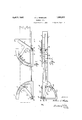
Viith the above and other objects in view this invention has particular relation to certain novel features of construction, operation and arrangement of parts an example of which is given in this specification and illustrated in the accompanying drawings, wherein Figure 1 shows a side elevation of the device.
Figure 2 shows a side view taken at right angles to the View shown in Figure 1.
Figure 3 shows a cross sectional view taken on the line 3-3 of Figure 1.
Figure l shows an end view of the device.
Figure 5 shows a side view of a rafter cut from measurements of the scale, and
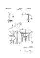
Figure 6 shows a plan view of a roof framework, shown for the purpose of better illustrating the use of the scale.
Referring now more particularly to the drawings, wherein like numerals of reference designate similar parts in each of the figures, the numeral 1 designates a flat measuring stick having a slot 2 extending approxik mately from one end to the other thereof. rThere is an arcuate segment 3 fixed to one end of the base 4f and overturned from this base there is a flange 5 which lies adjacent the stick 1 and has the outstanding stud bolts G, 3 which project through slot 2 and whose outer ends are threaded to receive the clamp nuts 7, 7 by means of which said segment 3 is adjustably secured to the measuring stick 1929. Serial N'o. 345,297.
1. lThere is a squarehaving the arms 8, 9 at right angles to each other and the latter of which has the aligned extension 9 formed with an oblong longitudinal slot 10 to recel ve the stud bolt 11 which projects out from one end of the base l and is eXteriorly threaded to receive the clamp nut 12 by means of which the square, above referred to, is adjustably secured to the base li. The free end of the arm 8 overlies the front face of the segment 3 and has a lip 13 which engages under the segment 3 and thereby retains the arm 8 in association with said segment. The said face of said segment 3 has the scales 14, 15 for the common cuts and the hip and valleycuts and the front face of the stick 1 has the scales 16 and 17 for the common cuts and hip and valley cuts, as hereinafter defined. The flange 5 has a pointer 18 yattached thereto whose free end is upturned into association with the scales 16, 17.
Secured to one end of the measuring stick I there are the arcuate segments 19,20 disposed at right angles to each other the front face of the former of which has the scales 21, 22 for common cuts and hip and valley cuts, and
the front face of the latter of which has the scales 23, 24 for bevel cuts, all as hereinafter defined. Pivoted to the outer ends of the bases of these segments 19, 2O are the rules or straight edges 25, 26' whose free ends are retained in association with .the scales of their respective segments by the lips 27, 28 respectively, which engage under the respective segments. The pivotal connections between the rules 25, 26, and their respective segments are obtained by means of the respective stud bolts 29, 3() which project from said bases through bearing in said rules and whose outer ends are threaded to receive the clamp nuts 31, e2.
In Figure 6 the common rafters are designated by the numeral 33, the hip rafters are designated by the numeral 34 and the valley rafters by the numeral 35.
After deciding the pitch to be given to the roof the pointer 18 should be moved to the number on the scale 16 designating the degree of rise or pitch of the roof previously decided upon and the edge of the arm 8 and CFI Cal
the edge D of the rule 25 should then be brought to the same figure of the scales 14, 21 respectively as designated, or shown in Figure 1, the thumb screws 7 12, and 31, should then be tightened with the bolt 11 at the outer end of slot 10. The implement should then be applied to the rafter or timber to be cut as shown in Figure 1. Lines should then be drawn along the edges indicated by the letters c, c to delineate the plate notch to be cut in the common rafter to receive the plate 36. Also amark should be made on the rafter or timber at the pointindicated by the letter B and the scale should then be lifted from the timber and the point A placed at the 'point mark B. This operation marks off one measure the length of which vcorresponds to the length of rafter for one foot of the width of the building, and measures of equal length to the number of one half of the width of the building in feet are then measured off on the rafter and a diagonal mark should be then made across the rafter along the edge D and the rafter cut olf along said line. The plate notch previously delineated along the edges c, c should then be cut out and the pattern as thus provided, should be used to cut out all of the common rafters. The ends of the rafters beyond said notches, should be cut olf so as to leave the desired extension for the eaves, in completing this pattern.
In order to form a hip roof rafter the straight edge E of the rule 26 should be brought or set at. the same figure used for the common cuts and then measured oft on the rafter as hereinbefore explained, using the point A as a starting point and marking along the edges c, c and D and also along the edge E and the cut for the beveled end of the rafter should be made along the lines drawn at the edges D, E. However each set of these short, or jack, rafters, should be madey two measures shorter than the previous ones and this will space the rafters, when erected into the roof structure, two feet between centers measured on the wall plate, this for the reason that each length of the measuring stick, taken at the desired pitch, equals one linear foot across the building.
The valley rafters are cut just the same as the short or jack rafters for the hip roof with the exception that no plate notch is necessary and a straight line should be drawn from the point AA along the adjacent edge of the arm 9 entirely across the rafter and the timber should'be cut ofi along said line. `liiorder to measure off the main hip rafters 37' and valley rafters 38, the device must be reset or re adjusted, and this is accomplished by moving the pointer 18 to the desired figure of the scale 17; that is, to the sameA figure `previously employed for the common cuts of the scale 16, and securing said pointer at said figure. rEhe straight edge 0 of theV arm 8 and the straight edge CZ of the rule 25 should now be brought to the corresponding figure of the scales 15 and 22 for the hip and valley cuts and there secured. Before making this adjustment, however, of the arm 8, the arm 9 should be moved longitudinally on the stud bolt 11, the long slot 10 permitting this, so as to properly form the plate notch defined by the edges c, c. in other words after the coinmon rafters have been cut and while 'the arm 9 is positioned as shown in Figure 1 the adjustifient is then made for cutting the hip and valley rafters as above explained. When the arm 9, however, is swung around on the pin 11 the angle between the edges 0, o will describe an arc and will be carried out closer to the adjacent margin of the iafter so that the arm 9 must be adjusted back or downwardly as illustrated in Figure 1 so as to give theproper depth to the notch defined by .the edges c, c. This notch must be the same as the corresponding notch of the common rafters and the device is set to properly form this notch when it is adjusted back in the slot 10 so as to give the depth of the common rafter notch. The valley rafters should then be measured olf exactly as the common cuts were measured as hereinbefore explained, the number of measures necessary to give the required length, beingV one half of the width of the building in feet. Y
The designating numerals of each scale represent the rise,or pitch, in inches for each foot run of the building, that is, for each linear foot of the building taken on a horizontal line delined by vertical parallel lines through the ends of the rafter in question.
What I claim is:
1. A device of the character described including a measuring stick, an arcuatesegment mounted on said stick and adjustable lengthwise thereon and having graduations, a square pivotally and adjustably mounted upon said segment and having one armassociated with said graduations, an arcuate ysegment fixed to said stick and spaced from said adjustable segment, and having graduations, a rule pivotally mounted on the iiXed segment and having. a straight edge associated with the graduations of said iXed segment.
2. A'device of the character describedincluding a measuring stick, an arcuate segment mounted on said stick and adjustable lengthwise thereon and having graduations, a square pivotally and adjustably mounted upon said segment and having one arm associated with said graduations, van arcuate segment fixed to said stick and spaced from said adjustable segment, and having graduations, a rule pivotally mounted on the iixed segment and having a straight edge associated with the graduations of said fixed seglment, another segment, having' graduations, -and fixed to said stick and spaced from said adjustable segment, a rule having a straight edge pivoted to said last named segment and having its free end associated with the graduations thereof.
3. A device of the character described including a measuring stick, tivo segments .fixed thereto and disposed in planes at substantially right angles, each segment having graduations thereon, rules pivotally mounted on said segments and having straight edges, one rule being associated with the graduations of each segment, a segment adj ustably mounted on said measuring stick and having graduations, a square pivotally and adjustably mounted upon said adjustable segment and having one arm associated with the graduations on said adjustable segment.
al. A device of the character described including a measuring stick, two segments fixed thereto and disposed in planes at substantially' right angles, each segment having graduations thereon, rules pivotally mounted on said segments and having straight edges, one rule being associated With the graduations of each segment, a segment adjustably mounted on said measuring stick and having graduations, a square pivotally and adjustably mounted on said adjustable segment and having one arm associated With the graduations on said adjustable segment, said measur- .ing stick having graduations, and a pointer carried by said adjustable segment and associated With the graduations of said measuring stick.
5. A device of the character described including a measuring stick, a graduated segment carried by said stick and adjustable thereon, a square pivotally mounted upon said segment and one arm of which is associat-ed with the graduations of said segment, a graduated segment fixed on said measuring stick and spaced from said adjustable segment, a rule pivotally mounted on, and asso ciated With the graduations of', said xed segment, said measuring stick being also provided With graduations, and a pointer fixed upon said adjustable segment and associated with the graduations on said measuring stick.
6. A measuring device including a measuring stick, a graduated' segment carried thereby f and adjustable thereon, a square pivotally mounted upon said segment and one arm of which is associated With the graduations thereof, a pair of graduated segments spaced equidistant from the adjustable segment and fixed to said measuring stick, a rule having a. straight edge pivotally mounted upon, and associated With the graduations of, each fixed segment.
7. A measuring device including a measuring stick, a graduated segment carried by said stick and adjustable thereon, a square pivotally mounted upon and one arm of which is associated With, said graduated segment, a pair of graduated segments spaced equidistant from the adjustable segment and fixed to said measuring stick, a rule pivotally mounted on each fixed segment and having a straight edge associated with its corresponding fixed segment, said measuring stick having graduations and said adjustable segment having a pointer associated with the graduations of said measuring stick.
8. A device of the character described including a measuring stick, a graduated segment carried by said stick and adjustable thereon, a square mounted upon said segment and one arm of which is associated with the graduations thereof, a graduated segment fixed upon said measuring stick and spaced from said adjustable segment, a rule pivotally mounted on the fixed segment and associated With the graduations of said fixed segment, and means connecting the square adjustably and pivotally to the segment Whereon it is mounted.
In testimony whereof I have signed my name to this specification.
ARTHUR L. WHEELER.
Priority Applications (1)
| Application Number | Priority Date | Filing Date | Title |
|---|---|---|---|
| US345297A US1852277A (en) | 1929-03-08 | 1929-03-08 | Framing tool |
Applications Claiming Priority (1)
| Application Number | Priority Date | Filing Date | Title |
|---|---|---|---|
| US345297A US1852277A (en) | 1929-03-08 | 1929-03-08 | Framing tool |
Publications (1)
| Publication Number | Publication Date |
|---|---|
| US1852277A true US1852277A (en) | 1932-04-05 |
Family
ID=23354438
Family Applications (1)
| Application Number | Title | Priority Date | Filing Date |
|---|---|---|---|
| US345297A Expired - Lifetime US1852277A (en) | 1929-03-08 | 1929-03-08 | Framing tool |
Country Status (1)
| Country | Link |
|---|---|
| US (1) | US1852277A (en) |
Cited By (6)
| Publication number | Priority date | Publication date | Assignee | Title |
|---|---|---|---|---|
| US2460151A (en) * | 1944-06-09 | 1949-01-25 | Socony Vacuum Oil Co Inc | Apparatus for gas-solid contact operations |
| US2475706A (en) * | 1948-02-10 | 1949-07-12 | Douglas J Jamieson | Orthodontic instrument for measuring the frankfort-mandibular plane angle |
| US2575697A (en) * | 1950-02-24 | 1951-11-20 | Marvin W Willis | Combination measuring instrument for layout work |
| US2908080A (en) * | 1954-04-08 | 1959-10-13 | Robert L Varbel | Adjustable rafter square |
| US3183596A (en) * | 1964-04-23 | 1965-05-18 | Earnest B Shaw | Template |
| WO2017005941A1 (en) * | 2015-07-06 | 2017-01-12 | Monlleó Lloret José | Measuring device for dentistry and method for the use thereof |
-
1929
- 1929-03-08 US US345297A patent/US1852277A/en not_active Expired - Lifetime
Cited By (6)
| Publication number | Priority date | Publication date | Assignee | Title |
|---|---|---|---|---|
| US2460151A (en) * | 1944-06-09 | 1949-01-25 | Socony Vacuum Oil Co Inc | Apparatus for gas-solid contact operations |
| US2475706A (en) * | 1948-02-10 | 1949-07-12 | Douglas J Jamieson | Orthodontic instrument for measuring the frankfort-mandibular plane angle |
| US2575697A (en) * | 1950-02-24 | 1951-11-20 | Marvin W Willis | Combination measuring instrument for layout work |
| US2908080A (en) * | 1954-04-08 | 1959-10-13 | Robert L Varbel | Adjustable rafter square |
| US3183596A (en) * | 1964-04-23 | 1965-05-18 | Earnest B Shaw | Template |
| WO2017005941A1 (en) * | 2015-07-06 | 2017-01-12 | Monlleó Lloret José | Measuring device for dentistry and method for the use thereof |
Similar Documents
| Publication | Publication Date | Title |
|---|---|---|
| US4527337A (en) | Framing stud template | |
| US3289305A (en) | Rafter measuring tape | |
| US1852277A (en) | Framing tool | |
| US2023539A (en) | Roof pitch indicator | |
| US1559386A (en) | Gauge | |
| US2251208A (en) | Combination square | |
| US1821103A (en) | Roof framing tool | |
| US2056948A (en) | Carpenter's tool | |
| US2575077A (en) | Automatic tape measure | |
| US2654954A (en) | Roof framer | |
| US639125A (en) | Square. | |
| US2908080A (en) | Adjustable rafter square | |
| US2090835A (en) | Carpenter's tool | |
| US2726452A (en) | Carpenters calculating and lay-out tool | |
| US1346050A (en) | Gage for bevels, miters, and the like | |
| US2575697A (en) | Combination measuring instrument for layout work | |
| US2180509A (en) | Combined square, level, protractor, etc. | |
| US496714A (en) | Measuring and drawing tool | |
| US1980765A (en) | Roof framing tool | |
| US1825759A (en) | Bevel square | |
| US1477002A (en) | Roof-framing square | |
| US2368958A (en) | Framing instrument | |
| US1618862A (en) | Combination square | |
| US2198948A (en) | Rafter and brace square | |
| US1704462A (en) | Square |