US1852260A - Combination marine lamp and mooring bit - Google Patents
Combination marine lamp and mooring bit Download PDFInfo
- Publication number
- US1852260A US1852260A US334679A US33467929A US1852260A US 1852260 A US1852260 A US 1852260A US 334679 A US334679 A US 334679A US 33467929 A US33467929 A US 33467929A US 1852260 A US1852260 A US 1852260A
- Authority
- US
- United States
- Prior art keywords
- lamp
- plug
- light
- mooring
- bit
- Prior art date
- Legal status (The legal status is an assumption and is not a legal conclusion. Google has not performed a legal analysis and makes no representation as to the accuracy of the status listed.)
- Expired - Lifetime
Links
- 210000005069 ears Anatomy 0.000 description 4
- 238000005286 illumination Methods 0.000 description 4
- 238000010276 construction Methods 0.000 description 3
- 230000004048 modification Effects 0.000 description 3
- 238000012986 modification Methods 0.000 description 3
- 239000004020 conductor Substances 0.000 description 2
- 238000004519 manufacturing process Methods 0.000 description 1
- 239000000463 material Substances 0.000 description 1
Images
Classifications
-
- B—PERFORMING OPERATIONS; TRANSPORTING
- B63—SHIPS OR OTHER WATERBORNE VESSELS; RELATED EQUIPMENT
- B63B—SHIPS OR OTHER WATERBORNE VESSELS; EQUIPMENT FOR SHIPPING
- B63B45/00—Arrangements or adaptations of signalling or lighting devices
-
- B—PERFORMING OPERATIONS; TRANSPORTING
- B63—SHIPS OR OTHER WATERBORNE VESSELS; RELATED EQUIPMENT
- B63B—SHIPS OR OTHER WATERBORNE VESSELS; EQUIPMENT FOR SHIPPING
- B63B21/00—Tying-up; Shifting, towing, or pushing equipment; Anchoring
- B63B21/04—Fastening or guiding equipment for chains, ropes, hawsers, or the like
- B63B21/045—T-shaped cleats
-
- B—PERFORMING OPERATIONS; TRANSPORTING
- B63—SHIPS OR OTHER WATERBORNE VESSELS; RELATED EQUIPMENT
- B63B—SHIPS OR OTHER WATERBORNE VESSELS; EQUIPMENT FOR SHIPPING
- B63B45/00—Arrangements or adaptations of signalling or lighting devices
- B63B45/06—Arrangements or adaptations of signalling or lighting devices the devices being intended to illuminate vessels' decks or interior
-
- B—PERFORMING OPERATIONS; TRANSPORTING
- B63—SHIPS OR OTHER WATERBORNE VESSELS; RELATED EQUIPMENT
- B63B—SHIPS OR OTHER WATERBORNE VESSELS; EQUIPMENT FOR SHIPPING
- B63B2201/00—Signalling devices
- B63B2201/04—Illuminating
- B63B2201/08—Electric light
Definitions
- This invention pertains to marine lights. More particularly it pertains to an improved combination light and bit. It is an object of the invention to provide a light of simple and rugged construction. It is also an object to provide a light which may be employed as a mooring bit. An important object is to provide a light, or signal lamp of simple construction in which the source of illumination is readily accessible in a novel manner. Further objects and the advantages of the in ventive idea will be brought out in the following specification.
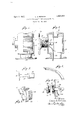
- Fig. 1 is a side elevation of a light, or signal lamp, constructed according to my invention
- Fig. 2 is a side elevation, in section, showing the interior and also showing, partly removed from the body of the light, a lamp carrying plug member;
- Fig. 3 is a bracket for carrying the source of illumination.
- Fig. 4 is a retaining strip for holding the lenses in place.
- Fig. 5 is a detail of a modification of a part of the light.
- Fig. 6 is a detailed view of part of a modified form of my invention.
- the light housing 6, is cast as a single, integral member, including the base 7, by means of which it may be secured to the boat, preferabl by means of screws passing thru holes in t 1e said base.
- the interior of the light housing forms a light chamber preferably having light reflecting surfaces associated in such position as to proJect light rays thru the openings 8, to which suitable lenses 9, are fitted, and held in place by the retaining strips 10, and 11.
- the drawings show a lamp having two lenses, the same be ing separated by the bar 12, which it will be understood will be left out if only one lens having an aperture of approximately 180 is to be employed.
- a necked portion 13 Between the body of the light housing 6, and the base 7, is a necked portion 13, which is designed to serve as a mooring rope guide or rope retainin means.
- a suitable socket 1 for a flag pole or staff.
- the rear of the housing is an opening 15, preferably, as shown a tapped hole, adapted to receive a plug 16, having a threaded portion 17
- a plug 16 having a threaded portion 17
- an electric incandescent lamp is employed as the source of illumination, and is indicated at 18, the same being held in the socket 19, which in turn is carried by the bracket 20.
- This bracket 20, better shown in Fig. 3, is provided with a circular base 21, having a hole 22, at its center.
- the said bracket is so carried by the plug 16, as to permit the rotation of the plug, when it is being screwed into or out of the lamp, without rotating the lamp bracket, thus avoiding fouling of the electric conducting wires 24.
- the plug 16 is providedwith ears, or projections 25, which besides aiding in removing the plug from the lamp body also act as a cleat, thus affording a place to which a rope may be secured, in a well known manner. Accordingly I provide a combined lamp, bit, and mooring cleat in a single, rugged and practical unit. a The tapped hole 15, is carried by a boss 26 in the drawings. It will be understood that if it is desired to provide a flush exterior for the lamp body, the thread carrying portion 26, may be extended into the interior, instead of having same project as illustrated. For convenience in finishing the lamp exterior this modification may be preferred in some cases.
- the boss or extension 26 acts as a support for which the base 38, of the electric light socket member 37, rests, the said socket member extending into the lamp body thru theopening 36.
- a projecting member 39, on the base 38 may be employed as an aid in removing the electric lamp, which is accom lished by withdrawing the lamp socket mem er 37 from the opening 36, the electric conducting cable 40, being long enough to permit access to the lamp socket for changing the bulb, etc. It will be seen that when the plug member 32, is screwed into place, the threaded portion 33, acts to retain the electric lamp in position thru the medium of the base 38, against which it is adapted to impinge.
- the boss 41 may be eliminated also in this modification as described in connection with Fig. 2, by projecting same inwardly, thereby leaving a flush exterior for convenience in finishing the outside surface of the lamp body.
- a plug member 45 having a threaded portion 46.
- Ears 47 are provided to facilitate screwing the plug into the lamp body or for removing same. I may however eliminate the ears 47, by knurling the head of the plug 45.
- a combination marine lamp and mooring bit comprising a hollow body having a glazed opening, a base, a rope guide between the base and the glazed opening, a removable illuminating means, and a rope securing cleat formed as a part of the removable illuminating means.
- a combination marine lamp and bit comprising a hollow light housing having a zed p ning th ein, a base member, mooring rope guide between the glazed opening and the base, and a mooring cleat formed on' the back' of the removable illuminating m n r 4.
- a marine lamp comprising a hollow casing a glazed opening in said casing; a threaded opening in said casing, 'said threaded opening of sufficient sizeto permit the illuminate ing means to be inserted therethrough; a threaded closure plug for closing said thread opening, and a mooring cleat on said plug, and said threaded plug adapted to support the illuminating means.
- a marine lamp comprising a hollow easing, a glazed openin in said casing, an opening in said casing of suflicient size to permit illuminating means to be inserted therethrough, a closure plug for closing said opening, a light socket, a bracket for supporting said light socket, electrical conductors etend-. ing into said casing for supplying electrieal current to the illuminating means, and means for securing said bracket to said plug so to prevent twisting of the ele'ctricalconduetors when the closure plug is being removed and secured in place.
- a combination marine lamp and moor "ing bit comprising a hollow body having a glazed opening formed therein, illuminating means removably secured in said hollow body,
Landscapes
- Chemical & Material Sciences (AREA)
- Engineering & Computer Science (AREA)
- Combustion & Propulsion (AREA)
- Mechanical Engineering (AREA)
- Ocean & Marine Engineering (AREA)
- Non-Portable Lighting Devices Or Systems Thereof (AREA)
Description
AALPTIEE F, 1932. 1 5 PERKiNS 1,852,260
COMBINATION MARINE LAMP AND MOORING BIT Filed Jan. 24, 1929 A I NVENTOR L 0a w 5 Per/@725.
ATTORNEY Patented Apr. 5, 1932 LOUIS EDWARD PERKINS, OF BROOKLYN, NEW YORK COMBINATION MARINE LAMP AND MOORING BIT Application filed January 24, 1929. Serial no. 334,679.
This invention pertains to marine lights. More particularly it pertains to an improved combination light and bit. It is an object of the invention to provide a light of simple and rugged construction. It is also an object to provide a light which may be employed as a mooring bit. An important object is to provide a light, or signal lamp of simple construction in which the source of illumination is readily accessible in a novel manner. Further objects and the advantages of the in ventive idea will be brought out in the following specification.
Referring to the accompanying drawings:
Fig. 1 is a side elevation of a light, or signal lamp, constructed according to my invention;
Fig. 2 is a side elevation, in section, showing the interior and also showing, partly removed from the body of the light, a lamp carrying plug member;
Fig. 3 is a bracket for carrying the source of illumination.
Fig. 4 is a retaining strip for holding the lenses in place.
Fig. 5 is a detail of a modification of a part of the light.
Fig. 6 is a detailed view of part of a modified form of my invention.
Preferably, the light housing 6, is cast as a single, integral member, including the base 7, by means of which it may be secured to the boat, preferabl by means of screws passing thru holes in t 1e said base. The interior of the light housing forms a light chamber preferably having light reflecting surfaces associated in such position as to proJect light rays thru the openings 8, to which suitable lenses 9, are fitted, and held in place by the retaining strips 10, and 11. The drawings show a lamp having two lenses, the same be ing separated by the bar 12, which it will be understood will be left out if only one lens having an aperture of approximately 180 is to be employed. Between the body of the light housing 6, and the base 7, is a necked portion 13, which is designed to serve as a mooring rope guide or rope retainin means.
In the upper part of the housing 1s a suitable socket 1 1, for a flag pole or staff. At
the rear of the housing is an opening 15, preferably, as shown a tapped hole, adapted to receive a plug 16, having a threaded portion 17 It will be seen that when this plug is in place, as shown in Fig. 1, and the lamp secured in place on the boat, or wherever it is used, the said plug 16, affords convenient access to the interior of the lamp. This fact is taken advantage of in the present invention, in a novel manner. Preferably an electric incandescent lamp is employed as the source of illumination, and is indicated at 18, the same being held in the socket 19, which in turn is carried by the bracket 20. This bracket 20, better shown in Fig. 3, is provided with a circular base 21, having a hole 22, at its center. By means of a screw 23, the said bracket is so carried by the plug 16, as to permit the rotation of the plug, when it is being screwed into or out of the lamp, without rotating the lamp bracket, thus avoiding fouling of the electric conducting wires 24. By this means it is a simple matter to remove and replace an electric light bulb, whereas heretofore it has been necessary, either to remove the lamp from the boat or providea special door, both involving labor and eX- pensc. The electric conductor 24,-should be sufiiciently long to permit removing the electric bulb clear of the lamp body for convenience in handling. It will be noted that the plug 16, is providedwith ears, or projections 25, which besides aiding in removing the plug from the lamp body also act as a cleat, thus affording a place to which a rope may be secured, in a well known manner. Accordingly I provide a combined lamp, bit, and mooring cleat in a single, rugged and practical unit. a The tapped hole 15, is carried by a boss 26 in the drawings. It will be understood that if it is desired to provide a flush exterior for the lamp body, the thread carrying portion 26, may be extended into the interior, instead of having same project as illustrated. For convenience in finishing the lamp exterior this modification may be preferred in some cases. Where the electric bulb retaining plug is provided with ears so as to also serve as a rope receiving cleat, the boss or extension 26, acts as a support for which the base 38, of the electric light socket member 37, rests, the said socket member extending into the lamp body thru theopening 36. A projecting member 39, on the base 38, may be employed as an aid in removing the electric lamp, which is accom lished by withdrawing the lamp socket mem er 37 from the opening 36, the electric conducting cable 40, being long enough to permit access to the lamp socket for changing the bulb, etc. It will be seen that when the plug member 32, is screwed into place, the threaded portion 33, acts to retain the electric lamp in position thru the medium of the base 38, against which it is adapted to impinge. The boss 41, may be eliminated also in this modification as described in connection with Fig. 2, by projecting same inwardly, thereby leaving a flush exterior for convenience in finishing the outside surface of the lamp body. In Fig. 5, is illustrated a plug member 45, having a threaded portion 46. Ears 47, are provided to facilitate screwing the plug into the lamp body or for removing same. I may however eliminate the ears 47, by knurling the head of the plug 45.
It will be seen that I'provide a simpleand practical combination lamp unit which is in- 2. A combination marine lamp and mooring bit comprising a hollow body having a glazed opening, a base, a rope guide between the base and the glazed opening, a removable illuminating means, and a rope securing cleat formed as a part of the removable illuminating means.
3. A combination marine lamp and bit comprising a hollow light housing having a zed p ning th ein, a base member, mooring rope guide between the glazed opening and the base, and a mooring cleat formed on' the back' of the removable illuminating m n r 4. A marine lamp comprising a hollow casing a glazed opening in said casing; a threaded opening in said casing, 'said threaded opening of sufficient sizeto permit the illuminate ing means to be inserted therethrough; a threaded closure plug for closing said thread opening, and a mooring cleat on said plug, and said threaded plug adapted to support the illuminating means. i
5. A marine lamp comprising a hollow easing, a glazed openin in said casing, an opening in said casing of suflicient size to permit illuminating means to be inserted therethrough, a closure plug for closing said opening, a light socket, a bracket for supporting said light socket, electrical conductors etend-. ing into said casing for supplying electrieal current to the illuminating means, and means for securing said bracket to said plug so to prevent twisting of the ele'ctricalconduetors when the closure plug is being removed and secured in place.
' LOUIS EDWARD ERKINS- eXpensive to manufacture,'and which, among a other improvements, embodies unique means for removably carrying the source of illumination. I have illustrated my improvements in conjunction with a conventional type of marine lamp, but it will .be understood the design of the lamp may be widely varied without departing from the scope of the inventive idea herein disclosed. It will be seen that I provide a combination lamp, bit, andvcleat and that the mooring or other rope, when in use, does not interfere or mask the light projecting face or faces of the lamp. Preferably I cast the lamp body and base as a hollow single member, but it will be understood that I reserve the right to employ any suitable construction, design and material, in practicing my invention;
I claim:
j 1. A combination marine lamp and moor "ing bit comprising a hollow body having a glazed opening formed therein, illuminating means removably secured in said hollow body,
an opening in said hollow body through which the illuminating'means is accessible, and removable closing means for sa d opening, said closing means providing a mooring cleat.
Priority Applications (1)
| Application Number | Priority Date | Filing Date | Title |
|---|---|---|---|
| US334679A US1852260A (en) | 1929-01-24 | 1929-01-24 | Combination marine lamp and mooring bit |
Applications Claiming Priority (1)
| Application Number | Priority Date | Filing Date | Title |
|---|---|---|---|
| US334679A US1852260A (en) | 1929-01-24 | 1929-01-24 | Combination marine lamp and mooring bit |
Publications (1)
| Publication Number | Publication Date |
|---|---|
| US1852260A true US1852260A (en) | 1932-04-05 |
Family
ID=23308301
Family Applications (1)
| Application Number | Title | Priority Date | Filing Date |
|---|---|---|---|
| US334679A Expired - Lifetime US1852260A (en) | 1929-01-24 | 1929-01-24 | Combination marine lamp and mooring bit |
Country Status (1)
| Country | Link |
|---|---|
| US (1) | US1852260A (en) |
Cited By (4)
| Publication number | Priority date | Publication date | Assignee | Title |
|---|---|---|---|---|
| US5216972A (en) * | 1991-09-06 | 1993-06-08 | Dufrene John K | Lighted cleat |
| US6539886B2 (en) * | 2001-06-15 | 2003-04-01 | Mastercraft Boat Company, Inc. | Integrated light and tow-line-attachment assembly for a boat |
| US20040228134A1 (en) * | 2003-05-12 | 2004-11-18 | Leboeuf Michael J. | Combination port cover and boat lighting apparatus |
| US6968796B1 (en) * | 2003-11-18 | 2005-11-29 | David W. Burke | Mooring cleat with illumination |
-
1929
- 1929-01-24 US US334679A patent/US1852260A/en not_active Expired - Lifetime
Cited By (5)
| Publication number | Priority date | Publication date | Assignee | Title |
|---|---|---|---|---|
| US5216972A (en) * | 1991-09-06 | 1993-06-08 | Dufrene John K | Lighted cleat |
| US6539886B2 (en) * | 2001-06-15 | 2003-04-01 | Mastercraft Boat Company, Inc. | Integrated light and tow-line-attachment assembly for a boat |
| US20040228134A1 (en) * | 2003-05-12 | 2004-11-18 | Leboeuf Michael J. | Combination port cover and boat lighting apparatus |
| US6883944B2 (en) | 2003-05-12 | 2005-04-26 | Leboeuf Michael J. | Combination port cover and boat lighting apparatus |
| US6968796B1 (en) * | 2003-11-18 | 2005-11-29 | David W. Burke | Mooring cleat with illumination |
Similar Documents
| Publication | Publication Date | Title |
|---|---|---|
| US1873310A (en) | Collapsible reflector | |
| US2798148A (en) | Twinkling electric illuminated ornament | |
| US2352804A (en) | Fluorescent lighting fixture | |
| US1852260A (en) | Combination marine lamp and mooring bit | |
| US2229962A (en) | Lamp base and socket | |
| US2298042A (en) | Flashlight | |
| US1903087A (en) | Lighting construction | |
| US4026416A (en) | Light bulb storage bank | |
| US1500482A (en) | Illuminated target | |
| US2230853A (en) | Light signal | |
| US1027306A (en) | Automobile-lamp. | |
| US1934947A (en) | Marine lamp | |
| US1526691A (en) | Electric-light fixture | |
| US1630745A (en) | Suspending device for lighting fixtures | |
| US1697803A (en) | Automobile signal lamp | |
| US1617793A (en) | Flash light | |
| US1950369A (en) | Flash light baton | |
| US3238366A (en) | Lighting fixture including concealed swivel assembly | |
| US1589320A (en) | Theater-seat light | |
| US1522942A (en) | Incandescent-electric-lamp fixture | |
| US1105770A (en) | Miniature electric lamp. | |
| JP2563713Y2 (en) | Emergency lighting equipment | |
| US1794687A (en) | Electric-light fixture | |
| US2050438A (en) | Electric guide lamp | |
| US1205196A (en) | Lighting-fixture. |