US1852229A - Oiling system - Google Patents
Oiling system Download PDFInfo
- Publication number
- US1852229A US1852229A US465039A US46503921A US1852229A US 1852229 A US1852229 A US 1852229A US 465039 A US465039 A US 465039A US 46503921 A US46503921 A US 46503921A US 1852229 A US1852229 A US 1852229A
- Authority
- US
- United States
- Prior art keywords
- oil
- pressure
- outlets
- bearings
- rate
- Prior art date
- Legal status (The legal status is an assumption and is not a legal conclusion. Google has not performed a legal analysis and makes no representation as to the accuracy of the status listed.)
- Expired - Lifetime
Links
- 229940060184 oil ingredients Drugs 0.000 description 32
- 239000003921 oil Substances 0.000 description 31
- 239000010724 circulating oil Substances 0.000 description 8
- 238000011010 flushing procedure Methods 0.000 description 6
- 230000001105 regulatory effect Effects 0.000 description 3
- 239000011521 glass Substances 0.000 description 2
- 238000012856 packing Methods 0.000 description 2
- 230000010349 pulsation Effects 0.000 description 2
- 230000002159 abnormal effect Effects 0.000 description 1
- 239000000295 fuel oil Substances 0.000 description 1
- 239000012535 impurity Substances 0.000 description 1
- 239000013049 sediment Substances 0.000 description 1
- 239000002699 waste material Substances 0.000 description 1
Images
Classifications
-
- F—MECHANICAL ENGINEERING; LIGHTING; HEATING; WEAPONS; BLASTING
- F16—ENGINEERING ELEMENTS AND UNITS; GENERAL MEASURES FOR PRODUCING AND MAINTAINING EFFECTIVE FUNCTIONING OF MACHINES OR INSTALLATIONS; THERMAL INSULATION IN GENERAL
- F16N—LUBRICATING
- F16N7/00—Arrangements for supplying oil or unspecified lubricant from a stationary reservoir or the equivalent in or on the machine or member to be lubricated
- F16N7/38—Arrangements for supplying oil or unspecified lubricant from a stationary reservoir or the equivalent in or on the machine or member to be lubricated with a separate pump; Central lubrication systems
- F16N7/385—Central lubrication systems
Definitions
- This invention relates to oiling systems for machines having a plurality of bearings intended to be lubricated continuously, the system being preferably though not necessarilyself-contained with or -driven bythe machine to be lubricated, varying in speed therewith and starting and stopping therewith, so as-to be automatic in its cooperative relation with the machine to be lubricated.
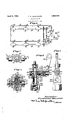
- Fig. l is an elevation of an oiling system exemplifying my invention
- Fig. 2 is a plan of one of the feed nozzles on an enlarged scale;
- Fig. 3 is a sectional view on line 3-3 of Fig. 2;
- Fig. 4 is a sectional vieN of the pressure regulating valve
- Fig. 5 is an elevation of the regulating valve as viewed from the right-hand side of Fig. 4f.
- an oiling system having a reservoir 6 equipped with suitable provision for the introduction of oil, as a filling cap 8.
- the reservoir is preferably providedwith a strainer '10 to strain the oil introduced thereinto, and a suitable level indicator, herein a gage glass l2.
- the reservoir supplies a conduit 14 having a ⁇ plurality of outlets, herein exemplied by feed nozzles each designated generally by the numeral 16, which deliver oil to corresponding bearings conventionally represented at -l8, in which one or more shafts may be journaled.
- il is circulated by a suitable pump designated generally by the numeral 22, which may be of any desired type, the one 1921.
- rlhe pump furnishes a pulsating pressure, and its speed is proportional to that of the machine and starts and stops therewith.
- the pump is located below the reservoir, and is therefore always primed.
- the pump draws oil from a@ the reservoir at a point below the level of the '.oil therein, and is provided with any usual inlet and outlet check valves 34 and 36, which cause the oil to travel through the conduit and nozzles in series in the direction 55 indicated by the arrows.
- the oil minus the amount supplied to the bearings, returns to the reservoir, passing iirst Vthrough a pressure regulator 38, thence through the screen, and thence to the pump, where it is again circulated throu h the system.
- the nozzle is herein provided with a casing conveniently comprising two parts, 40 and 42, the latter encircling the former and provided with an annular passage 44, through which the oil passes on its way from an inlet 46 to an outlet 48.
- This annular passage communicates through one or more, herein a plurality of, openings 50; with a chamber or cylinder 52 having a piston 54 working thereln.
- Said piston carries a suitable valve, herein a needle valve 56, cooperating withla seatv 58 to cont-rol the 85 ⁇ flow of oil from the cylinder to an outlet assage 60 leading to the bearing to be lu riy cated.
- the valve is raised and lowered b the pulsations of pressure in the system ue to the reciprocation of the. lump plunger.
- a suitable stop 62 which is preferably manually adjustable, to the end that v 10' the normal rate of discharge from the nozzle may be regulated at will.
- the stop is the lower end of a stem 62, whose height is conveniently varied by providing the same with a screw-threaded portion 64 threaded into a nut 66 having nonrotative connection with the valve casing as by splines 68. Sincethe nut cannot rotate and is normall held against axial movement, rotation of tlie stem is accompanied Lby lengthwise movement of the latter.
- Opening movement of the needle valve is yieldingly resisted by a suitable spring 70, herein helically coiled about the stem and seated at one end against a shoulder 72 formed on the stem, and at its other end against the lower end of a chamber 74 in which the spring is received.
- a suitable spring 70 herein helically coiled about the stem and seated at one end against a shoulder 72 formed on the stem, and at its other end against the lower end of a chamber 74 in which the spring is received.
- the piston Above the shoulder 72, the piston is provided with an inwardly projecting flange 76, which overlies the shoulder,
- the stem is provided externally. of the valvecasing with a suitable handle, herein a knob 78, by means of which the stem may be rotated to makethe desired adjustment of the rate of feed.
- a packing 79 may be provided about the stem to prevent leakage and to maintain the adjustment of the stem by frictional engagement therewith.
- An appropriate indicator may be provided to indicate the ap roximate or relative amount of oil bein ed, such indicator in the present examp e comprising a pointer 80 carried by the knob 78 and cooperating with a suitably graduated dial 82. 'Suitable provision is made for temporarily superseding the normal rate of feed by an increased rate. This may be accomplished either manually at each individual nozzle, or collectively at all of the nozzles.
- the nut 66 is 'mounted to slide axially, and its upward movement is normally resisted by a spring 84, whose strength is relatively greater than that of the spring 70.
- a spring 84 whose strength is relatively greater than that of the spring 70.
- the pressure regulator will now be described, reference being had to Figs. 4 and 5.
- the regulator in the present example comprises a casing 86 having an inlet 88 and an outlet 90, said casing presenting a cylinder 92 in Which is mounted a piston 94 which controls the passage of oil from the inlet to the outlet.
- This piston can never entirely close the passage, but a restricted openingis left by providing the piston with .
- a reduced end 96 which normally abuts against a fixed stop 98 conveniently in the form of a plug threaded into the casing.
- a spring 100 normally seats the piston against the stop, but yields when the pressure tends to rise above a predetermined point, thereby increasing the size of the restricted opening and allowing a greater amount of oil to flow past the end of the piston, thus maintaining a certain or constant range of pulsating pressure in the system,-i. e. from atmospheric pressure to a maximum as determined by the adjusted load ⁇ on the spring 100.
- This pressure may be temporarily increased for the purpose of flushing all of the bearings simultaneously by manually increasing the resistance presented by the spring, or holding the piston against its seat.
- Outward movement of the piston may be limited by any ⁇ suitable means, as a fixed'stop ⁇ 112 conveniently formed on a rib 114, which extends between the arms 104; If desired,means may be provided to indicate the normal and flushing-positions of the lever, and in the present example, the latter is to this end provided with a pointer 116, while the rib 114 is inscribed with the Words Flush and Normal suitably placed to correspond with the normal and flushing positions Of the lever. It should be understood,
- atubular plunger 108 internally f threaded to vreceive a correspondingly threadf may be observed through one or more, herein a plurality "of windows 120 presented by the casing and surrounding a glass tube 122 having its ends seated against packing Washers 124 and 126, and held in place by a hollow "screw 128 threaded into the casing.
- the low of oil observed through the windows serves asr anindication that the system is functiongThe general operation. of the system should be evident without further description.
- the system has many advantages as compared with other oiling systems. Oil is supplied to a plurality of bearings independently of each other, but in a.
- each bearing beingV lieptsupplied with oil under any given pressure and at any adjusted rate.
- This rate may be increased for any desired period in all of the bearings, or if desired any particular bearing may be given a temporarily increased supply of oil independently of the others. in any event, the' adjusted rates of feed are automatically restored when the tem orary increase ceases.
- the use of force fee is desirable, because the reservoir may be placed at any convenient point for filling, and the regulator at some convenient lpoint for adjustment and observation of the pressure and feed. For a given setting of feed adjustment, the normal rate of feed remains substantially constant, despite variatlon in the viscosity of oil consequent upon temperature changes.
- Another advantage of the .force feed system is that sufficient pressure 1s.
- an oiling system the combination of la reservoir for a supply of oil, a conduit leading from said reservoir past a series of bearings where it has outlets and from the last outlet back to said reservoir, a p ump for cir culating oil through said conduit and reservoir, and means presenting a constantlyl open valve interposed ⁇ in said conduit between the last outlet of the series and thereservoir, and means presenting a yielding resistance to the further o ening of said valve under the iniuence o the pressure in ysaid conduit.
- a circulatory oil system having a series of outlets for supslying bearings,'means for circulating oil un er pressure past said outlets, means at each outlet normally maintain' ⁇ ing an established rate of discharge, and other means at each outlet for temporarily superseding suchV rate by an increased rate at such outlet.
- a circulatory oil system having a series of outlets for supplying bearings, means for er pressure past said outcirculating oil un lets, yielding means ⁇ at each outlet normally maintaining an established rate of discharge,
- a circulatory oil system having a series of outlets for supplying bearings, means for circulating oil under pressure past said outlets, yielding means at each outlet responsive to the oil pressure, for normally maintaining an established rate of discharge proportioned to such pressure, and means for causing a temporary increase of the oil pressure without change of speed of said circulating means, thereby to cause a temporarily increased rate of discharge at all of said outlets.
- A'circulatory oil system having a series of outlets for supplying bearings, means for normally circulating oil under pressure past said outlets, and means for causing the temporary Bushing of any particular bearing and the automatic restoration of the normal feeding rate following the flushing of such bearf ing.
- a circulatory oil system having a series of outlets for supplying bearings, means for normally circulating oil under pressure past said outlets, and means for causing the temporary flushing of all of said bearings simultaneously and the automatic restoration of the normal feeding rate following the iiushing of said bearings.
- a circulatory oil system having a series of outlets for supplying bearings, means for normally circulating oil under pressure past said outlets, means for causing the temporary flushing of any particular bearing followed by the automatic restoration of the normal flow to such bearing, and means for causing the temporary iiushing of all of said bearings 'simultaneously followed by the automatic fue taininga normalrate of discharge of oil at each outlet, and manually operable means for causing such normal rate to be temporarily superseded by an increased rate followed by the automatic resumption of said normal rate.
- a circulating oil system having a series of outlets for supplying bearings, means for l normally circulating oil under pressure past said outlets, ⁇ means for automatically maintaining a normal pressure of the oil ilowing past said outlets, and manually operable means for causing such normalpressure to be temporarily su rseded by an increased pressure followed y the automatic resumption lof said normal pressure.
Landscapes
- Engineering & Computer Science (AREA)
- General Engineering & Computer Science (AREA)
- Mechanical Engineering (AREA)
- Reciprocating Pumps (AREA)
Description
F. C. BLANCHARD April 5, 1932.
OILING SYSTEM Filed April 27 ,A
Ina/emv: v Fiedeaz'ct 0I laiaawi,
Patented Apr.I 5, 1932 PATENT OFFICE FREDERICK C. BLANCHARD, F DETROIT, MICHIGAN OILING SYSTEM:`
` "Application led April 27,
This invention relates to oiling systems for machines having a plurality of bearings intended to be lubricated continuously, the system being preferably though not necessarilyself-contained with or -driven bythe machine to be lubricated, varying in speed therewith and starting and stopping therewith, so as-to be automatic in its cooperative relation with the machine to be lubricated.
\ The invention will be best understood by reference to the following description, when taken in connection with the accompanying drawings. of one illustrative embodiment thereof, while its scope will be more particu:y larly pointed out in the appended claims.
ln the drawings:
Fig. l is an elevation of an oiling system exemplifying my invention Fig. 2 is a plan of one of the feed nozzles on an enlarged scale;
Fig. 3 is a sectional view on line 3-3 of Fig. 2;
Fig. 4 is a sectional vieN of the pressure regulating valve; and
Fig. 5 is an elevation of the regulating valve as viewed from the right-hand side of Fig. 4f.
Referring to the drawings, and to the embodiment of the invention which' is selected for exemplication, there is shown an oiling system having a reservoir 6 equipped with suitable provision for the introduction of oil, as a filling cap 8. The reservoir is preferably providedwith a strainer '10 to strain the oil introduced thereinto, and a suitable level indicator, herein a gage glass l2. The reservoir. supplies a conduit 14 having a` plurality of outlets, herein exemplied by feed nozzles each designated generally by the numeral 16, which deliver oil to corresponding bearings conventionally represented at -l8, in which one or more shafts may be journaled. il is circulated by a suitable pump designated generally by the numeral 22, which may be of any desired type, the one 1921. Serial No. 465,039.
herein shown being of the reciprocating t e, and having a casing 24 presenting a cylin er 26, in which a plunger or piston 28 is mounted to reciprocate, and is operated by any appropriate means, herein an eccentric rod 30 50 and an eccentric 32, the latter being driven by any suitable source of power, preferably that of the machine to belubricated, the eccentric to that end being herein secured to one of the shafts 20. rlhe pump furnishes a pulsating pressure, and its speed is proportional to that of the machine and starts and stops therewith. Preferably the pump is located below the reservoir, and is therefore always primed. The pump draws oil from a@ the reservoir at a point below the level of the '.oil therein, and is provided with any usual inlet and outlet check valves 34 and 36, which cause the oil to travel through the conduit and nozzles in series in the direction 55 indicated by the arrows. The oil, minus the amount supplied to the bearings, returns to the reservoir, passing iirst Vthrough a pressure regulator 38, thence through the screen, and thence to the pump, where it is again circulated throu h the system.
rThe preferre form of feed nozzlewill now be described, reference being had "to Figs. 2 and 3. The nozzle is herein provided with a casing conveniently comprising two parts, 40 and 42, the latter encircling the former and provided with an annular passage 44, through which the oil passes on its way from an inlet 46 to an outlet 48. This annular passage communicates through one or more, herein a plurality of, openings 50; with a chamber or cylinder 52 having a piston 54 working thereln. Said piston carries a suitable valve, herein a needle valve 56, cooperating withla seatv 58 to cont-rol the 85` flow of oil from the cylinder to an outlet assage 60 leading to the bearing to be lu riy cated. i
The valve is raised and lowered b the pulsations of pressure in the system ue to the reciprocation of the. lump plunger. This termined by a suitable stop 62, which is preferably manually adjustable, to the end that v 10' the normal rate of discharge from the nozzle may be regulated at will. In the present example, the stop is the lower end of a stem 62, whose height is conveniently varied by providing the same with a screw-threaded portion 64 threaded into a nut 66 having nonrotative connection with the valve casing as by splines 68. Sincethe nut cannot rotate and is normall held against axial movement, rotation of tlie stem is accompanied Lby lengthwise movement of the latter. Opening movement of the needle valve is yieldingly resisted by a suitable spring 70, herein helically coiled about the stem and seated at one end against a shoulder 72 formed on the stem, and at its other end against the lower end of a chamber 74 in which the spring is received. Above the shoulder 72, the piston is provided with an inwardly projecting flange 76, which overlies the shoulder,
whereby, when the stem is lifted and the shoulder brings up against the flange, the piston is lifted by the stem.
The stem is provided externally. of the valvecasing with a suitable handle, herein a knob 78, by means of which the stem may be rotated to makethe desired adjustment of the rate of feed. A packing 79 may be provided about the stem to prevent leakage and to maintain the adjustment of the stem by frictional engagement therewith. An appropriate indicator may be provided to indicate the ap roximate or relative amount of oil bein ed, such indicator in the present examp e comprising a pointer 80 carried by the knob 78 and cooperating with a suitably graduated dial 82. 'Suitable provision is made for temporarily superseding the normal rate of feed by an increased rate. This may be accomplished either manually at each individual nozzle, or collectively at all of the nozzles. To this end, the nut 66 is 'mounted to slide axially, and its upward movement is normally resisted by a spring 84, whose strength is relatively greater than that of the spring 70. When, therefore, in the vnormal operation of the device, the valve is lifted by the pulsations of pressure, the lower end of the stem serves to limit the valve to a certain predetermined opening. 1When, however, an abnormal pressure is developed in the system by the use of a pressure regulator presently to be described, the nut 66 is lifted in opposition to the spring 84, and thus permits an increased valve opening. This, ofv course, affects all for flushing the bearing, as soon as the nut is allowed to seat under the influence of the` spring 84, there will be an automatic resumption of the normal rate of discharge.
The pressure regulator will now be described, reference being had to Figs. 4 and 5. The regulator in the present example, comprises a casing 86 having an inlet 88 and an outlet 90, said casing presenting a cylinder 92 in Which is mounted a piston 94 which controls the passage of oil from the inlet to the outlet. This piston can never entirely close the passage, but a restricted openingis left by providing the piston with .a reduced end 96, which normally abuts against a fixed stop 98 conveniently in the form of a plug threaded into the casing. A spring 100 normally seats the piston against the stop, but yields when the pressure tends to rise above a predetermined point, thereby increasing the size of the restricted opening and allowing a greater amount of oil to flow past the end of the piston, thus maintaining a certain or constant range of pulsating pressure in the system,-i. e. from atmospheric pressure to a maximum as determined by the adjusted load `on the spring 100. This pressure may be temporarily increased for the purpose of flushing all of the bearings simultaneously by manually increasing the resistance presented by the spring, or holding the piston against its seat. In the present example, this is conveniently -accomplished by the use of a lever 102 bifurcated to present a pair of arms 104, which rest against shoulders 106'v preed plug 110, which presents an abutment for the outer end of the spring. When, therefore, the upper end of the lever is swung toward the right in Fig. 4, the plunger is moved inward, thereby compressing the spring to a greater extent, or if desired, holding the piston against its seat. Outward movement of the piston may be limited by any` suitable means, as a fixed'stop `112 conveniently formed on a rib 114, which extends between the arms 104; If desired,means may be provided to indicate the normal and flushing-positions of the lever, and in the present example, the latter is to this end provided with a pointer 116, while the rib 114 is inscribed with the Words Flush and Normal suitably placed to correspond with the normal and flushing positions Of the lever. It should be understood,
of the valves in the system, and by this sented by atubular plunger 108 internally f threaded to vreceive a correspondingly threadf may be observed through one or more, herein a plurality "of windows 120 presented by the casing and surrounding a glass tube 122 having its ends seated against packing Washers 124 and 126, and held in place by a hollow "screw 128 threaded into the casing. The low of oil observed through the windows serves asr anindication that the system is functiongThe general operation. of the system should be evident without further description. The system has many advantages as compared with other oiling systems. Oil is supplied to a plurality of bearings independently of each other, but in a. cooperative manner, each bearing beingV lieptsupplied with oil under any given pressure and at any adjusted rate. This rate may be increased for any desired period in all of the bearings, or if desired any particular bearing may be given a temporarily increased supply of oil independently of the others. in any event, the' adjusted rates of feed are automatically restored when the tem orary increase ceases. IThe use of force fee is desirable, because the reservoir may be placed at any convenient point for filling, and the regulator at some convenient lpoint for adjustment and observation of the pressure and feed. For a given setting of feed adjustment, the normal rate of feed remains substantially constant, despite variatlon in the viscosity of oil consequent upon temperature changes. Another advantage of the .force feed system is that sufficient pressure 1s. developed to clear the pipe lines of obstructmns such as dirt, waste, sediment, and heavy oil ingredients or impurities. By the use of'a machine having a self-contained system 1n which the pump is driven bythe machine and varies in speed therewith, and starts and stops therewith, no attention is ordinarily required on the part of the operator. Moreover, all of the outlets are closed immediately the machine and its pump stop. However, if
a. machine is cold, all of the bearings may be flushed with oil whenv starting, or any individual bearing showing ydistress may be flushed until relieved.
Having thus described one embodiment of the invention, but Without limiting myself thereto, what l claim and desire by Letters Patent to secure is:
1. ln an oiling system, the combination of la reservoir for a supply of oil, a conduit leading from said reservoir past a series of bearings where it has outlets and from the last outlet back to said reservoir, a p ump for cir culating oil through said conduit and reservoir, and means presenting a constantlyl open valve interposed` in said conduit between the last outlet of the series and thereservoir, and means presenting a yielding resistance to the further o ening of said valve under the iniuence o the pressure in ysaid conduit.
2. A circulatory oil system having a series of outlets for supslying bearings,'means for circulating oil un er pressure past said outlets, means at each outlet normally maintain'` ing an established rate of discharge, and other means at each outlet for temporarily superseding suchV rate by an increased rate at such outlet.
3. A circulatory oil system having a series of outlets for supplying bearings, means for er pressure past said outcirculating oil un lets, yielding means` at each outlet normally maintaining an established rate of discharge,
and means for temporarily increasing the oil'.
pressure opposed to said yielding means, therebysuperseding such rate' by an increased rate at all of said outlets conjointly.
4. A circulatory oil system having a series of outlets for supplying bearings, means for circulating oil under pressure past said outlets, yielding means at each outlet responsive to the oil pressure, for normally maintaining an established rate of discharge proportioned to such pressure, and means for causing a temporary increase of the oil pressure without change of speed of said circulating means, thereby to cause a temporarily increased rate of discharge at all of said outlets.
5. A'circulatory oil system having a series of outlets for supplying bearings, means for normally circulating oil under pressure past said outlets, and means for causing the temporary Bushing of any particular bearing and the automatic restoration of the normal feeding rate following the flushing of such bearf ing. Y
6. A circulatory oil system having a series of outlets for supplying bearings, means for normally circulating oil under pressure past said outlets, and means for causing the temporary flushing of all of said bearings simultaneously and the automatic restoration of the normal feeding rate following the iiushing of said bearings.
7 A circulatory oil system having a series of outlets for supplying bearings, means for normally circulating oil under pressure past said outlets, means for causing the temporary flushing of any particular bearing followed by the automatic restoration of the normal flow to such bearing, and means for causing the temporary iiushing of all of said bearings 'simultaneously followed by the automatic fue taininga normalrate of discharge of oil at each outlet, and manually operable means for causing such normal rate to be temporarily superseded by an increased rate followed by the automatic resumption of said normal rate.
9. A circulating oil system having a series of outlets for supplying bearings, means for l normally circulating oil under pressure past said outlets, `means for automatically maintaining a normal pressure of the oil ilowing past said outlets, and manually operable means for causing such normalpressure to be temporarily su rseded by an increased pressure followed y the automatic resumption lof said normal pressure.
In testimony whereof, I have signed my name to this specification. i
FREDERICK C. BLANCHARD.
:,ssaaaa y
Priority Applications (1)
| Application Number | Priority Date | Filing Date | Title |
|---|---|---|---|
| US465039A US1852229A (en) | 1921-04-27 | 1921-04-27 | Oiling system |
Applications Claiming Priority (1)
| Application Number | Priority Date | Filing Date | Title |
|---|---|---|---|
| US465039A US1852229A (en) | 1921-04-27 | 1921-04-27 | Oiling system |
Publications (1)
| Publication Number | Publication Date |
|---|---|
| US1852229A true US1852229A (en) | 1932-04-05 |
Family
ID=23846265
Family Applications (1)
| Application Number | Title | Priority Date | Filing Date |
|---|---|---|---|
| US465039A Expired - Lifetime US1852229A (en) | 1921-04-27 | 1921-04-27 | Oiling system |
Country Status (1)
| Country | Link |
|---|---|
| US (1) | US1852229A (en) |
Cited By (3)
| Publication number | Priority date | Publication date | Assignee | Title |
|---|---|---|---|---|
| US2428915A (en) * | 1943-09-03 | 1947-10-14 | Wright Aeronautical Corp | Engine slushing system |
| US2554002A (en) * | 1947-07-30 | 1951-05-22 | Herman S Beamesderfer | Check valve |
| US5198723A (en) * | 1988-05-10 | 1993-03-30 | Parker William P | Luminous panel display device |
-
1921
- 1921-04-27 US US465039A patent/US1852229A/en not_active Expired - Lifetime
Cited By (3)
| Publication number | Priority date | Publication date | Assignee | Title |
|---|---|---|---|---|
| US2428915A (en) * | 1943-09-03 | 1947-10-14 | Wright Aeronautical Corp | Engine slushing system |
| US2554002A (en) * | 1947-07-30 | 1951-05-22 | Herman S Beamesderfer | Check valve |
| US5198723A (en) * | 1988-05-10 | 1993-03-30 | Parker William P | Luminous panel display device |
Similar Documents
| Publication | Publication Date | Title |
|---|---|---|
| US1852229A (en) | Oiling system | |
| US3139156A (en) | Sight feed lubricator | |
| US2174797A (en) | Pressure regulator | |
| US2145245A (en) | Central lubrication | |
| US3044484A (en) | By-pass valves | |
| US2025479A (en) | Fuel feeding system for oil burners | |
| US1943605A (en) | Greasing apparatus | |
| US2316000A (en) | Automatic crankcase oil filler | |
| US2407923A (en) | Pump | |
| US1712791A (en) | Relief valve | |
| US3516517A (en) | Air lubrication system | |
| US2205559A (en) | Lubricator | |
| US402640A (en) | Sight-feed lubricator | |
| US1968000A (en) | Lubricating system | |
| US2000913A (en) | Lubrication of machinery | |
| US2138755A (en) | Liquid dispensing apparatus | |
| US2609891A (en) | Lubricating apparatus | |
| US2478521A (en) | Engine lubricant conditioning system | |
| US2054772A (en) | Check valve | |
| US986512A (en) | Automatic start and stop feed for oil-pumps. | |
| US2195209A (en) | Lubrication system | |
| US2387941A (en) | Pumping system | |
| US1958396A (en) | Liquid feed system | |
| DE1600344C2 (en) | Lubricating device for the shaft bearings of a gas turbine engine | |
| US2112860A (en) | Lubricating system |