US1852150A - Apparatus and process for treating hydrocarbons - Google Patents
Apparatus and process for treating hydrocarbons Download PDFInfo
- Publication number
- US1852150A US1852150A US186465A US18646527A US1852150A US 1852150 A US1852150 A US 1852150A US 186465 A US186465 A US 186465A US 18646527 A US18646527 A US 18646527A US 1852150 A US1852150 A US 1852150A
- Authority
- US
- United States
- Prior art keywords
- chamber
- main
- tubes
- hydrocarbons
- main chamber
- Prior art date
- Legal status (The legal status is an assumption and is not a legal conclusion. Google has not performed a legal analysis and makes no representation as to the accuracy of the status listed.)
- Expired - Lifetime
Links
- 229930195733 hydrocarbon Natural products 0.000 title description 21
- 150000002430 hydrocarbons Chemical class 0.000 title description 21
- 238000000034 method Methods 0.000 title description 6
- 230000008016 vaporization Effects 0.000 description 16
- 239000007788 liquid Substances 0.000 description 10
- 238000005336 cracking Methods 0.000 description 8
- 239000004215 Carbon black (E152) Substances 0.000 description 7
- 239000007789 gas Substances 0.000 description 4
- 230000015572 biosynthetic process Effects 0.000 description 3
- 239000003054 catalyst Substances 0.000 description 3
- 239000003795 chemical substances by application Substances 0.000 description 3
- 239000007787 solid Substances 0.000 description 3
- -1 steam Substances 0.000 description 3
- RTZKZFJDLAIYFH-UHFFFAOYSA-N Diethyl ether Chemical compound CCOCC RTZKZFJDLAIYFH-UHFFFAOYSA-N 0.000 description 2
- 238000007599 discharging Methods 0.000 description 2
- 238000010438 heat treatment Methods 0.000 description 2
- OKTJSMMVPCPJKN-UHFFFAOYSA-N Carbon Chemical compound [C] OKTJSMMVPCPJKN-UHFFFAOYSA-N 0.000 description 1
- 102000010029 Homer Scaffolding Proteins Human genes 0.000 description 1
- 108010077223 Homer Scaffolding Proteins Proteins 0.000 description 1
- 238000009835 boiling Methods 0.000 description 1
- 229910052799 carbon Inorganic materials 0.000 description 1
- 238000001816 cooling Methods 0.000 description 1
- 239000012809 cooling fluid Substances 0.000 description 1
- 230000001351 cycling effect Effects 0.000 description 1
- 239000012530 fluid Substances 0.000 description 1
- 230000001939 inductive effect Effects 0.000 description 1
- 238000004519 manufacturing process Methods 0.000 description 1
- 238000000926 separation method Methods 0.000 description 1
- 238000009834 vaporization Methods 0.000 description 1
Images
Classifications
-
- C—CHEMISTRY; METALLURGY
- C10—PETROLEUM, GAS OR COKE INDUSTRIES; TECHNICAL GASES CONTAINING CARBON MONOXIDE; FUELS; LUBRICANTS; PEAT
- C10G—CRACKING HYDROCARBON OILS; PRODUCTION OF LIQUID HYDROCARBON MIXTURES, e.g. BY DESTRUCTIVE HYDROGENATION, OLIGOMERISATION, POLYMERISATION; RECOVERY OF HYDROCARBON OILS FROM OIL-SHALE, OIL-SAND, OR GASES; REFINING MIXTURES MAINLY CONSISTING OF HYDROCARBONS; REFORMING OF NAPHTHA; MINERAL WAXES
- C10G9/00—Thermal non-catalytic cracking, in the absence of hydrogen, of hydrocarbon oils
- C10G9/06—Thermal non-catalytic cracking, in the absence of hydrogen, of hydrocarbon oils by pressure distillation
- C10G9/08—Apparatus therefor
Definitions
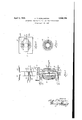
- Figure 1 shows my apparatus in its; prefer ed. o m c mple e i h; v p r ng h ri 2 and; dephlegmating. cti il -ele a on;
- p anl oking om b t e vaporizing chamber 2; downward showing in outline; a; furnace: '24 for, heating the tubes 6 and -v 3 isa planswnfrom be heh e in t b s-
- Thelmain chamber; 1; is an-elongated tubular member-expanding into a vaporizing Qham rrsec ion ne 2; nd n n ng aboveit asa dephlegmating section or tower 11.
- the mainchamber has init, in the center of; -it s:circulatingzone, a centrifugal or other suitablety-pe of impeller pump 3 operated through asha ft 4 by an external motor 5, or any other suitable means.
- The-mainchamber also has nearits bottom valve controlled means for; introducing; acharging stock; 9 valve controlled; means for introducinga catalyst, steam, gas or a treatment agent, or acombinationof two-or more of: them 10, and valve controlled means ll for withdrawing solids and heavier hydrocarbons that, may gravitate to the settling zone 22;; also 1 valve ontro le means; 2 rt e. upp r r r g he ,main h mb r e pw p zi g h mber,
- This main chamber is entirely encircled with heating and circulating tubes ,6 running from the upper to the lower part ofthe chamber see Fig. 1 orvice versa, placed nextto each other, asshown in Fig. 3, with other encircling rows above or below, asappears in Fig. 1 -at a pointmarked 6, said tubes-being l en asmany in number and as. closetogether as may be mechanicallyv expedient, and the pump beingplaced midway between the upper and lower openings ofsaid tubes into saidmain chamber 1.
- These tubes are-heatedand the hydrocarbons in, them brought to cracking temperature by any suitable means, such ,as ,a fire-box or -furnace flue.
- main chamber 1 Above the main chamber 1, and :in-continuation of; it, .is the vaporizingohamber, section or,-zo ne2, shown in Fig. 1 asgan-eflQn. .gateddrum 2 placed horizontallyt'o-the main chamber 1' with means-1a for cleaningfit, which chamber, section or zone may; be Qfia'ny form on shape desired, provided it is in direct and open communication with -the main h mber i l 1 Above the vaporizing chamber, sectionjor zone-is a dephlegmating sectionor tower;1,- a continuation of the m'ainchamberl withbaf ⁇ fies 15, valve controlled means ,for.
- the charging stock is fed continuously. or' intermittently into the 7 main chamber 1 through 9 and forcediby the pump 3. into the lower opening 8 of the tube'sfand thence through them. and outj oftheir upper openings 7 into the part ofthe main chamber 1 above the pump which drawsfthe fluid downward and keepsrit in. continuous "rapid circulation. portion o'iithe lighter hydrocarbons, however, pass upwardinto the va n r ngb h quidt n h h-by I separation; Condensate is not withdrawn or refluxed as when an independent 'dephlegmator or separator is used, but it at once gravitationally returns to the main bodyof hydrocarbon liquid, thus conserving heat that 7 would otherwise be lost in transit.
- a new and improved apparatus for producing low-boiling point hydrocarbons from higher-boiling-point hydrocarbons comprising a main tubular chamber encircled in whole or in part by a plurality of substantially concentric tubes opening out of said main chamber near one end and extendingto an opening into said main chamber nearthe other end, a centrifugal or other impeller pump or other suitable means of inducing controlled circulationthrough said tubes and chamber placed intermediate the entrances to and exits from said tubes insaid main chamber, means of producing and maintainof introducing charging stock to said main chamber, means of introducing a catalyst, steam, gas or a treatment agent oraacombination .of two or more of them, a section in the main chamber below thetubes where solids, may settle and heavy hydrocarbons may gather, means of withdrawing solids and heavy hydrocarbons, a vaporizing section, zone or chamber in or asan extension of or addition to the main chamber so situated as to be relatively free of circulatioma dep
- said vaporizing chamber being laterally en large'dfto provide for a surface exposure of liquid hydrocarbon of greater area than the cross sectional area of themain chamber
- a new and improved apparatus for distilling and cracking hydrocarbons consisting of a main tubular chamber of vertically elongated formation and of substantiall uniform cross-sectional area fromend to en encircled in whole or in part'by a plurality of substantially concentric tubes opening out of said main chamber near its upper end and extending to and opening into said main chamber near its lower end, means'for producing and maintaining temperatures in said tubes and chamber conduclve to, cracking,
- a vaporizing chamber superposed upon and opening directly into the main chamber above the entrances of the concentric tubes, said vaporizing chamber being laterally enlarged to provide for a surface exposure of liquid hydrocarbon of greater area than the cross sectional area of the main chamber.
- a new and improved apparatus for distilling and cracking hydrocarbons consisting of a main tubular chamber of vertically elongated formation and of substantially uniform cross-sectional area from end to end, encircled in Whole or in part by a plurality of substantially concentric tubes opening out of said main chamber nearits upper end and extending to and opening into said main chamber near its lower end, means for producing and maintaining temperatures in said tubes and chamber conducive to cracking, a vaporizing chamber superposed upon and opening directly into the main chamber abovethe entrances of the concentric tubes, said vaporizing chamber being laterally enlarged to provide for a surface exposure of liquid hydrocarbon of greater area than the cross sectional area of the main chamber, and a dephlegmator section of vertically elongated formation and superposed upon a and opening directly into the vaporizing chamber and adapted to gravitationally discharge condensate directly to the surface of the liquid in the vaporizing chamber.
Landscapes
- Chemical & Material Sciences (AREA)
- Oil, Petroleum & Natural Gas (AREA)
- Physics & Mathematics (AREA)
- Thermal Sciences (AREA)
- Engineering & Computer Science (AREA)
- Chemical Kinetics & Catalysis (AREA)
- General Chemical & Material Sciences (AREA)
- Organic Chemistry (AREA)
- Production Of Liquid Hydrocarbon Mixture For Refining Petroleum (AREA)
Description
April 5, 1932- H.T. DARLINGTON 1,352,150
APPARATUS AND PROCESS FOR TREATING HYDROCARBONS Filed April 25, 1927 IMPILLER PUMP IN V EN TOR.
a /ya);
A TTORNEYS Patented Apr. 5, 1932 STATES PATENT, OFFICE] HOMER T; DARLINGTON QZE wnsr: onnsrnngrnnnsywenra, ASSIGNOR rq mm BaSCHUSTEB, 'rr nsrnn, or aomnr rrlrnvors;
APPARATUSAND rnocnss ronrnnarnvq HY nn'oeARBons- Application-filed. April 25,1927. Serial No. 186,465.
unit or incombination andco-operation with avapo-rizi-ngchamber or zone and a deph-legw matin section united-to ether as inte ral g i .n e
partsof one apparatus which, in either it'orm,
19 has very decided advantages, both in operation and in results attained, over other types ofapparatus, as will hereinafter more fully ppea 7 ,While my process is independent .of-the apparatus, thje apparatusto be described is so peculiarly adapted to it that, a previous description of theapparatus willhelp greatly immaking; clear; the characteristics of the process. 1
th -drawings Figure 1 shows my apparatus in its; prefer ed. o m c mple e i h; v p r ng h ri 2 and; dephlegmating. cti il -ele a on;
ig-=2 is a. p anl oking om b t e vaporizing chamber 2; downward showing in outline; a; furnace: '24 for, heating the tubes 6 and -v 3 isa planswnfrom be heh e in t b s- Thelmain chamber; 1; is an-elongated tubular member-expanding into a vaporizing Qham rrsec ion ne 2; nd n n ng aboveit asa dephlegmating section or tower 11. The mainchamberhas init, in the center of; -it s:circulatingzone, a centrifugal or other suitablety-pe of impeller pump 3 operated through asha ft 4 by an external motor 5, or any other suitable means. The-mainchamber also has nearits bottom valve controlled means for; introducing; acharging stock; 9 valve controlled; means for introducinga catalyst, steam, gas or a treatment agent, or acombinationof two-or more of: them 10, and valve controlled means ll for withdrawing solids and heavier hydrocarbons that, may gravitate to the settling zone 22;; also 1 valve ontro le means; 2 rt e. upp r r r g he ,main h mb r e pw p zi g h mber,
section; on zone; for selectively; withdrawing lighter fluid-hydrocarbons; and valve, con- I trolled means for introducing liquids 13. r
This main chamber is entirely encircled with heating and circulating tubes ,6 running from the upper to the lower part ofthe chamber see Fig. 1 orvice versa, placed nextto each other, asshown in Fig. 3, with other encircling rows above or below, asappears in Fig. 1 -at a pointmarked 6, said tubes-being l en asmany in number and as. closetogether as may be mechanicallyv expedient, and the pump beingplaced midway between the upper and lower openings ofsaid tubes into saidmain chamber 1. These tubes are-heatedand the hydrocarbons in, them brought to cracking temperature by any suitable means, such ,as ,a fire-box or -furnace flue.
Above the main chamber 1, and :in-continuation of; it, .is the vaporizingohamber, section or,-zo ne2, shown in Fig. 1 asgan-eflQn. .gateddrum 2 placed horizontallyt'o-the main chamber 1' with means-1a for cleaningfit, which chamber, section or zone may; be Qfia'ny form on shape desired, provided it is in direct and open communication with -the main h mber i l 1 Above the vaporizing chamber, sectionjor zone-is a dephlegmating sectionor tower;1,- a continuation of the m'ainchamberl withbaf} fies 15, valve controlled means ,for. withdraw; ingke'rosene, etc, 17 cooling trays or-coils 16, valve controlledmeans foradmi-tti'ngylS) and -withd,rawing 18,- cooling fluid, valve controlled meansi2l'for admitting cool liquid hydrocarbonto aid in dephlegmation, and valve controlled means; 20 for withdrawing vapors-'and'gases, I 4
Inoperation, the charging stock is fed continuously. or' intermittently into the 7 main chamber 1 through 9 and forcediby the pump 3. into the lower opening 8 of the tube'sfand thence through them. and outj oftheir upper openings 7 into the part ofthe main chamber 1 above the pump which drawsfthe fluid downward and keepsrit in. continuous "rapid circulation. portion o'iithe lighter hydrocarbons, however, pass upwardinto the va n r ngb h quidt n h h-by I separation; Condensate is not withdrawn or refluxed as when an independent 'dephlegmator or separator is used, but it at once gravitationally returns to the main bodyof hydrocarbon liquid, thus conserving heat that 7 would otherwise be lost in transit.
I have found that continuous cycling in the manner described prevents carbon deposits,
, hastens cracking and 'results in the production in a single operation of a larger proportion of gasoline than is obtainable by other means. I also find that the introduction of a catalyst, steam, gas or a treating agent, or, in some instances, of a combination of two or more of them, is very advantageous.
It will be noted that a distinctive characteristic of my apparatus as described is the forcefulcirculation of hydrocarbons from one end of a common chamber through a plurality of concurrent-approximately semi-circular tubes back to the other end of the common chamber where hydrocarbons from the several tubes are commingled and in the main pumped to the other end and again circulated and-this repeatedly. This methodof circulation is an essential feature of my process which ordinarily also includes the other subsequent methods of treatment already described.
ring temperature, means I claim v s 1. A new and improved apparatus for producing low-boiling point hydrocarbons from higher-boiling-point hydrocarbons comprising a main tubular chamber encircled in whole or in part by a plurality of substantially concentric tubes opening out of said main chamber near one end and extendingto an opening into said main chamber nearthe other end, a centrifugal or other impeller pump or other suitable means of inducing controlled circulationthrough said tubes and chamber placed intermediate the entrances to and exits from said tubes insaid main chamber, means of producing and maintainof introducing charging stock to said main chamber, means of introducing a catalyst, steam, gas or a treatment agent oraacombination .of two or more of them, a section in the main chamber below thetubes where solids, may settle and heavy hydrocarbons may gather, means of withdrawing solids and heavy hydrocarbons, a vaporizing section, zone or chamber in or asan extension of or addition to the main chamber so situated as to be relatively free of circulatioma dephlegmating and separating section, zone or tower in or as an eXten-,
sion of or addition to the main chamber, with the said main chamber, vaporizing section, zone or chamber and dephlegmating and separating section, zone or tower in such relation to each other that they will be in comlation through said smaller columns and back to the main column and there discharging and commingling the hydrocarbon liquid of the smaller columns with the main column to repeatedly continue the circulation, and in maintaining above thezone of circulation a non-circulating body of hydrocarbon presenting an exposed surfaceflto induce vaporization, said exposed surface being of substantially greater varea than the cross sectional area of the'main' column, and in directly discharging the vaporsinto-a dephlegmating section disposed immediately above the vaporizing zone and in position to provide for the gravitational return of condensate directly to'the liquid surfacefof. the hydrocarbon in the vaporizing zone without the liquid being withdrawn from the apparatus. j I 3. A new and improved apparatus for'distilling and cracking hydrocarbons consisting of a main tubular chamber of substantially uniform cross-sectional area from end toend,
encircled in whole or in part by a plurality of substantially concentric tubes opening out of said main chamber near its upper end and extending to and opening into-said main chamber near its lower end, means for producing and maintaining temperatures in said tubes and chamber conducive to cracking,
and a vaporizing chamber superposed upon and opening directly into the main chamber above the entrances of theconcentric tubes,
said vaporizing chamber being laterally en large'dfto provide for a surface exposure of liquid hydrocarbon of greater area than the cross sectional area of themain chamber,
I 4. A new and improved apparatus for distilling and cracking hydrocarbons consisting of a main tubular chamber of vertically elongated formation and of substantiall uniform cross-sectional area fromend to en encircled in whole or in part'by a plurality of substantially concentric tubes opening out of said main chamber near its upper end and extending to and opening into said main chamber near its lower end, means'for producing and maintaining temperatures in said tubes and chamber conduclve to, cracking,
and a vaporizing chamber superposed upon and opening directly into the main chamber above the entrances of the concentric tubes, said vaporizing chamber being laterally enlarged to provide for a surface exposure of liquid hydrocarbon of greater area than the cross sectional area of the main chamber.
5. A new and improved apparatus for distilling and cracking hydrocarbons consisting of a main tubular chamber of vertically elongated formation and of substantially uniform cross-sectional area from end to end, encircled in Whole or in part by a plurality of substantially concentric tubes opening out of said main chamber nearits upper end and extending to and opening into said main chamber near its lower end, means for producing and maintaining temperatures in said tubes and chamber conducive to cracking, a vaporizing chamber superposed upon and opening directly into the main chamber abovethe entrances of the concentric tubes, said vaporizing chamber being laterally enlarged to provide for a surface exposure of liquid hydrocarbon of greater area than the cross sectional area of the main chamber, and a dephlegmator section of vertically elongated formation and superposed upon a and opening directly into the vaporizing chamber and adapted to gravitationally discharge condensate directly to the surface of the liquid in the vaporizing chamber.
HOMER T. DABLINGTON.
Priority Applications (1)
| Application Number | Priority Date | Filing Date | Title |
|---|---|---|---|
| US186465A US1852150A (en) | 1927-04-25 | 1927-04-25 | Apparatus and process for treating hydrocarbons |
Applications Claiming Priority (1)
| Application Number | Priority Date | Filing Date | Title |
|---|---|---|---|
| US186465A US1852150A (en) | 1927-04-25 | 1927-04-25 | Apparatus and process for treating hydrocarbons |
Publications (1)
| Publication Number | Publication Date |
|---|---|
| US1852150A true US1852150A (en) | 1932-04-05 |
Family
ID=22685067
Family Applications (1)
| Application Number | Title | Priority Date | Filing Date |
|---|---|---|---|
| US186465A Expired - Lifetime US1852150A (en) | 1927-04-25 | 1927-04-25 | Apparatus and process for treating hydrocarbons |
Country Status (1)
| Country | Link |
|---|---|
| US (1) | US1852150A (en) |
-
1927
- 1927-04-25 US US186465A patent/US1852150A/en not_active Expired - Lifetime
Similar Documents
| Publication | Publication Date | Title |
|---|---|---|
| US1852150A (en) | Apparatus and process for treating hydrocarbons | |
| US2312719A (en) | Cracking process | |
| US1914914A (en) | Method for vapor phase cracking of oil | |
| US1763609A (en) | Process of treating hydrocarbon oils | |
| US1664977A (en) | Art of distilling lubricating oils | |
| US1964686A (en) | Method for vapor phase cracking of oil | |
| US2160239A (en) | Art of converting hydrocarbons | |
| US1936298A (en) | Treating hydrocarbon oils | |
| US2126204A (en) | Conversion of hydrocarbon oils | |
| US2036965A (en) | Cracking system | |
| US2460463A (en) | Process for the noncatalytic cracking of a hydrocarbon oil | |
| US1357277A (en) | Process for treatment of hydrocarbon oils | |
| US1924602A (en) | Method and apparatus for distillation of hydrocarbons | |
| US2164132A (en) | Process and apparatus for distilling oil | |
| US1418713A (en) | Process of and apparatus for cracking oils | |
| US1796507A (en) | Process and apparatus for converting petroleum oil | |
| US1934873A (en) | Treatment of hydrocarbon oils | |
| US1789072A (en) | Art of cracking hydrocarbons | |
| US1917705A (en) | Cracking hydrocarbon oils | |
| US2285744A (en) | Method for coalescing foamy oil | |
| US1933574A (en) | Treating hydrocarbon oil | |
| US2023063A (en) | Process of cracking petroleum hydrocarbons | |
| US1828466A (en) | Oil refining | |
| US2008550A (en) | Process of cracking petroleum oils | |
| US1962595A (en) | Art of cracking hydrocarbons |