US1852101A - Cylinder-forming machine - Google Patents
Cylinder-forming machine Download PDFInfo
- Publication number
- US1852101A US1852101A US330804A US33080429A US1852101A US 1852101 A US1852101 A US 1852101A US 330804 A US330804 A US 330804A US 33080429 A US33080429 A US 33080429A US 1852101 A US1852101 A US 1852101A
- Authority
- US
- United States
- Prior art keywords
- die
- strong
- crossheads
- closed
- strut member
- Prior art date
- Legal status (The legal status is an assumption and is not a legal conclusion. Google has not performed a legal analysis and makes no representation as to the accuracy of the status listed.)
- Expired - Lifetime
Links
Images
Classifications
-
- B—PERFORMING OPERATIONS; TRANSPORTING
- B21—MECHANICAL METAL-WORKING WITHOUT ESSENTIALLY REMOVING MATERIAL; PUNCHING METAL
- B21D—WORKING OR PROCESSING OF SHEET METAL OR METAL TUBES, RODS OR PROFILES WITHOUT ESSENTIALLY REMOVING MATERIAL; PUNCHING METAL
- B21D5/00—Bending sheet metal along straight lines, e.g. to form simple curves
- B21D5/01—Bending sheet metal along straight lines, e.g. to form simple curves between rams and anvils or abutments
- B21D5/015—Bending sheet metal along straight lines, e.g. to form simple curves between rams and anvils or abutments for making tubes
Definitions
- That machine is a continuation-impart. That machine is adapted for bend ng averyheav-y steel plate,
- My present invention adapts a machinefof to a somewhat different the rapid production of" cylinders from thinner material and diameter. For example,
- the type of cylinder forming machine comprehended in my co-pending-apphcation above referred to'compris es an anvil ly projecting crossheads near its ends, having its-ends mounted: iii-the for-med with a longitudinal groove in its workin face, a movable die-carrying frame downwar a die crosshe ads and disposed norn'ially parallel with the anvil.
- the die is adapted to press the sheetp 'ogressively into the groove.
- the present invention includes an improved dievsupportingi means that-permits the work to be removed without swing ing the'die outwardly from its-normalposition. "The structure-also includes EL-I18W k-H1Cl of cross-headattached to the strong-back.
- This cross-head embodies wha't I-term a die keeper, being a-hin-ged member adapted to anend-"of'the be opened and closed so of the dieandafliord operatively engage when-closed.
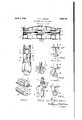
- FIG. .1 is a side elevation of a tube-forming. machine embodying" myfimprovement.
- Fig. 2 is an enlarged fragmentary end View showing the die in raised position.
- FIG. 3 is a view of the gatemctuatingmechanisni. as seen from above.
- FigsAt, 5 and 6 are respectively sectional details showingthe various steps inthezforining of a tube.
- Fig. '1 a perspective view partly 111;S6C- tion showing the hanger. connection: between 1 the delivery end 0f the dierand :the' strongback.
- strut member 1 which 15 being shaped by the Fig. 8 is-a perspective view partly in secthe leaves of the keeper.
- a machine embodying my invention consists in the anvil A whose upper face is formed with a longitudinal groove A, a working frame, which consists in a vertically reciprocatable strong-back B having crossheads C at its ends carried upon suitable guide-rods E and a die D carried by the crossheads, the die being below and spaced from the strong-back B to permit the curved part of the plate to enter between them.
- the tube to be formed is of light material, but very long and of small diameter, it becomes essential to support the die D throughout substantially its entire length so as to avoid all possibility of upward springing. It is not absolutely necessary that the is inserted between the top of the die and the tend as a continuous piece throughout the entire length of the die D, but the points of support should be sufficiently close together to prevent any appreciable springing of the die.
- a strut member 1 which is preferably a plate standing edgewise on the top face 2 of the die made substantially flat for that purpose.
- the strut member 1 is carried by the strongback B and is held upright, that is, perpendicular, to the flat face 2 of die D by lugs 3 or other suitable means on the strong-back.
- ugs engage a pair of flanges 4 on the strut plate 1, .as shown in Figs. 4 to 6, so the latter may have limited sidewise movement on the upper face of the die, to prevent its binding when it is engaged by the edges 5 of the tube at the completion of the bending operation, as shown in Fig. 6.
- movement can be limited, as desired, by means of adjusting screws 3a, threaded in lugs 3, as shown in Fig. 4.
- the strut member 1 effectually prevents springing of the die D and transmits directly from the die to the strong-back all stresses that would otherwise cause the die to bow upward in the middle under load.
- the delivery end of the die is held suspended from the strong-back by means of adie-supporting hanger-6, preferably in the Since the work is manner shown in Fig. 7 to be removed from the die off .endwise in the direction 1, that portion 6a of the hanger, which spans the space 7 between the strong-back B and die is made thinner than the slit between the longitudinal edges 5 of the formed tube.
- the tube when being stripped off from the anvil passes the hanger 6 the same as it passes strut member 1, shown in Fig. 6.
- the hammer 6 supports the delivery end of the die but while the work die D the working D by stripping it strong-backshall eX- times connected together by an exceedin
- a keeper 8 9, made so as to be opened and closed.
- This die keeper is adapted when closed to operatively grasp an end of the die D and when opened is adapted to release the die and swing out of the way to afford passage ing its removal from the die.
- a suitable form of keeper which is shown in Figs. 2, 3 and 8. It consists in a pair of hinged leaves 8,. 9, the knuckles of which are provided with flanges 10 by which they are swiveled in counterbores provided at the lower ends of the crossheads C.
- the free edge of each leaf is formed with a recess 11 to fit overthe end of the die which may be shaped for the pur pose, as shown at 12 in Fig. 7 or if desired the recess 11 in the leaf may be made to conform to the shape of the body of the die itself.
- each leaf can be opened and closed simultaneously by any suitable means, as for ex.- ample that shown in Fig. 3, where each leaf is provided with anoutwardly projecting arm 13 having a link 14 pivoted to it, the other ends of the links being pivoted together after the manner of a toggle joint which can be actuated by an operating bar 15 to open and close the leaves, as indicated by the dotted and full lines.
- the leaves are closed and the sheet of material is 'fed in between the die and anvil, as shown in Figs. 4, 5 and 6, the successive downward pressing movements of the die causing the;- material to curl around it.
- one margin is operated on, as shown in Fig. v4,
- the hinged members or keepers 8, 9 are opened outwardly, as indicated by the dotted lines in Fig. 3, after which the work can be stripped from the die, the thin portion 6a of the hanger shown in Fig. 7 permitting its passage.
- a tube forming machine including vertically reciprocatably crossheads, a strongback connecting the same and a die carried by said crossheads below and spaced from said strong-back, the top of the die formed to present a substantially flat bearing face, a strut member inserted between said face and strong-back, means on the strong-back holding the strut member in operative position yet permitting its limited sidewise movement upon said bearing face, a die-supporting hanger connecting the delivery end of the die with the strong-back, that portion of the hanger which spans the space separating the strong-back and die formed to be received between the longitudinal edges of the formed tube, a die keeper pivotally mounted on one of said crossheads so as to be opened and closed and adapted when closed to operatively engage an end of said die and when opened adapted to release the die to aiiord passage for the finished work during its removal from the die.
- a tube forming machine including vertically reciprocatable crossheads, a strongback, a die carried by said crossheads below and spaced from said strong-back, a strut member inserted between said die and strongback, means on the strong-back holding the strut member in operative position yet permitting its limited sidewise movement, a hanger connecting the delivery end of the die with the strong-back, that portion of the hanger which spans the space separating the strong-back and die formed to be received between the longitudinal edges of the formed tube.
- a tube forming machine including l vertically reciprocatable crossheads, a strongback, a die carried by said crossheads below and spaced from said strong-back, a strut member inserted between said die and strongon the strong-back holding the strut member in operative position yet permitting its limited sidewise movement, for the purposes set forth.
- a tube forming machine including vertically reciprocatable cross heads, a a die carried by said crossheads below and spaced from said strong-back, a strut member inserted between said die and strong-back capable of limited sidewise movement, a die-supporting hanger connecting the delivery end of the die with the strong-back,
- a die keeper pivotally mounted on one of said crossheads so as to be opened and closed and adapted when closed to operatively engage an end of said die and when opened adapted to release the die to afford passage for the finished work during its removal from the c 1e.
- a die keeper comprising a pair of oppositely hinged leaves pivotally mounted on one of said crossheads so as to be opened and closed and adapted when closed to operatively engage an end of said die and when opened adapted to release the die to afford passage for the finished work during its removal from the die, and means for supporting the delivery end of the die from the crosshead.
Landscapes
- Engineering & Computer Science (AREA)
- Mechanical Engineering (AREA)
- Bending Of Plates, Rods, And Pipes (AREA)
Description
April 5, 1932. J. F. L. BAKER 1,852,101
CYLINDER FORMING MACHINE Filed Jan. 7, 1929 F762 6 Join FLfia/er INVENTOR plates,
-as water pipes and the like.
" abovereferredto isshown and Patented Apr. 5, 1932 '5! LINE TEE T; S a
- ear en'i" erriee JOHN F; L.-;IBA.KER; :OF SAG-INAW; MICHIGAN, -ASSIGNOR T WICKES BOILER CO.',OF
iSAGINAW, .MICHIGAN; A:,GOBPORATION OF: MICHIGAN CYLINDER-FORMING MACHINE Applicationfiled January 7,."1929;
' 'This invention relates to a machine for forming heavy-steel sheets, light and medium or 81111118.! mater1al,- into tubes, such A cylinderrforming niachine of the kind 1 described and claimed-as to its broader aspects in my copending application Serial No.17 0,191, filed February 23, 1 927.; patented No.1y69890l'of'wvhichthe-present application January-1h, 1929,
is a continuation-impart. That machine is adapted for bend ng averyheav-y steel plate,
Whose thickness is, say,
that general class .kind 'of work. namely,
say, two inches thick, into a tube, say,- ten feet long and about forty'i'nches diameter.
My present invention adapts a machinefof to a somewhat different the rapid production of" cylinders from thinner material and diameter. For example,
accuratecylindrical form a sheet-of-steel five-eighths inch, width four feet,-length forty feet produeing a cylinder fifteen-inches diameter, the forming operation being performed in such manner that the longitudinal'edges of the finished *tube will be slightly separatedand parallel to each other ready to be closed together in a subsequent operation on diiferent machine and finished by welding or riveting.
In general the type of cylinder forming machine comprehended in my co-pending-apphcation above referred to'compris es an anvil ly projecting crossheads near its ends, having its-ends mounted: iii-the for-med with a longitudinal groove in its workin face, a movable die-carrying frame downwar a die crosshe ads and disposed norn'ially parallel with the anvil. The die is adapted to press the sheetp 'ogressively into the groove. The strongsback and comprising a strong-back having 'die are spaced 1 apart to receive the curved part of the sheet between them; Means is provided -for..aetua" ng the die-carrying fra1ne,. 11S=sfOT example, a hydraulic engine,
and-provision is made for 'det'aching an end "of the;- die: fromthe' frame removal ofthe completed cylinder.
to :permit ithe The specific means illustrated'in my previous application above referred to for remova -ing the finished work" die and adapted to semi No. 330,804.
consists of a pivotal connection between the reclproeating frame and an endof the die,-the other endofthe die adapted to be swung out from-its normal positionin the frame to permit 'removal'of the completed cylinder.
1 The previous application also describes the use of removable struts connectingthe strengback and die,- in order to preventany appreciable springing'of the dielwhen subjected to heavy duty.
'My present inventionem-bodies certain improvements in the formofthedie, i-n theconstruction and arrangement ofthe strutsbetween the die and-the means for supporting strong-back and in-the thecompleted work is 7 being stripped from it. -Moreover,
the present invention includes an improved dievsupportingi means that-permits the work to be removed without swing ing the'die outwardly from its-normalposition. "The structure-also includes EL-I18W k-H1Cl of cross-headattached to the strong-back.
This cross-head embodies wha't I-term a die keeper, being a-hin-ged member adapted to anend-"of'the be opened and closed so of the dieandafliord operatively engage when-closed.
as to release the end "passage for the finishedwbrli during its removal from the die. 3 With the foregoing and certain other ob.- jects in view which specification, my invention comprises the'devices described and claimed. and the equivalents thereof. A In the drawings Fig. .1 is a side elevation of a tube-forming. machine embodying" myfimprovement.
Fig. 2 is an enlarged fragmentary end View showing the die in raised position.
1 Fig. 3 is a view of the gatemctuatingmechanisni. as seen from above.
: FigsAt, 5 and 6 are respectively sectional details showingthe various steps inthezforining of a tube.
Fig. '1 's a perspective view partly 111;S6C- tion showing the hanger. connection: between 1 the delivery end 0f the dierand :the' strongback.
the end ofthe die wh-ile will appear later in the tion, of one of strut member 1 which 15 being shaped by the Fig. 8 is-a perspective view partly in secthe leaves of the keeper.
As is clearly shown in the drawings, a machine embodying my invention consists in the anvil A whose upper face is formed with a longitudinal groove A, a working frame, which consists in a vertically reciprocatable strong-back B having crossheads C at its ends carried upon suitable guide-rods E and a die D carried by the crossheads, the die being below and spaced from the strong-back B to permit the curved part of the plate to enter between them.
Since the tube to be formed is of light material, but very long and of small diameter, it becomes essential to support the die D throughout substantially its entire length so as to avoid all possibility of upward springing. It is not absolutely necessary that the is inserted between the top of the die and the tend as a continuous piece throughout the entire length of the die D, but the points of support should be sufficiently close together to prevent any appreciable springing of the die. I have, therefore, shown as an example a strut member 1 which is preferably a plate standing edgewise on the top face 2 of the die made substantially flat for that purpose. The strut member 1 is carried by the strongback B and is held upright, that is, perpendicular, to the flat face 2 of die D by lugs 3 or other suitable means on the strong-back. The
ugs engage a pair of flanges 4 on the strut plate 1, .as shown in Figs. 4 to 6, so the latter may have limited sidewise movement on the upper face of the die, to prevent its binding when it is engaged by the edges 5 of the tube at the completion of the bending operation, as shown in Fig. 6. movement can be limited, as desired, by means of adjusting screws 3a, threaded in lugs 3, as shown in Fig. 4.
The strut member 1 effectually prevents springing of the die D and transmits directly from the die to the strong-back all stresses that would otherwise cause the die to bow upward in the middle under load.
The delivery end of the die is held suspended from the strong-back by means of adie-supporting hanger-6, preferably in the Since the work is manner shown in Fig. 7 to be removed from the die off .endwise in the direction 1, that portion 6a of the hanger, which spans the space 7 between the strong-back B and die is made thinner than the slit between the longitudinal edges 5 of the formed tube. The tube when being stripped off from the anvil passes the hanger 6 the same as it passes strut member 1, shown in Fig. 6.
- Whenever apiece of work from the machine, the hammer 6 supports the delivery end of the die but while the work die D the working D by stripping it strong-backshall eX- times connected together by an exceedin The sidewise of the arrow, Fig.
is being removed load is transmitted from the crosshead to the die by means of a keeper 8, 9, made so as to be opened and closed. This die keeper is adapted when closed to operatively grasp an end of the die D and when opened is adapted to release the die and swing out of the way to afford passage ing its removal from the die.
I have devised a suitable form of keeper which is shown in Figs. 2, 3 and 8. It consists in a pair of hinged leaves 8,. 9, the knuckles of which are provided with flanges 10 by which they are swiveled in counterbores provided at the lower ends of the crossheads C. The free edge of each leaf is formed with a recess 11 to fit overthe end of the die which may be shaped for the pur pose, as shown at 12 in Fig. 7 or if desired the recess 11 in the leaf may be made to conform to the shape of the body of the die itself. When the two leaves are closed, as shown in Fig. 2, they form practically integral parts of the crosshead C, so the strongback and the end 12 of the dieare at such s y strong connection capable of withstanding the enormous working pressures that are transmitted through it from the hydraulic engine to the die. Thus when the leaves 8, 9 are closed the entire crosshead is, for practical purposes, the equivalent of a unitary casting, but when the leaves are opened they afiiord free passage through which the tube can be pulled lengthwise and removed from the die D. I
The leaves can be opened and closed simultaneously by any suitable means, as for ex.- ample that shown in Fig. 3, where each leaf is provided with anoutwardly projecting arm 13 having a link 14 pivoted to it, the other ends of the links being pivoted together after the manner of a toggle joint which can be actuated by an operating bar 15 to open and close the leaves, as indicated by the dotted and full lines.
When the machine is in operation the leaves are closed and the sheet of material is 'fed in between the die and anvil, as shown in Figs. 4, 5 and 6, the successive downward pressing movements of the die causing the;- material to curl around it. Preferably one margin is operated on, as shown in Fig. v4,
, and then the other margin, as shown in Fig.
5, and lastly the middle part as shown in 6, requiring three operations in all to finish. The final shape and position of the finished sheet is indicated in Fig. 6, where the two longitudinal edges 5, 5 are spaced apart, presenting a slit through which the strut member 1 projects. If the work happens to 're-. quire it. a slight sidewise movement of the strut member may take place in the lugs 3, thus preventing binding or cramping, and keeping the die D free from any lateral strains that might otherwise be brought upon for the finished work durback and means strong-b ack,
it by the pressure of the work against the side of the strut member 1.
To remove the work the hinged members or keepers 8, 9 are opened outwardly, as indicated by the dotted lines in Fig. 3, after which the work can be stripped from the die, the thin portion 6a of the hanger shown in Fig. 7 permitting its passage.
Having thus described my invention, what I claim and desire to secure by Letters Patent is:
1. In a tube forming machine including vertically reciprocatably crossheads, a strongback connecting the same and a die carried by said crossheads below and spaced from said strong-back, the top of the die formed to present a substantially flat bearing face, a strut member inserted between said face and strong-back, means on the strong-back holding the strut member in operative position yet permitting its limited sidewise movement upon said bearing face, a die-supporting hanger connecting the delivery end of the die with the strong-back, that portion of the hanger which spans the space separating the strong-back and die formed to be received between the longitudinal edges of the formed tube, a die keeper pivotally mounted on one of said crossheads so as to be opened and closed and adapted when closed to operatively engage an end of said die and when opened adapted to release the die to aiiord passage for the finished work during its removal from the die.
2. In a tube forming machine including vertically reciprocatable crossheads, a strongback, a die carried by said crossheads below and spaced from said strong-back, a strut member inserted between said die and strongback, means on the strong-back holding the strut member in operative position yet permitting its limited sidewise movement, a hanger connecting the delivery end of the die with the strong-back, that portion of the hanger which spans the space separating the strong-back and die formed to be received between the longitudinal edges of the formed tube.
3. In a tube forming machine including l vertically reciprocatable crossheads, a strongback, a die carried by said crossheads below and spaced from said strong-back, a strut member inserted between said die and strongon the strong-back holding the strut member in operative position yet permitting its limited sidewise movement, for the purposes set forth.
l. In a tube forming machine including vertically reciprocatable cross heads, a a die carried by said crossheads below and spaced from said strong-back, a strut member inserted between said die and strong-back capable of limited sidewise movement, a die-supporting hanger connecting the delivery end of the die with the strong-back,
a die keeper pivotally mounted on one of said crossheads so as to be opened and closed and adapted when closed to operatively engage an end of said die and when opened adapted to release the die to afford passage for the finished work during its removal from the c 1e.
5. In a tube forming machine including vertically movable crossheads, a strong-back, a die carried by said crossheads below and spaced from said strong-back, a die keeper comprising a pair of oppositely hinged leaves pivotally mounted on one of said crossheads so as to be opened and closed and adapted when closed to operatively engage an end of said die and when opened adapted to release the die to afford passage for the finished work during its removal from the die, and means for supporting the delivery end of the die from the crosshead.
In testimony whereof, I affiX my signature.
JOHN F. L. BAKER.
Priority Applications (1)
| Application Number | Priority Date | Filing Date | Title |
|---|---|---|---|
| US330804A US1852101A (en) | 1929-01-07 | 1929-01-07 | Cylinder-forming machine |
Applications Claiming Priority (1)
| Application Number | Priority Date | Filing Date | Title |
|---|---|---|---|
| US330804A US1852101A (en) | 1929-01-07 | 1929-01-07 | Cylinder-forming machine |
Publications (1)
| Publication Number | Publication Date |
|---|---|
| US1852101A true US1852101A (en) | 1932-04-05 |
Family
ID=23291400
Family Applications (1)
| Application Number | Title | Priority Date | Filing Date |
|---|---|---|---|
| US330804A Expired - Lifetime US1852101A (en) | 1929-01-07 | 1929-01-07 | Cylinder-forming machine |
Country Status (1)
| Country | Link |
|---|---|
| US (1) | US1852101A (en) |
Cited By (7)
| Publication number | Priority date | Publication date | Assignee | Title |
|---|---|---|---|---|
| US2426260A (en) * | 1944-01-05 | 1947-08-26 | Kaiser Fleetwings Inc | Method of deforming sheet material on predetermined spaced lines |
| US2486428A (en) * | 1947-12-02 | 1949-11-01 | John M Minor | Sheet metal forming brake |
| US2505718A (en) * | 1947-06-26 | 1950-04-25 | Clearing Machine Corp | Tube forming machine with longitudinally movable core |
| US2520165A (en) * | 1946-03-27 | 1950-08-29 | Ott Albert | Roll-shaper supporting bracket |
| US2591085A (en) * | 1949-06-06 | 1952-04-01 | Basalt Rock Company Inc | Machine for bending sheets |
| US5365767A (en) * | 1992-03-23 | 1994-11-22 | Steelcase Inc. | Brake press arrangement |
| JP2020006387A (en) * | 2018-07-05 | 2020-01-16 | ナカジマ鋼管株式会社 | Manufacturing device of round steel pipe and round steel pipe manufacturing facility |
-
1929
- 1929-01-07 US US330804A patent/US1852101A/en not_active Expired - Lifetime
Cited By (7)
| Publication number | Priority date | Publication date | Assignee | Title |
|---|---|---|---|---|
| US2426260A (en) * | 1944-01-05 | 1947-08-26 | Kaiser Fleetwings Inc | Method of deforming sheet material on predetermined spaced lines |
| US2520165A (en) * | 1946-03-27 | 1950-08-29 | Ott Albert | Roll-shaper supporting bracket |
| US2505718A (en) * | 1947-06-26 | 1950-04-25 | Clearing Machine Corp | Tube forming machine with longitudinally movable core |
| US2486428A (en) * | 1947-12-02 | 1949-11-01 | John M Minor | Sheet metal forming brake |
| US2591085A (en) * | 1949-06-06 | 1952-04-01 | Basalt Rock Company Inc | Machine for bending sheets |
| US5365767A (en) * | 1992-03-23 | 1994-11-22 | Steelcase Inc. | Brake press arrangement |
| JP2020006387A (en) * | 2018-07-05 | 2020-01-16 | ナカジマ鋼管株式会社 | Manufacturing device of round steel pipe and round steel pipe manufacturing facility |
Similar Documents
| Publication | Publication Date | Title |
|---|---|---|
| JPS6356010B2 (en) | ||
| US2679278A (en) | Apparatus for assembling tank bodies | |
| US3174322A (en) | Machines for working sheet metal | |
| US1852101A (en) | Cylinder-forming machine | |
| US3910092A (en) | Metal expanding machine | |
| US1761888A (en) | Method and means for upsetting sheet metal | |
| US2700408A (en) | Method of forming a pipe | |
| US1958447A (en) | Pipe bend and method and apparatus for making the same | |
| US1045089A (en) | Ridge-roll-forming die. | |
| US1666380A (en) | Apparatus for making chains | |
| US2476596A (en) | Bending and anvil die for fmgmt | |
| US1849054A (en) | Apparatus for the manufacture of metal tubes | |
| US2944583A (en) | Die structure for tangent bending of corrugated sheet metal | |
| US3045967A (en) | Hollow blades and manufacture thereof | |
| US2268628A (en) | Machine for bending metal gutter hangers | |
| US1406004A (en) | Metal-working machine | |
| US2451307A (en) | Clamp for frame straightening machines | |
| US4930329A (en) | Installation for producing metal girders | |
| US1955356A (en) | Device for producing joints on tubular members | |
| US2428890A (en) | Metal stretching press which straightens and moves work edges into drawing chucks | |
| US2911932A (en) | Tube making machine | |
| US2036745A (en) | Bending machine | |
| US1775760A (en) | Pipe-bending machine and method | |
| US3543558A (en) | Culvert end section forming machine | |
| US1788241A (en) | Machine for bending trouser hooks |