US1852089A - Bolt anchor - Google Patents
Bolt anchor Download PDFInfo
- Publication number
- US1852089A US1852089A US533918A US53391831A US1852089A US 1852089 A US1852089 A US 1852089A US 533918 A US533918 A US 533918A US 53391831 A US53391831 A US 53391831A US 1852089 A US1852089 A US 1852089A
- Authority
- US
- United States
- Prior art keywords
- integral
- shield
- holt
- shielcl
- slots
- Prior art date
- Legal status (The legal status is an assumption and is not a legal conclusion. Google has not performed a legal analysis and makes no representation as to the accuracy of the status listed.)
- Expired - Lifetime
Links
Images

Classifications
-
- F—MECHANICAL ENGINEERING; LIGHTING; HEATING; WEAPONS; BLASTING
- F16—ENGINEERING ELEMENTS AND UNITS; GENERAL MEASURES FOR PRODUCING AND MAINTAINING EFFECTIVE FUNCTIONING OF MACHINES OR INSTALLATIONS; THERMAL INSULATION IN GENERAL
- F16B—DEVICES FOR FASTENING OR SECURING CONSTRUCTIONAL ELEMENTS OR MACHINE PARTS TOGETHER, e.g. NAILS, BOLTS, CIRCLIPS, CLAMPS, CLIPS OR WEDGES; JOINTS OR JOINTING
- F16B13/00—Dowels or other devices fastened in walls or the like by inserting them in holes made therein for that purpose
- F16B13/04—Dowels or other devices fastened in walls or the like by inserting them in holes made therein for that purpose with parts gripping in the hole or behind the reverse side of the wall after inserting from the front
- F16B13/08—Dowels or other devices fastened in walls or the like by inserting them in holes made therein for that purpose with parts gripping in the hole or behind the reverse side of the wall after inserting from the front with separate or non-separate gripping parts moved into their final position in relation to the body of the device without further manual operation
- F16B13/0858—Dowels or other devices fastened in walls or the like by inserting them in holes made therein for that purpose with parts gripping in the hole or behind the reverse side of the wall after inserting from the front with separate or non-separate gripping parts moved into their final position in relation to the body of the device without further manual operation with an expansible sleeve or dowel body driven against a tapered or spherical expander plug
-
- F—MECHANICAL ENGINEERING; LIGHTING; HEATING; WEAPONS; BLASTING
- F16—ENGINEERING ELEMENTS AND UNITS; GENERAL MEASURES FOR PRODUCING AND MAINTAINING EFFECTIVE FUNCTIONING OF MACHINES OR INSTALLATIONS; THERMAL INSULATION IN GENERAL
- F16B—DEVICES FOR FASTENING OR SECURING CONSTRUCTIONAL ELEMENTS OR MACHINE PARTS TOGETHER, e.g. NAILS, BOLTS, CIRCLIPS, CLAMPS, CLIPS OR WEDGES; JOINTS OR JOINTING
- F16B13/00—Dowels or other devices fastened in walls or the like by inserting them in holes made therein for that purpose
- F16B13/04—Dowels or other devices fastened in walls or the like by inserting them in holes made therein for that purpose with parts gripping in the hole or behind the reverse side of the wall after inserting from the front
- F16B13/06—Dowels or other devices fastened in walls or the like by inserting them in holes made therein for that purpose with parts gripping in the hole or behind the reverse side of the wall after inserting from the front combined with expanding sleeve
- F16B13/063—Dowels or other devices fastened in walls or the like by inserting them in holes made therein for that purpose with parts gripping in the hole or behind the reverse side of the wall after inserting from the front combined with expanding sleeve by the use of an expander
- F16B13/066—Dowels or other devices fastened in walls or the like by inserting them in holes made therein for that purpose with parts gripping in the hole or behind the reverse side of the wall after inserting from the front combined with expanding sleeve by the use of an expander fastened by extracting a separate expander-part, actuated by the screw, nail or the like
- F16B13/068—Dowels or other devices fastened in walls or the like by inserting them in holes made therein for that purpose with parts gripping in the hole or behind the reverse side of the wall after inserting from the front combined with expanding sleeve by the use of an expander fastened by extracting a separate expander-part, actuated by the screw, nail or the like expanded in two or more places
Definitions
- JERSEYA CORPORAIION' OF NEW JERSEY Our invention relates to holt m1cl1orS.
- Our invention further relatesio holt an eher inclucling expancllng n1eans formecl eriginally in one integral piece, wit-h insegral conneeting me1nbe1s liolcling them together, said integral connectecl inennbers being broken in situ.
- Our invention further rel2ies 130 an integral holt anchor fonnecl 0f an integ1al shielcl 0T cage aml expancling means connectecl to saicl shielcl er sage by break-able 1neahs, saicl breakable means being of sufficient 'strength to witnstanclhanelling ancl transportation.
- ur invention iurtl1er relates to U. nmch-ine type expansion in whicli the shielcl er cage.
- anal expancling means are all formeclintegral the expanding means beingbroken from tl1e shielcl er Gage in siiu, anal t;elescope anal expancl the shield 01 sage by the [ziel of the usual machine bolt.
- Our invention more particulanly 1elaees 150 such a holt anchor as Clescribehl above, in Wlii0li tl1e-1i ial integral pa1fis a1e so arrangecl filmt when the integral connecting members are br0l;en in siu, devise canbe 110 relative rotary movement becween the shielcl o1 cage anal the exp-ancling means, Whether the eX pancling means be one 01' m01e laterally 1novable mernbers.
- Our invention further relaces t0 such a holt ancl1orin whicl1 tl1e sl1ielcl o1 cage is provielecl witl1 one 01 more lateral slots forming tines, ancl one er more integral i'igil expanding 1;nembers providecl wisn guicling, 01, g'ulllllg ?.ncl expanaling, 1neans exteneling into such slots, more O1 lese, and brealzable conneetions behveen ehe shielcl an.
- tne guicling means 01 guicling und expancling means, so that tl1ere Will be no -clanger of misalignment between the shielel und tne expancling rnember, 0r
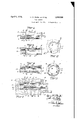
- Fig. l is a plan view of One forma of bolii ancher, macle in accorclance W1tl1 our inven.-
- FIG. 2 is an encl view looking to tl1e left of Fig. l;
- Fig. 3 is a vertical section on line 33 of 1 looking in tlie cli1ection 0l i:l1e arrows; Eig. 4 1s a longitudinal sect wn 011 l1ne l4 0fliig. 2
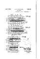
- Fig. 7 is a vertical section, similzirto Fig.;6,
- breaking bl1e connecting mexiibers Fig. 8 is a vercical section,- sirnilar 130 Fig..7, J
- Fig. 9 is a vertical sction 0f a moclifieatien.
- Fig, 14 is a vertical Section of "Ou1 holt an- Chor mountecl in a hole about to be expanclecl by a l1amlner
- Fig. 15 is a vertical secsion holt anchor expanclecl.
- breakable connections which are adapted 10 be broken in sic-u, connect splines with the shield. These splines are caston the expand ing member o1 mernbers and are located initially, partially, in sl0ts in the cage o1 shield, so that there cari loe 110 misalignment of the cage 'or shield when the breakable connecuions are broken.
- 1 is the integral rigid holt anchor formed of the expansible rnember 2 and the expanding Ine1nber '3, rigidly held t'ogether by the integral breakable connectin'g rnembers 18, 18.
- these breakable connectingmembefs 18, 18, are runners, and are not brokenuntil the holt anchor is expanded in situ.
- the exp'ansible me1nber 2 is a Gage or shield provided with one or more slots 5, 5, four being preferab the bead 6.
- the expanding me1nber 3 is cast at the same time as the shield 0r cage 2 and is rigidly held to it by the breakable connecting members, or runners, 18, 18.
- the member 3 is provided with an exterior conical surface 7, and With one or 1nore splines 8, 8, there preierably, though not necessarily, being the sa1ne number of splines as there are slots 5, 5 in the sage 01 shield.
- These splines 8,8 are preierably, though not necessarily, form-ed as wedges so that after the breakable connections 18, 18 are broken in situ, the wedges are forced down the slocs 5, 5 towards the head 6, and force the Walls of' the slots apart,-
- a hole 10 is fonned in the Wall 11.
- the rigid integral holtanchor, Figures 1 and 2 is Ehen inserted in the hole 10.
- the 'machine holt 15 is tl1en passed throngh a holel6 snpported 17, and is threaded intothe rigid ab all times the splines 8, 8 position, with their cooperthe male threads 14 0f in the work to be' nut and the shield drilled or otherwise inaznovable cone nut 3, Figure 6.
- An1ong other aclvanta ges tl1is facilitates the even fiow 01 the metal in the mo1ild, because there are eight passages fo1 the'metal;toollow between the sluelcl:and cone nut.
- olos1ng each of the slots 5
- 5 wit ha spline anclloreakable:con-- nectionsbetw een t-he splines anal the shield'a very l1gh, streng ancl r1g1clyonstruot10Il-1s fo1med.
- Gast integral with the shielclil00 is a cone nut 101having a conical surface 105, in all respects sumlarto the s-mgle -type maclnne bolt enchor previously clescriloed.
- cone nut- 10-1 1s prowclecl whentenor screw threacls 112, thetsame as m the other form.
- lt has a conloal exterior surface 114 aclapted 1 tocooperace wit-h the flaring surface 111. It is also provided with splines115, 115 the very encls ofwhioh,11, 116, arecast W1tll1Il the :slots 103, 103,one spli ne for eaoh sloc.
- the opening in the mold forming the scop 101 serves to assisfthe quick flow of the T0 save the expense of drilli1ig a hole of 1 full depth such 215 shown 111 F1gures 7 Sind 8, wo may-drill a hole oflss depththan the length of the holt anchor, so that when the holt anchor is loc'atecl, a portion of it Will -.protrucle from the hole, Fig. 1 1.
- ecl t-o force as to lo1ows o1 21 hamnaet, 126, the breakable connections willbe brokeh anc1 the eone nut forcecl into the shielcl as shown in 3 Fig.. 15. 111 this osition the holt Eanchor Will bepre-set ancl pre-expancled without the 'aid of the holt 15.
- Such a holt may loe lat'er usecl t0 support the'vvork, not shown in these figures, ancl,if neoessary, the bonclor g'grip 01 the holt anchor may be' increased loy: ro-
- a bolt anchor having an integral shielcl provicletl W1th cooperatmg mterlock1ng snrfaces, an integral expancling 1nernbel pro viclecl With interlocking surfaces, ancl integral breakable 1neans holding said interlocking snrfaces 011 the shielcl and expancling member in line With eaelr other anc1 also holcling the integral shielcl ancl integral expancling member rigidlytogether in their.
- a new article 0f manufacture Coniprising a cast bolt anchor having an integral shielcl pr0vided with one or more slots and tines, an integralexpancling 1ne1nber provid ed With one 0r more integral splines, ai1d breakable runners connecting the splines with the integral shield, theentire bolt anchor being a single integral casting.
- a new article 0it' manu'facture comprising a cast bolt anchor having an integral shield pr0violed with one ormore slots and tines, an integral expancling mennber providecl with one or more int'egralsplinesthe end of one spline being rigiclly held within a slot in the sliielcl, ancl bre akable runners connecting the spline witli each side 0f the slot, the entire bolt anchor being a single in- 12.
- a new article 0f manufa(zture cornpris ing a cast bolt anchdr having an integral shield providecl with one or more slots ai1d tines, an integral expanding member pro- Vided withone 0r more integral wedges, and
Landscapes
- Engineering & Computer Science (AREA)
- General Engineering & Computer Science (AREA)
- Mechanical Engineering (AREA)
- Surgical Instruments (AREA)
Description
April 1932- H w. PLEISTER ET AL 1,852,089
BOLT ANCHOR Filed April SO, 1931 3 Sheets-Sheet 1 ATTORN EY April 1932- H. w. PLEISTER ET AL 15209 BOLT ANCHOR Filed April SO. 1931 3 Sheets-Sheet 2 ATTONEY April 5, 1932. w. PLEISTER ET AL BOLT ANCHOR Filed April 50, 1931 3 Sheets-Sheet 3 l INVEN A NEY Patentenl pr. 5, 1932 ;E-IENRY V. PLEISTER}OF WESTFIELD, AND 'JOHN.KARITZKY O5 GABWOOID', NEW- ASS'IG'NOBS 'ID HENRY B. NEWHA'LL COIEvPORATION, CF GARVJ'OOD,
JERSEY,
NEW
JERSEYA CORPORAIION' OF NEW JERSEY Our inventionrelates to holt m1cl1orS.
Our invention further relatesio holt an eher inclucling expancllng n1eans formecl eriginally in one integral piece, wit-h insegral conneeting me1nbe1s liolcling them together, said integral connectecl inennbers being broken in situ.
Our invention further rel2ies 130 an integral holt anchor fonnecl 0f an integ1al shielcl 0T cage aml expancling means connectecl to saicl shielcl er sage by break-able 1neahs, saicl breakable means being of sufficient 'strength to witnstanclhanelling ancl transportation.
ur invention iurtl1er relates to U. nmch-ine type expansion in whicli the shielcl er cage. anal expancling means are all formeclintegral the expanding means beingbroken from tl1e shielcl er Gage in siiu, anal t;elescope anal expancl the shield 01 sage by the [ziel of the usual machine bolt.
Our invention more particulanly 1elaees 150 such a holt anchor as Clescribehl above, in Wlii0li tl1e-1i ial integral pa1fis a1e so arrangecl filmt when the integral connecting members are br0l;en in siu, obere canbe 110 relative rotary movement becween the shielcl o1 cage anal the exp-ancling means, Whether the eX pancling means be one 01' m01e laterally 1novable mernbers.
Our invention further relaces t0 such a holt ancl1orin whicl1 tl1e sl1ielcl o1 cage is provielecl witl1 one 01 more lateral slots forming tines, ancl one er more integral i'igil expanding 1;nembers providecl wisn guicling, 01, g'ulllllg ?.ncl expanaling, 1neans exteneling into such slots, more O1 lese, and brealzable conneetions behveen ehe shielcl an. tne guicling means, 01 guicling und expancling means, so that tl1ere Will be no -clanger of misalignment between the shielel und tne expancling rnember, 0r
nembers, when broken in sicu.
Our invention "Eurtl1er relates t0 cereziin cembina-tions, sub-eombinations, articles 0f manufacture aml cletails of consjtruction, all o'f wl1icn will beniore fully hereinaiter :le scribel an l pointecl out in tne claims.
In -tl1e figures we have shown elifierent embocliments cf 0ur inventin, tl1e szunereference numerals refer to similar parts of the several figures.
man adaptecl to 1931. Serial N0. 533,918.
Fig. l is a plan view of One forma of bolii ancher, macle in accorclance W1tl1 our inven.-
tion;
2 is an encl view looking to tl1e left of Fig. l;
; Fig. 3 is a vertical section on line 33 of 1 looking in tlie cli1ection 0l i:l1e arrows; Eig. 4 1s a longitudinal sect wn 011 l1ne l4 0fliig. 2
; 1s a vert1cal sect1on 011 l1ne 55 of 0 23 7 Fig. 6 s a vercal sect1on of a mach1ne type holt anchor 0f Fig. l, mountecl m a hole,
9J1Cl abou t0 be expanclecl by a machine holt;
Fig. 7 is a vertical section, similzirto Fig.;6,
breaking bl1e connecting mexiibers Fig. 8 is a vercical section,- sirnilar 130 Fig..7, J
illustrqting :helelesc0}3ing acticin and thefull expans1on cf the expansion bolt;
Fig. 9 is a vertical sction 0f a moclifieatien.
Fig, 14 is a vertical Section of "Ou1 holt an- Chor mountecl in a hole about to be expanclecl by a l1amlner Fig. 15 is a vertical secsion holt anchor expanclecl.
Our inveneion relates t0 sinnplifyii1g an l cheapening anchors. vF01 purposes oi:illustration we have shown in our drawings a Single arid (101ible type m2ichine holt eXpansi'on, though, Of
showin@ the course, our invention. is n0t eobelimiteclto:=
these paricularfexrnis 0'f expa1isionbolts.
ln tl1e 0rcliniry machine. type expansion ehe sl1ell 01 eage is forrnecl 0f tWO er m01e split spring mng. Intliesingle type Inahine 10 expzuision, a tappecl c0ne n'nt has to be asse'm- Vertical section dftl1e duble:
Fig. 9, about to -be' aesion ancl -the -ehe. cost of manufactnr1ng holt bled and held within the shell or case by the same split spring ring. In the double machine type there is, in acldition, an unthreaded cone sleeve held in the other end 015 the shell-or cage by a second Split spring ring. In transportation and in rough handling these assernbled parts are apt 120 become disconnected, and, in so1ne instances one 0r more of the parts n1ight bec01ne lost, leading 150 the discard 0f the entire holt anchon Among other advantages of our invention We avoid all the cost of assembling difl"erent parts, the cost of the split spring rings, o1 other securing 1neans, any loss 0f parts in transportation or handling, and cheapen the cost of manufacture.
By 0111 invention We cast, or otherwise form, a complete holt anchor W11311 the shield or Ca e and ex 3andin member or niembers as one article, connected together wit-h breakable connections adapted to be broken in situ.
As Will more fully hereinafter appear our breakable connections, which are adapted 10 be broken in sic-u, connect splines with the shield. These splines are caston the expand ing member o1 mernbers and are located initially, partially, in sl0ts in the cage o1 shield, so that there cari loe 110 misalignment of the cage 'or shield when the breakable connecuions are broken.
We also preferably, though not necessarily, form the splines as wedges, so that in addition to performing the function of splines they assist in forcing the sides of the slots apart, thereby increasingthe grip 0r hold of the holt anchor in support;
In Figures 1 130 8, inclsive, We have shown a Single type machine expansion; in Figures 9 to 13, inclusive, a d0uble type machine expansion, and in Figures 14 and 15 a single type machine expansion, expanded by a hans- 1ner, or sirnilar tool, in a shallow hole. It 1s, of course, 150 be understood that a doulole type machine expansion, such as illustrated 111 Figures 9 to 13 inelusive, could also be preset, in the same manner in a shallow hole less than its length.
For purposes of illustration and a Wall or other suitable description We will describe our holt anchors as ceist,v they may be otherwise though, of course, formed.
In the single type machine expansion, 1 is the integral rigid holt anchor formed of the expansible rnember 2 and the expanding Ine1nber '3, rigidly held t'ogether by the integral breakable connectin'g rnembers 18, 18. When cast, Whieh is the preferred methodof manufacture, these breakable connectingmembefs 18, 18, are runners, and are not brokenuntil the holt anchor is expanded in situ.
The exp'ansible me1nber 2 is a Gage or shield provided with one or more slots 5, 5, four being preferab the bead 6.
y employed, extending from The expanding me1nber 3 is cast at the same time as the shield 0r cage 2 and is rigidly held to it by the breakable connecting members, or runners, 18, 18. The member 3 is provided with an exterior conical surface 7, and With one or 1nore splines 8, 8, there preierably, though not necessarily, being the sa1ne number of splines as there are slots 5, 5 in the sage 01 shield. These splines 8,8 are preierably, though not necessarily, form-ed as wedges so that after the breakable connections 18, 18 are broken in situ, the wedges are forced down the slocs 5, 5 towards the head 6, and force the Walls of' the slots apart,-
thereby inaterially assisting in forming a powerful grip 01 hold between the shield 2 and the sides 9 of the hole 10 in the Wall o1 other support 11. This action assists the rnain expanding action of'the cone nut 7 cooperating with the flaring opening 12 of the shield. After our holt anchor is cast the 1nember 3 is tapped l tive rotation betvveen the cone nut and the shield 2, because are in operative ating slots 5, 5.
In use a hole 10 is fonned in the Wall 11. The rigid integral holtanchor, Figures 1 and 2, is Ehen inserted in the hole 10. The 'machine holt 15 is tl1en passed throngh a holel6 snpported 17, and is threaded intothe rigid ab all times the splines 8, 8 position, with their cooperthe male threads 14 0f in the work to be' nut and the shield drilled or otherwise inaznovable cone nut 3, Figure 6. By screwing upon the head of the holt 15 the breakable connections 18, 18 betwee n the ends 4, 4 0f the dilferent splines 8, 8 and the shield or Gage 2 18, 18, pe'rmits the cone nut 3 to radially spread he ends o1 the tines 20, 20, Fig. 8.
8, 8 to the shield 2 are 7 5 being now open, where they had preworsly been closed by the ends 4, 4 of "the spl1nes 8, 8 and the breakable connectins are bro-ken, Fignre 7. By continuing to rotate the holt 15 it Will be seen that there Abthesame filme the siclewallsr of th'e slots 5, 5 are forcecl apartby the splines8, 8 which are preferably, though not-necessarily, formed as weclges. This.ac tionof course, maerially' assists the main grip o1 boncl formecl by the cone nut oooperatingwiththe flaring surfaoe 12 of the shielrl.hf
It is, also, to be noted, that when the holt zmchor 3's cast each breakable connection 18, 18is a runner connecting each spline 8 with the shield at two points. If the shield is proviclecl W111l1 four slots 5, 5, there Will loe eight runners or breakable connections, two for each spline ancl each slot. An1ong other aclvanta ges tl1is facilitates the even fiow 01 the metal in the mo1ild, because there are eight passages fo1 the'metal;toollow between the sluelcl:and cone nut.- By olos1ng=each of the slots 5, 5 wit=ha spline anclloreakable:con-- nectionsbetw een t-he splines anal the shield'a very l1gh, streng ancl r1g1clyonstruot10Il-1s fo1med.-
Our invenion may also be emploj ed-with a clouble type machine expansiofl. Wo have sl1o*wn one example of such a construct1on m F1gures 9 50,13 1nclus1Ve.
vicled witl1. a central fing 01 stop 101, and two sets I" slots-l02, l02, and 103, 103.
Gast integral with the shielclil00 is a cone nut 101having a conical surface 105, in all respects sumlarto the s-mgle -type maclnne bolt enchor previously clescriloed. This=cone 11112 is proviclecl with splmesl06, 106, ohe very ends 107, 107 of thei splines10, 108 beim-g located within theslots 102,102, the1e being ehe usua1 two runners, er breakable-sonnentions, 108,108 beaween the ends 107, 107- of eachspline 106a11cl the shielcl 100; theends of the splinesv anal ehe breakable conneotions close each slot 102, 102.-
The=shielcl orcage 100 is provicledwith two con-ical surface 105015 the cone 11115104, when The the breakalole connections are broken. cone nut- 10-1 1s prowclecl whentenor screw threacls 112, thetsame as m the other form.
A1; the other end 0f Ehe shield 01 cage 100 an integral sleeve1131s oast, thesame es the cone nut 104, witl1 the exceptionihat, this sleeveis not prov1decl Wih sorew threacls.
lt has a conloal exterior surface 114 aclapted 1 tocooperace wit-h the flaring surface 111. It is also provided with splines115, 115 the very encls ofwhioh,11, 116, arecast W1tll1Il the : slots 103, 103,one spli ne for eaoh sloc.
Eaoh of thesplines ofuhe sleeve 113 :is (3011- nectecl b two brealzable con-nections 117 117,
" with the'shield 100.
111 use this cloulole type machine expansion is placed in he hole 10 in the Wall 11. A macnine bol is then passecl through the hole 16 in Ehe work 17 ancl -screwed intothe '1igicl nui. 105, passing freely through the unvthreadecl sleeve 113, Fig. 12. By t henscrewing up 011 theloolt 15 thebreakableconnections between the splines on lahe cone nut 104 auch the unthreaclecl sleeve 113, Will be broken.
There Will bei no misalignment, however,
becauee the splines -0h the cone nut and the-splines1l5 on the sleeve 113have their encls cast within thei1 respec-tive cooperao-v.
orbetween the shielcl ancl theunthreaded sleeve- 113.
The splineson both the= cone nut fandl.thefl sleeve 113 being preieraolywedge shapecl,
be. Walls of the slots 102 and 103, Will =oe -forcecl apart, thereby materiallyhdcling to the main grip 01 boncl.formecl loy the cone nut 105 cooperatmgt.W1th:theflamngur= face o1 the shield 100, und the..cone sleeve 113 cooperating with the flaring sur. face 111 of theehield, Fig. 8.
The opening in the mold forming the scop 101, serves to assisfthe quick flow of the T0 save the expense of drilli1ig a hole of 1 full depth such 215 shown 111 F1gures 7 sind 8, wo may-drill a hole oflss depththan the length of the holt anchor, so that when the holt anchor is loc'atecl, a portion of it Will -.protrucle from the hole, Fig. 1 1. VVhen this protruclingportion is :subject=;
ecl t-o force, as to lo1ows o1 21 hamnaet, 126, the breakable connections willbe brokeh anc1 the eone nut forcecl into the shielcl as shown in 3 Fig.. 15. 111 this osition the holt Eanchor Will bepre-set ancl pre-expancled without the 'aid of the holt 15. Such a holt may loe lat'er usecl t0 support the'vvork, not shown in these figures, ancl,if neoessary, the bonclor g'grip 01 the holt anchor may be' increased loy: ro-
tating a holt 15,not shown in Fig.- 15, clr2LW-5 ing the cone nut still further into theshield. Of eourse the clouble type machine expansion showriin Figures 9 t'o 13, inclusive, can be expanded by a hammer, 01' a similar tool, in the same manner.
Our holt 'anchors a.re for use 1I1"WilllS,
fioorsyceilixigs, or supports of masonry,con=- crete, brick, terra cotta, stone, or other ma terial 1IlWlllCll 1t 1s 1mposs1lole d1reotly screw a screw, or dr1ve a nzul or sp1ke.
l/Vhile we have illustrated and clescribed a machine holt cooperating with the oone nut,
it is 01 course, to be understoool that our 1I1-' vention anal our claims cover a holt having lag screw threacls{ or a njr;other. fo1"m of threacls, an l tha't the :cone nut W1ll be pro vicled with cooperating female threads.
ing a bolt anchor having an integral shielcl provicletl W1th cooperatmg mterlock1ng snrfaces, an integral expancling 1nernbel pro viclecl With interlocking surfaces, ancl integral breakable 1neans holding said interlocking snrfaces 011 the shielcl and expancling member in line With eaelr other anc1 also holcling the integral shielcl ancl integral expancling member rigidlytogether in their.
initial position and aclaptecl to perrnit the interloeking surfaces 011 the integral shielcl and integral expanding 1nember t0 positively cooperate with each other t0 prevent 1n1salign1nentof said xne1nbers.
2. Ina bolt anchor the con1bination 0f an expans1ble shielcl prov1clecl vv1th t1nes and slots, an integral expand1ng menaber 11g1dly l1-elcl t0- the shielcl by splines closing the slots, ancl breakabl-e connections between the splines 21I1Cl the shielcl.
3. In a bolt ancl1or the cornbiriation of an expansible sl1ielcl proviclecl with tines ancl sl0ts, an integral expancling 1ne1nber rigiclly helcl to the shielcl by splines extencling int0 the slots,*1nore er less, ancl breakable conne@ tions between the splines ancl the shielcl.
4. In a bolt anchor the Cornbination of an expansible shield proviclecl with tines and slots, an integral expancling member rigiclly held t0 the shield by wedges closing the slots, ancl breakable cnnections between the weclges ancl the shield.
5. In a blt ancho-r the cornbination of an expansible 'shield proviclecl with. tines and slots, an integral expancling 1ne1nber rigidly helrl t0 the snielcl by wedges extending int0 the slots,1nore or lese, and breakable connections between the weclges ancl the shielcl.
6. Tl1e combination in adouble type maclnn-e expanslon of an 1ntegral slnelcl hav1ng cooperatmg 1nterlo0k1ng surfaces for a cone nut ancl a cone sleeve, an integral exparicling cene nut promcled W1th 1nterloclnng surfaces to cooperatewith those carriecl by the shielcl, integral breakable connections l1olcling the saicl co-operating interlocking suriaces 0n the conenut in line with the c0-operating interloclring surfac es on the shield antl also holding the cone nut and shield rigiclly together ncl adaptecl t0 pern1it the interlocking snr-' faces 0n the shielcl anal cone nut to positively cooperate witl1 ea.ch other t0 prevent mis alignxnent, a cone sleeve providecl. with interl0cking surfaces to c00peratewith those carriecl by the shielclancl integral breakable connections holclingthe saicl co-operating interlocking surfaces 011 the cone sleeve in line Wltll the. co-operat1ng 1nterlock1ng surftces tegral casting.
sleeve closing saicl slots in the shielcl, ancl breakable connections between said splines and said shield.
8. The comloination in a double type ma chine expansion 0f an integral shield having cooperating slots at each encl O f the shield, an integral cone mit at one encl of the shield and an integral cone sleeve at the other end of the shielcl, splines on the cone nut anal cone sleeve extending into saicl slots in the shielcl, ancl breakable connections between said splines and saicl shield.
9. The combination in a cloubletype nachine expansion 0f an integral shield having cooperating slots at each enol of. the shielol, an integral cone nut at one end of the shield ancl an integral cone sleeve at the other encl 0f the shielcl, wedges on the cone nut and cone sleeve closing said slots in the shielcl, and breakable connections between said weclges ancl said shield.
10. A new article 0f manufacture Coniprising a cast bolt anchor having an integral shielcl pr0vided with one or more slots and tines, an integralexpancling 1ne1nber provid ed With one 0r more integral splines, ai1d breakable runners connecting the splines with the integral shield, theentire bolt anchor being a single integral casting.
11. A new article 0it' manu'facture comprising a cast bolt anchor having an integral shield pr0violed with one ormore slots and tines, an integral expancling mennber providecl with one or more int'egralsplinesthe end of one spline being rigiclly held within a slot in the sliielcl, ancl bre akable runners connecting the spline witli each side 0f the slot, the entire bolt anchor being a single in- 12. A new article 0f manufa(zture cornpris ing a cast bolt anchdr having an integral shield providecl with one or more slots ai1d tines, an integral expanding member pro- Vided withone 0r more integral wedges, and
breakable runners, connecting the. wedges with the integral shield, the entire bolt anchor being a Single integral casti1ig. V
HENRY W. PLEISTER. JOHN KARITZKY.
Priority Applications (1)
| Application Number | Priority Date | Filing Date | Title |
|---|---|---|---|
| US533918A US1852089A (en) | 1931-04-30 | 1931-04-30 | Bolt anchor |
Applications Claiming Priority (1)
| Application Number | Priority Date | Filing Date | Title |
|---|---|---|---|
| US533918A US1852089A (en) | 1931-04-30 | 1931-04-30 | Bolt anchor |
Publications (1)
| Publication Number | Publication Date |
|---|---|
| US1852089A true US1852089A (en) | 1932-04-05 |
Family
ID=24127972
Family Applications (1)
| Application Number | Title | Priority Date | Filing Date |
|---|---|---|---|
| US533918A Expired - Lifetime US1852089A (en) | 1931-04-30 | 1931-04-30 | Bolt anchor |
Country Status (1)
| Country | Link |
|---|---|
| US (1) | US1852089A (en) |
Cited By (8)
| Publication number | Priority date | Publication date | Assignee | Title |
|---|---|---|---|---|
| US2941439A (en) * | 1957-01-30 | 1960-06-21 | Illinois Tool Works | Rivet and integral expander pin connected thereto by area of limited cross section |
| US3345900A (en) * | 1964-10-15 | 1967-10-10 | Standard Pressed Steel Co | Blind fastener |
| US5704746A (en) * | 1997-01-30 | 1998-01-06 | Illinois Tool Works Inc. | Plastic fastener for threaded blind aperture |
| US5816759A (en) * | 1997-05-08 | 1998-10-06 | Illinois Tool Works Inc. | Expansion anchor and method therefor |
| WO2000060245A1 (en) * | 1999-04-06 | 2000-10-12 | Fischerwerke Artur Fischer Gmbh & Co. Kg | Expansion anchor |
| US6702534B2 (en) * | 2001-03-07 | 2004-03-09 | Horst Filipp Gmbh | Spreader dowel |
| US20060241618A1 (en) * | 2003-02-03 | 2006-10-26 | Stryker Trauma S.A. | Implantable orthopaedic device |
| US20100193657A1 (en) * | 2009-02-02 | 2010-08-05 | Therin Laney | Tie down assembly for a vehicle |
-
1931
- 1931-04-30 US US533918A patent/US1852089A/en not_active Expired - Lifetime
Cited By (11)
| Publication number | Priority date | Publication date | Assignee | Title |
|---|---|---|---|---|
| US2941439A (en) * | 1957-01-30 | 1960-06-21 | Illinois Tool Works | Rivet and integral expander pin connected thereto by area of limited cross section |
| US3345900A (en) * | 1964-10-15 | 1967-10-10 | Standard Pressed Steel Co | Blind fastener |
| US5704746A (en) * | 1997-01-30 | 1998-01-06 | Illinois Tool Works Inc. | Plastic fastener for threaded blind aperture |
| US5816759A (en) * | 1997-05-08 | 1998-10-06 | Illinois Tool Works Inc. | Expansion anchor and method therefor |
| US6293743B1 (en) | 1997-05-08 | 2001-09-25 | Illinois Tool Works Inc. | Expansion anchor and method therefor |
| WO2000060245A1 (en) * | 1999-04-06 | 2000-10-12 | Fischerwerke Artur Fischer Gmbh & Co. Kg | Expansion anchor |
| US6702534B2 (en) * | 2001-03-07 | 2004-03-09 | Horst Filipp Gmbh | Spreader dowel |
| US20060241618A1 (en) * | 2003-02-03 | 2006-10-26 | Stryker Trauma S.A. | Implantable orthopaedic device |
| US7686837B2 (en) * | 2003-02-03 | 2010-03-30 | Stryker Trauma S.A. | Polyaxial locking implantable orthopedic fixation device |
| US20100193657A1 (en) * | 2009-02-02 | 2010-08-05 | Therin Laney | Tie down assembly for a vehicle |
| US8602379B2 (en) * | 2009-02-02 | 2013-12-10 | Therin Laney | Tie down for a vehicle assembly |
Similar Documents
| Publication | Publication Date | Title |
|---|---|---|
| US3008552A (en) | Structural fastener | |
| US1808318A (en) | Bolt anchor and method | |
| US4642009A (en) | Wall plug | |
| US3443474A (en) | Blind fastener | |
| US4720224A (en) | Sleeve anchor | |
| US2690693A (en) | Fastener with expanding spring gripping means | |
| US1852089A (en) | Bolt anchor | |
| US3411398A (en) | Blind fastener | |
| US2006813A (en) | Self-locking drive expansion fastener | |
| US3695045A (en) | Rock bolts | |
| US3657955A (en) | Blind fastener with expandable collar | |
| JPS5919709A (en) | Blind bolt | |
| US2914983A (en) | Explosively driven fastener having axially collapsible radially expandable locking sleeve | |
| US3322449A (en) | Blind fastener system | |
| DE2328447A1 (en) | SELF-DRILLING BLIND RIVET DEVICE | |
| US2479075A (en) | Screw locking means | |
| US2725915A (en) | Self-locking stud insert | |
| US3596948A (en) | Blind fastener and blind fastener system | |
| US1982915A (en) | Safety joint | |
| GB2027153A (en) | Anchor bolt assembly | |
| US2343283A (en) | Screw fastening with self-riveting head | |
| US2139167A (en) | Bolt anchor | |
| US4537541A (en) | Anchor bolt assembly | |
| US3257891A (en) | Wedge type expansion bolt | |
| US3381567A (en) | Mine roof bolt |