US1852070A - Injector - Google Patents
Injector Download PDFInfo
- Publication number
- US1852070A US1852070A US37127729A US1852070A US 1852070 A US1852070 A US 1852070A US 37127729 A US37127729 A US 37127729A US 1852070 A US1852070 A US 1852070A
- Authority
- US
- United States
- Prior art keywords
- valve
- injector
- disk
- seat
- stem
- Prior art date
- Legal status (The legal status is an assumption and is not a legal conclusion. Google has not performed a legal analysis and makes no representation as to the accuracy of the status listed.)
- Expired - Lifetime
Links
- XLYOFNOQVPJJNP-UHFFFAOYSA-N water Substances O XLYOFNOQVPJJNP-UHFFFAOYSA-N 0.000 description 55
- 230000003137 locomotive effect Effects 0.000 description 17
- 239000012530 fluid Substances 0.000 description 13
- 238000010438 heat treatment Methods 0.000 description 13
- 238000007664 blowing Methods 0.000 description 6
- 230000001276 controlling effect Effects 0.000 description 4
- 230000001105 regulatory effect Effects 0.000 description 4
- 230000011664 signaling Effects 0.000 description 2
- 230000000881 depressing effect Effects 0.000 description 1
- 230000000694 effects Effects 0.000 description 1
- 230000002706 hydrostatic effect Effects 0.000 description 1
- 230000000266 injurious effect Effects 0.000 description 1
- 238000009434 installation Methods 0.000 description 1
- JCCNYMKQOSZNPW-UHFFFAOYSA-N loratadine Chemical compound C1CN(C(=O)OCC)CCC1=C1C2=NC=CC=C2CCC2=CC(Cl)=CC=C21 JCCNYMKQOSZNPW-UHFFFAOYSA-N 0.000 description 1
- 239000000203 mixture Substances 0.000 description 1
- 238000012986 modification Methods 0.000 description 1
- 230000004048 modification Effects 0.000 description 1
- 239000013641 positive control Substances 0.000 description 1
Images
Classifications
-
- F—MECHANICAL ENGINEERING; LIGHTING; HEATING; WEAPONS; BLASTING
- F04—POSITIVE - DISPLACEMENT MACHINES FOR LIQUIDS; PUMPS FOR LIQUIDS OR ELASTIC FLUIDS
- F04F—PUMPING OF FLUID BY DIRECT CONTACT OF ANOTHER FLUID OR BY USING INERTIA OF FLUID TO BE PUMPED; SIPHONS
- F04F5/00—Jet pumps, i.e. devices in which flow is induced by pressure drop caused by velocity of another fluid flow
- F04F5/44—Component parts, details, or accessories not provided for in, or of interest apart from, groups F04F5/02 - F04F5/42
- F04F5/46—Arrangements of nozzles
- F04F5/467—Arrangements of nozzles with a plurality of nozzles arranged in series
-
- Y—GENERAL TAGGING OF NEW TECHNOLOGICAL DEVELOPMENTS; GENERAL TAGGING OF CROSS-SECTIONAL TECHNOLOGIES SPANNING OVER SEVERAL SECTIONS OF THE IPC; TECHNICAL SUBJECTS COVERED BY FORMER USPC CROSS-REFERENCE ART COLLECTIONS [XRACs] AND DIGESTS
- Y10—TECHNICAL SUBJECTS COVERED BY FORMER USPC
- Y10T—TECHNICAL SUBJECTS COVERED BY FORMER US CLASSIFICATION
- Y10T137/00—Fluid handling
- Y10T137/8593—Systems
- Y10T137/87265—Dividing into parallel flow paths with recombining
Definitions
- This invention relates to injectors for feeding water to locomotive boilers. l
- the water inlet of the injector which is connected to the water tank of the locomotive tender b-y a ⁇ flexible pipe or hose, is controlled by a valve which may be manually adjusted toward and away from its seat to regulate the supply of water to the injector, and which may be positively seated.
- a valve which may be manually adjusted toward and away from its seat to regulate the supply of water to the injector, and which may be positively seated.
- 'the 'delivery connection which delivers the water from the injector tothe locomotive boiler, is provided with a check valve to prevent feed back from the boiler into the injector, and if this valve should stick, thus opening the injector to boiler pressure, the check valve used in the water inlet will seat under such pressure, preventing blowing back into the tender 40 tank.
- the manually operated valve has the advantage of positive control of the feed but will not automatically prevent blowing back into the tank. and the check valve will automatif cally prevent blowing back but will not control the feed.
- One object of my invention is vto provide a valve for the water inlet of injectors which leze. .serial no. 371,277.Y
- valve in theform 'of a check valve having means whereby it may be adjusted relatively to its seat vvand pro-vided with a port through which heater steam may be introduced into the feed water, the valve and its arrangement being such that theeffective area of this port may be controlled, the lift of the lvalve disk from its seat regulated to control the feed and the valve positively seated to completely close the water inlet and the port yin the valve when desired.
- this steam is in some instances supplied to the injector body by permitting the ⁇ main steam valve of the injector to remain part'ially open.
- a special conduit is run from the locomotive boiler to the injector body to furnish aseparate supply of such steam, this 'conduit usually'being in the form of va small pipe-line con-Y troglled by ra valve located in the locomotive ca
- inj ectors with what is known as a telltale alarm, which isI usuallyin' the form of a springQloaded check valve located in orl adjacent to the locomotive cab and connected by a conduit or pipe line' with the body of the injector.
- TThis telltale alarm 'operates automatically upon occurrence lof high pressure within the body of the injector caused by acessation of operation or breaking of the injector when it is iii-operating condition, that is, when its steam supply is turned
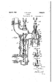
- Figure 1 is a longitudinal section taken substantially in theV plane of line 1 1 of Fig. 2 of an ej ector embodying the features of my invention.
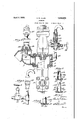
- Fig. 2 is a sectional side elevation of same.
- Fig. 3 shows a modiiied form of connections for the telltale alarm.
- Figs. 4, 5, 6, 7 and 8 show various modifications ⁇ of they checkvalve for the water inlet.
- n is a modiiied form of connections for the telltale alarm.
- Figs. 4, 5, 6, 7 and 8 show various modifications ⁇ of they checkvalve for the water inlet.
- the injector comprises 'ak body 1, having the usual injector tubes, designated .generally by 2, used in injectors of this type, and a water inlet opening 3 connected in anysuifable way, as by a flexible pipe or hose, (not shown), with the water supply tank on the locomotive tender.
- the body 1 is also provided with the steam inlet 4, connected by a pipe 5 with the steam space of the locomotive boiler and valve controlled, a water delivery opening @connected in the usual manner by means of a pipe and check-valve (not shown) with the locomotive boiler, and anoverilow 7 which is in communication wit-h the overflow chamber 8. f
- Thewater inlet-opening 3 is controlled by a valve having a seat 9 anda disk 10.V
- the disk 10 is provided with a sleeve 11 having holes 12 through which communication is afforded between the interior of the injector body and a heater port 13-in'v the disk.'y Into the sleeve 11, and slidable relatively thereto, extends the cylindrical end 14 of a valve stem 15 threaded at 16 into a bonnet 17 carried by the injector body. By means of the threaded engagement between the valve stem 15V and the bonnet 17 the valve stem may be moved relatively tov the :disk 10 so that the litt of the disk from itsvseat 9 may be limited to any desired height to control the amount of water admitted into the injector body.
- a plurality oi openings 12, arranged at various heights above the upper surface o'f the disk 10, provide means whereby any desired number of such openings may be opened or closed to thus vary the passage of heater steam through the port 13 as desired.
- the arrangement may be reversed, the openings 12b being formed in the hollow cylindrical portion 14a of the stem rather than in the sleeve 11.
- a plurality of openings such as the openings-12a of Fig.
- I may use a plurality of elongated slots 12, 'where by a similar result is obtained. Also, instead' of forming these elongated slots inthe sleeve 11, they maybe formed in the hollow portion Y 14a of the stem, as shown at 12, in Figs. if" and 8. Where the openings are formed in the hollow cylindrical portion of the stem, as in Figs. 6, 7 and 8, I may depend either upon the seating oi the bottom of the stein upon the seat 19 of the disk to close the heater port 13,' in which case, there must be a goed fit between the..
- the overflow 7 is controlled by acheck valvev 21 adapted to be held to its seat when desired by a stem 22 in screwthreaded engagement'as at 23 with a 'bonnet 24 supported by l" l the body 1 of the injector.
- This stem 22 may be provided with a universal joint connector 25 from which an operating rod or shaft maj.' run to the locomotive cab.
- valvestemv 15 is' provided with a uni# versal joint connector 26 and control rod similar to those used in connection with the valve stem 22.
- the overflow chamber 8 is provided with a cap 27 into which 1s fitted a conduit or pipe tural features as that shown in Fig'. 1, but omitting, of course, the steam valve.
- the combined telltale alarm and steam valve shown in Fig. 1 comprises a valve member 33, spring-loaded as shown at Se against a seat 35 and below this seat is arranged the steam valve 86 controlled by a stein 37 and hand wheel 38.
- injectors mounted in the usual position onwthe locomotive with the water inlet opening 3 connected by the usual flexible pipe or hose to the water tank on the locomotive tender, the steam inlet i connected to a valvecontrolled steam supply, the delivery 6 connected by a suitable pipe, check-valve-controlled, to the locomotive boiler, and the overflow 7 so arranged or connected as to have free discharge to atmosphere.
- the overflow check valve 21 is so adjusted that it may open to exhaust any pressure in overflow chamber 8 to atmosphere, but it will prevent entrance of air into the injector.
- Tn injectors of the type disclosed the valve 9-10 is used to regulate the supply of water feeding into the injector. Should the injector, when operating closed overflow,
- valve disk 10 will immediately seat, under the influence of the pressure developed within the injector body, and will prevent blowing off of the lleX- ible hose or pipe or blowing back into the tender tank. Under such circumstances the heater port 13 would be open but the elfect of this open port would be negligible so far as communication through it 0f pressure injurious to the water connection is concerned.
- the injector When the injector is not feeding water to' the locomotive boilerthe injector may be used as a heater, for heating the feed water, by admitting steam to the overflow chamber 8 from which Chamber it finds its way to the valve 9-10 and passing through the openings in the sleeve or stem thereof flows through the heater port 18 into the water in the flexible pipe or hose.
- the amount of steam passing thus into the feed water may be regulated by adjustment of the cylindrical portion le of the stern 15 in sleeve 11.
- This feature of valve 9-10 is particularly advantageous where a slight'opening of the main steam valve controlling communication with inlet l is used to supply heater steam to the injector.
- the amount of steam may be regulated by adjustment of valve 36 or 31, or by such valve in combination with the regulation aorded by valve 9--10. Should too much heater steam be supe plied, the telltale alarm will warn the engineer of this'fact.
- the disk 1() may be clamped against its seat 9 by vso depressing the stem 15 that the end of its cylindrical portion 14 seats against seat 19, or so that collar QOseats against the top of sleeve 11, thus not only preventing opening of the valve 9-10 but completely closing the heater port 13v as well.
- Such closing of valve 9-10 when there is no pressure in the injector body, will prevent water from entering the injector under the slight hydrostatic head maintained by the body of water in the tender tank.
- Vhat I claim is l.
- a body provided with an opening, an automatic check valve for said opening including a valve seat, a valve member for cooperation with said seat and provided vwith a port, and means for limiting movement of the valve member away from its seat and for positively seating same, said means operating to control the effective area of said port.
- an automatic check valve therefor including a valve seat, a valve member for cooperation with said seatand provided with a port, an adjustable valve stem, a guide member carried by said valve member and cooperating with said stem to guide said valve member relatively to saidA seat, said stem being operable to limit the movement of said valve member away from its seat and to positively seat same and to control the effective area of said port.
- an automatic check valve therefor including a valve seat, a valve disk for coopera-tion with said seat and provided with a port, a valve stem, guide sleeve carried by said disk and embracing said stem, said disk being ⁇ slidable toward and away from said seat relatively to said stem and guided on said stem by said sleeve, said stem operative to limit movement of said disk away from said seat and to positively seat same and to control. the effective area of said port.
- va body provided with a water supply opening
- an automatic check valve therefor including a valve seat, a valve disk for cooperation with said seat and provided with a port, a valve stem cooperating with said disk andadapted to limit the movement of said disk relatively to its seat and operable to positively seat same, and cooperating means on said stem and disk providing openings communicating with said port, said openings adapted to be controlled by movement of said stem relatively to said disk.
- an automatic check valve therefor including a valve seat, a valve disk forcooperation with said seat and provided with a port, a valve stem cooperating with said disk and adapted to limit the movement of said diskrelatively to its seat and operable to positively seat same, and cooperating means on said stem 'and' disk including a sleeve carried Vby said disk and in sliding engagement with said stem, said means providing openings communicating' with said port, said openings adapted to be controlled by movement of said stem relatively to said disk.
- an automatic check valve for controlling said opening including a valve seat and a disk cooperating therewith, said diskprovided with a port and a sleeve surrounding same, a valve stem insliding engagement with said .sleeve and axially adjustable in Said body to limit movement of said disk away from its seat and operable to positively seat same, said sleeve Vand stem forming cooperating valve members one of which'is provided with an aperture establishing communication between the interiorof said body and the port of said disk. adjust,- ment of said stem relatively to said disk servingto vary the effective area of said port by varying the area of said aperture.
- a. body provided with a water supply opening, an automatic check' valve for controlling ⁇ said opening including a valve seat and a disk cooperating' therewith, said disk provided with a port and a sleeve surroundingr same, a valve stem in sliding engagement with said sleeve and axially adjustable in saidV body to limit movement of said disk away from its seat and operable to positively seat same, said sleeve and stem forming cooperating valve members one of which is provided with means effecting an elongated aperture establishing communication between the interior of said body and the'portrof said disk, adjustment of said stem relatively to said disk serving to vary the effective area of said portl by varying the area ofsaid aperture.
- a body provided with a water inlet opening, a combined automatic check and manually operable valve for said opening including a seat and disk, said disk provided with a port, a sleeve projecting from said disk and surrounding said port, and valve stem provided with av portion cooperating with said sleeve and forming therewith a chamber in the sleevev to receive a body of water for balancing said disk when same is operating as a check valve, said stem operable to positively seat said disk.
- a body provided with a water inlet opening, a combined automatic check and manually operable valve for said opening including a seat and a disk, said disk provided with a port, a sleeve projecting from said disk and surrounding said port. and a valve stem provided with a hollow cylindrical portion cooperating with said sleeve and forming therewith a chamber to receive a body of Water for balancing said disk when same 1s operating as a check valve, said stem operable to positively seat said disk.
- an injector arbody provided with a water inlet opening, a combined automatic check and manually operable valve for said opening including a seat and a disk, said disk provided with a port, a valve stem cooperating with said disk and to which the disk is relatively movable for operation as a checkv valve, and means on said stem and disk-providing a chamber with which said port communicates, said chamber adapted to receive a body of water through said port to balance said disk when same is operating as a check valve, said stem operable to positively seat said disk.
- an injector provided with means for furnishing a heating fluid to the supply of water for the injector and an alarm device for signalling cessation of operation of the injector when in operating condition, a conduit apart fromthe injector and connecting said injector and alarm device, and a conduit leading from asource of heating fluid and connected with the conduit of said alarm device.
- an injector provided with means for furnishing a heating iuid to the supply of water for the injector and an alarm device for signalling cessation of operation of the injector when in operating condition, a conduit apart from the injector'and connecting said injector and alarm device, a conduit leading from a source of heating fluid and connected with the conduit of said alarm device, and a valve interposed in the conduit for the heating fluid for controlling the ad mission of suc-h fluid to the conduit of the alarm device.
- an injector for steam boilers a body provided with an overflow chamber, an alarm device located remotely from said injector, a conduit apart from said injector body and connecting said alarm device with said overflow chamberV and providingl a means whereby said alarm device may function when the injector ceases to operate while in' operating condition, means in said injector whereby a heating fluid may be supplied to the water fed to the injector, and a conduit connected with a source of heating fluid and communicating with the conduit of said alarm device for supplying heating fluid to said means.
- an injector for steam boilers a body provided with an overflow chamber, an alarm device located remotely from said injector, a conduit apart from said injector body and connecting said alarm device with said overiow chamber and providing a means whereby said alarm device may function when the injector ceases to operate while in operating condition, means in said injector whereby a heating fluid may be supplied to the water fed to the injector, a conduit connected with a source of heating fluid and communicating with the conduit of said alarm device, and a valve interposed in said heating fluid conduit for controlling the passage of fluid therefrom into the alarm device conduit, whereby a single conduit may serve to supply heating fluid to said injector and to conduct uid under pressure from the injector to said alarm device.
- a body provided with a water inlet opening, a .combined check and manually operable valve for said opening including a seat, a valve disk vfor cooperation with said seat, and adjustable means for varying the effective opening of saidvalve when same is operating as a check valve, and to positively seat said disk, to thereby automatically and manually control the feed of water to the injector.
Landscapes
- Engineering & Computer Science (AREA)
- Physics & Mathematics (AREA)
- Fluid Mechanics (AREA)
- Mechanical Engineering (AREA)
- General Engineering & Computer Science (AREA)
- Nozzles (AREA)
Description
C. B. ALLEN ,April s, 1932.
INJECTOR Filed June 15, 1929 2 sheds-sheet lIl .2 sneetseet 2 amm c- B- ALLEN INJECTOR Filed June l5, 1929 April 5, 1932.
Patented Apr. 5, 1932 Urrea STATES PATENT- Arr j CHARLES B. ALLEN, OF WADSWORTH, OHO, ASS'IGIil'O-ltV TO THE' `Oli-10 INJECTOR Y v COMPANY, OF WADSWORTH, OHIO, A CORPORATION 'OF OIE-EIOl imiteren Application` filed June l5,
This invention relates to injectors for feeding water to locomotive boilers. l
In one type of injectors, of which that shown in the drawings, hereinafter dev scribed, is an example, the water inlet of the injector, which is connected to the water tank of the locomotive tender b-y a `flexible pipe or hose, is controlled by a valve which may be manually adjusted toward and away from its seat to regulate the supply of water to the injector, and which may be positively seated. l Y When back pressure occurs in the injector, due to various known causes, the communica- .15. tion of such pressure to thel water inletis apt to result in blowing olf of the Ihose and breaking of the connection between the `in j ector and the tender tank when a manually operated inlet valve is used, and therefore in some other injectors, particularly those Ain which regulation of the steamsupply is de pended upon for regulating the volume'of water fed by the injector, a check valvegis placed in the water inlet, and 'this valve is provided with a port which, when the valve is closed, and the injector not operating, will permit steam fed to the injector'body to 'pass back into the hose connection to heat the water. This check valve will automatically seat upon occurrence of back pressure in the injector body. I As is nwellknown, 'the 'delivery connection, which delivers the water from the injector tothe locomotive boiler, is provided with a check valve to prevent feed back from the boiler into the injector, and if this valve should stick, thus opening the injector to boiler pressure, the check valve used in the water inlet will seat under such pressure, preventing blowing back into the tender 40 tank. j
It will be seen that both forms of valve have their advantages and disadvantages. The manually operated valve has the advantage of positive control of the feed but will not automatically prevent blowing back into the tank. and the check valve will automatif cally prevent blowing back but will not control the feed.
One object of my invention is vto provide a valve for the water inlet of injectors which leze. .serial no. 371,277.Y
combines the advantages ofthe manually operable valveand the'check valve just V4:described, this valve being in theform 'of a check valve having means whereby it may be adjusted relatively to its seat vvand pro-vided with a port through which heater steam may be introduced into the feed water, the valve and its arrangement being such that theeffective area of this port may be controlled, the lift of the lvalve disk from its seat regulated to control the feed and the valve positively seated to completely close the water inlet and the port yin the valve when desired.l
In injectors of the type hereinbefore mentioned in which lheater stearn so called, is used, this steam is in some instances supplied to the injector body by permitting the` main steam valve of the injector to remain part'ially open. Sometimes, however, a special conduit is run from the locomotive boiler to the injector body to furnish aseparate supply of such steam, this 'conduit usually'being in the form of va small pipe-line con-Y troglled by ra valve located in the locomotive ca Furthermore, itis customary to provide inj ectors with what is known as a telltale alarm, which isI usuallyin' the form of a springQloaded check valve located in orl adjacent to the locomotive cab and connected by a conduit or pipe line' with the body of the injector. TThis telltale alarm 'operates automatically upon occurrence lof high pressure within the body of the injector caused by acessation of operation or breaking of the injector when it is iii-operating condition, that is, when its steam supply is turned on.
It will be seen that where the separate heat-i er steam supply and the telltale alarm are both used, there are two steam lines or conduits running from the injector to the locomo tive cab; and a further object of my invention is' to 'so combine the separate heater steam connection and the telltale alarm valve as to eliminate one of such lines.
-From the foregoing,` it will be seen `that my rinvention contemplates a water inlet v valve, preferably of` check-valve type, ,proj vided with a heater portandwith means for so operating the valve thatsame may be adalso the combination with a telltale alarm or".
means for supplying heater steam to the injector body, as I will proceed now to explain and finally claim. l
In the accompanying drawings illustrating the invention, in the several figures of which like parts aresimilarly designated, Figure 1 is a longitudinal section taken substantially in theV plane of line 1 1 of Fig. 2 of an ej ector embodying the features of my invention. Fig. 2 is a sectional side elevation of same. Fig. 3 shows a modiiied form of connections for the telltale alarm. Figs. 4, 5, 6, 7 and 8 show various modifications `of they checkvalve for the water inlet. n
The injector comprises 'ak body 1, having the usual injector tubes, designated .generally by 2, used in injectors of this type, and a water inlet opening 3 connected in anysuifable way, as by a flexible pipe or hose, (not shown), with the water supply tank on the locomotive tender. The body 1 is also provided with the steam inlet 4, connected by a pipe 5 with the steam space of the locomotive boiler and valve controlled, a water delivery opening @connected in the usual manner by means of a pipe and check-valve (not shown) with the locomotive boiler, and anoverilow 7 which is in communication wit-h the overflow chamber 8. f
Thewater inlet-opening 3 is controlled by a valve having a seat 9 anda disk 10.V The disk 10 is provided with a sleeve 11 having holes 12 through which communication is afforded between the interior of the injector body and a heater port 13-in'v the disk.'y Into the sleeve 11, and slidable relatively thereto, extends the cylindrical end 14 of a valve stem 15 threaded at 16 into a bonnet 17 carried by the injector body. By means of the threaded engagement between the valve stem 15V and the bonnet 17 the valve stem may be moved relatively tov the :disk 10 so that the litt of the disk from itsvseat 9 may be limited to any desired height to control the amount of water admitted into the injector body. Obviously, when the end 18 of the cylindrical portion 14 of the valve stem is screwed down tight against a seat 19 surrounding the heater port 13 the disk`10 will be held iixedly against its seat 9 and the supply of water to the injector completely cut oli. Moreover, when this condition exists, it will be apparent that the communication through the openings 12 between the injector body and the heater port 13 will also be completely closed. Any adjustment of the valve stem 15, and hence of the cylindrical portion 14 thereof, may be had to control the eective area of the heater port 13 by more or less obstructing the openings 12, as desired.
The manner of control of the heater port 13 will be particularly apparent when the valve disk and the cylindrical portion of the stem take the modified forms shown in Figs. 4 to 8 inclusive. In Fig. 4, a plurality oi openings 12, arranged at various heights above the upper surface o'f the disk 10, provide means whereby any desired number of such openings may be opened or closed to thus vary the passage of heater steam through the port 13 as desired. As shown in Figl, the arrangement may be reversed, the openings 12b being formed in the hollow cylindrical portion 14a of the stem rather than in the sleeve 11. As illustrated in Fig. 5, instead of using a plurality of openings, such as the openings-12a of Fig. 4, arranged'at various distances above the vtop of the disk 1.0, I may use a plurality of elongated slots 12, 'where by a similar result is obtained. Also, instead' of forming these elongated slots inthe sleeve 11, they maybe formed in the hollow portion Y 14a of the stem, as shown at 12, in Figs. if" and 8. Where the openings are formed in the hollow cylindrical portion of the stem, as in Figs. 6, 7 and 8, I may depend either upon the seating oi the bottom of the stein upon the seat 19 of the disk to close the heater port 13,' in which case, there must be a goed fit between the.. inner surface of the sleeve 11 and the outer surface of the cylindrical end of the stem, or I may provide the-stem with a collar 20 adapted to seat upon the upper en d. of the sleeve 11, as shown in 8. It will be apparent that the arrangement of the openings 12a .(Fig. 4), 12b (Fig. 6) and the slots 12c and 12@y Figs. 5, 7 and 8 respectivelyl provides means effecting elongated apertures which, whenY the stem portion 14 or 14L 1s moved vrelatively to them have 'their areas so varied as to vary the effective area of heater port 13. V
The overflow 7 is controlled by acheck valvev 21 adapted to be held to its seat when desired by a stem 22 in screwthreaded engagement'as at 23 with a 'bonnet 24 supported by l" l the body 1 of the injector. This stem 22 may be provided with a universal joint connector 25 from which an operating rod or shaft maj.' run to the locomotive cab.
The valvestemv 15 is' provided with a uni# versal joint connector 26 and control rod similar to those used in connection with the valve stem 22.
The overflow chamber 8 is provided with a cap 27 into which 1s fitted a conduit or pipe tural features as that shown in Fig'. 1, but omitting, of course, the steam valve.
The combined telltale alarm and steam valve shown in Fig. 1 comprises a valve member 33, spring-loaded as shown at Se against a seat 35 and below this seat is arranged the steam valve 86 controlled by a stein 37 and hand wheel 38.
By thus connecting the telltale alarm and the heater steam supply valve, whether the arrangement shown in Fig. 2 or in Fig. 3 is used, with a single pipe 28 leading to the overllow chamber 8, l dispense with one pipe line from injector to locomotive cab, as hereinbefore mentioned, thus simplifying instal lation and reducing cost of the apparatus without impairing its efficiency. Y Y
The operation of injectors provided with the improvements of my invention will, it is believed, be obvious to those skilled in thev art, but in the interest of clearness it be described briefly as follows The injectoris mounted in the usual position onwthe locomotive with the water inlet opening 3 connected by the usual flexible pipe or hose to the water tank on the locomotive tender, the steam inlet i connected to a valvecontrolled steam supply, the delivery 6 connected by a suitable pipe, check-valve-controlled, to the locomotive boiler, and the overflow 7 so arranged or connected as to have free discharge to atmosphere. rThe overflow check valve 21 is so adjusted that it may open to exhaust any pressure in overflow chamber 8 to atmosphere, but it will prevent entrance of air into the injector. N hen the injector is operating normally there is a partial vacuum in the overflow chamber, but if the mixture of water and steam passing through the injector tubes 2 rises above a predetermined temperature, whichv rise may be due to in- (lll creased steam pressure, increased temperature of feed, reduction in quantity of water supply,vor a combination of these factors, water will issue from the spills of the tubes, raise check valve Q1 and issue from the overflow opening. This is the limit of open overflow operation. lf, now, the check valve 21 is clamped to its seat by stem 22 the water cannot escape from the overflow and the injector will continue to function even though the conditions (increased temperature &c.) which interfere with operation become more severe. When, however, a certain critical temperature or condition is reached, the injector will cease to function or break. This is the limit of closed overflow operation. Vhen this occurs the telltale alarm will operate to apprise the engineer of the fact that the injector has ceased functioning. v
Tn injectors of the type disclosed the valve 9-10 is used to regulate the supply of water feeding into the injector. Should the injector, when operating closed overflow,
break, as just described, the valve disk 10 will immediately seat, under the influence of the pressure developed within the injector body, and will prevent blowing off of the lleX- ible hose or pipe or blowing back into the tender tank. Under such circumstances the heater port 13 would be open but the elfect of this open port would be negligible so far as communication through it 0f pressure injurious to the water connection is concerned.
When the injector is not feeding water to' the locomotive boilerthe injector may be used as a heater, for heating the feed water, by admitting steam to the overflow chamber 8 from which Chamber it finds its way to the valve 9-10 and passing through the openings in the sleeve or stem thereof flows through the heater port 18 into the water in the flexible pipe or hose. The amount of steam passing thus into the feed water may be regulated by adjustment of the cylindrical portion le of the stern 15 in sleeve 11. This feature of valve 9-10 is particularly advantageous where a slight'opening of the main steam valve controlling communication with inlet l is used to supply heater steam to the injector. Where a separate heater steam vsupply, such as pipe 28, is used, the amount of steam may be regulated by adjustment of valve 36 or 31, or by such valve in combination with the regulation aorded by valve 9--10. Should too much heater steam be supe plied, the telltale alarm will warn the engineer of this'fact. z i
Obviously, if desired, the disk 1() may be clamped against its seat 9 by vso depressing the stem 15 that the end of its cylindrical portion 14 seats against seat 19, or so that collar QOseats against the top of sleeve 11, thus not only preventing opening of the valve 9-10 but completely closing the heater port 13v as well. Such closing of valve 9-10, when there is no pressure in the injector body, will prevent water from entering the injector under the slight hydrostatic head maintained by the body of water in the tender tank.
It is to be noted, moreover, that by forming the end of stem 15 as a hollow cylinder 14, the water which fills the space defined Vby the hollow cylinder 14C and sleeve 11, will balance the valve when water is being fed through same to the injector. This water will not, however, interfere with proper adjustment of the valve, for the reason that it may esca-pe from the space within cylinder 14 and sleeve 11 as readily as-it enters same. The effect is primarily a balancing of the pressures upon the two sides of the valve during normal operation.
Although I have hereinbefore described my invention in its application to the boilers of locomotives, it is to be understoodthatitis not limited to this particular application but may be used in connection with any boiler so long Anio as the requisite pressure liuid, such as steam, and a supply of water are available.
Various changes are contemplated as within the spirit of the invention and the scope of the following claims.
Vhat I claim is l. In an injector, a body provided with an opening, an automatic check valve for said opening including a valve seat, a valve member for cooperation with said seat and provided vwith a port, and means for limiting movement of the valve member away from its seat and for positively seating same, said means operating to control the effective area of said port.
2. In an injector, a body provided with an opening, an automatic check valve therefor including a valve seat, a valve member for cooperation with said seatand provided with a port, an adjustable valve stem, a guide member carried by said valve member and cooperating with said stem to guide said valve member relatively to saidA seat, said stem being operable to limit the movement of said valve member away from its seat and to positively seat same and to control the effective area of said port. 3. In an injector, a body provided with a Water supply opening, an automatic check valve therefor including a valve seat, a valve disk for coopera-tion with said seat and provided with a port, a valve stem, guide sleeve carried by said disk and embracing said stem, said disk being` slidable toward and away from said seat relatively to said stem and guided on said stem by said sleeve, said stem operative to limit movement of said disk away from said seat and to positively seat same and to control. the effective area of said port.
4. In an injector, va body provided with a water supply opening, an automatic check valve therefor including a valve seat, a valve disk for cooperation with said seat and provided with a port, a valve stem cooperating with said disk andadapted to limit the movement of said disk relatively to its seat and operable to positively seat same, and cooperating means on said stem and disk providing openings communicating with said port, said openings adapted to be controlled by movement of said stem relatively to said disk.
5. -In anv injector, a body-provided with a water supply opening, an automatic check valve therefor including a valve seat, a valve disk forcooperation with said seat and provided with a port, a valve stem cooperating with said disk and adapted to limit the movement of said diskrelatively to its seat and operable to positively seat same, and cooperating means on said stem 'and' disk including a sleeve carried Vby said disk and in sliding engagement with said stem, said means providing openings communicating' with said port, said openings adapted to be controlled by movement of said stem relatively to said disk. f
6. In an injector, la body provided with a water supply opening, an automatic check valve for controlling said opening including a valve seat and a disk cooperating therewith, said diskprovided with a port and a sleeve surrounding same, a valve stem insliding engagement with said .sleeve and axially adjustable in Said body to limit movement of said disk away from its seat and operable to positively seat same, said sleeve Vand stem forming cooperating valve members one of which'is provided with an aperture establishing communication between the interiorof said body and the port of said disk. adjust,- ment of said stem relatively to said disk servingto vary the effective area of said port by varying the area of said aperture.
7. In an injector, a. body provided with a water supply opening, an automatic check' valve for controlling` said opening including a valve seat and a disk cooperating' therewith, said disk provided with a port and a sleeve surroundingr same, a valve stem in sliding engagement with said sleeve and axially adjustable in saidV body to limit movement of said disk away from its seat and operable to positively seat same, said sleeve and stem forming cooperating valve members one of which is provided with means effecting an elongated aperture establishing communication between the interior of said body and the'portrof said disk, adjustment of said stem relatively to said disk serving to vary the effective area of said portl by varying the area ofsaid aperture.
8.' In an injector, a body provided with a water inlet opening, a combined automatic check and manually operable valve for said opening including a seat and disk, said disk provided with a port, a sleeve projecting from said disk and surrounding said port, and valve stem provided with av portion cooperating with said sleeve and forming therewith a chamber in the sleevev to receive a body of water for balancing said disk when same is operating as a check valve, said stem operable to positively seat said disk. l
9. In an injector, a body provided with a water inlet opening, a combined automatic check and manually operable valve for said opening including a seat and a disk, said disk provided with a port, a sleeve projecting from said disk and surrounding said port. and a valve stem provided with a hollow cylindrical portion cooperating with said sleeve and forming therewith a chamber to receive a body of Water for balancing said disk when same 1s operating as a check valve, said stem operable to positively seat said disk.
l0. I n an injector, arbody provided with a water inlet opening, a combined automatic check and manually operable valve for said opening including a seat and a disk, said disk provided with a port, a valve stem cooperating with said disk and to which the disk is relatively movable for operation as a checkv valve, and means on said stem and disk-providing a chamber with which said port communicates, said chamber adapted to receive a body of water through said port to balance said disk when same is operating as a check valve, said stem operable to positively seat said disk.
11. In an injector provided with means for furnishing a heating fluid to the supply of water for the injector and an alarm device for signalling cessation of operation of the injector when in operating condition, a conduit apart fromthe injector and connecting said injector and alarm device, and a conduit leading from asource of heating fluid and connected with the conduit of said alarm device.
12. In an injector provided with means for furnishing a heating iuid to the supply of water for the injector and an alarm device for signalling cessation of operation of the injector when in operating condition, a conduit apart from the injector'and connecting said injector and alarm device, a conduit leading from a source of heating fluid and connected with the conduit of said alarm device, and a valve interposed in the conduit for the heating fluid for controlling the ad mission of suc-h fluid to the conduit of the alarm device.
13. In an injector for steam boilers, a body provided with an overflow chamber, an alarm device located remotely from said injector, a conduit apart from said injector body and connecting said alarm device with said overflow chamberV and providingl a means whereby said alarm device may function when the injector ceases to operate while in' operating condition, means in said injector whereby a heating fluid may be supplied to the water fed to the injector, and a conduit connected with a source of heating fluid and communicating with the conduit of said alarm device for supplying heating fluid to said means.
111. In an injector for steam boilers, a body provided with an overflow chamber, an alarm device located remotely from said injector, a conduit apart from said injector body and connecting said alarm device with said overiow chamber and providing a means whereby said alarm device may function when the injector ceases to operate while in operating condition, means in said injector whereby a heating fluid may be supplied to the water fed to the injector, a conduit connected with a source of heating fluid and communicating with the conduit of said alarm device, and a valve interposed in said heating fluid conduit for controlling the passage of fluid therefrom into the alarm device conduit, whereby a single conduit may serve to supply heating fluid to said injector and to conduct uid under pressure from the injector to said alarm device.
15. In an injector, a body provided with a water inlet opening, a .combined check and manually operable valve for said opening including a seat, a valve disk vfor cooperation with said seat, and adjustable means for varying the effective opening of saidvalve when same is operating as a check valve, and to positively seat said disk, to thereby automatically and manually control the feed of water to the injector. Y v
In testimony whereof I have hereunto set my hand this 7th day of June A. D. 1929.
CHARLES B. ALLEN.
Priority Applications (1)
| Application Number | Priority Date | Filing Date | Title |
|---|---|---|---|
| US37127729 US1852070A (en) | 1929-06-15 | 1929-06-15 | Injector |
Applications Claiming Priority (1)
| Application Number | Priority Date | Filing Date | Title |
|---|---|---|---|
| US37127729 US1852070A (en) | 1929-06-15 | 1929-06-15 | Injector |
Publications (1)
| Publication Number | Publication Date |
|---|---|
| US1852070A true US1852070A (en) | 1932-04-05 |
Family
ID=23463287
Family Applications (1)
| Application Number | Title | Priority Date | Filing Date |
|---|---|---|---|
| US37127729 Expired - Lifetime US1852070A (en) | 1929-06-15 | 1929-06-15 | Injector |
Country Status (1)
| Country | Link |
|---|---|
| US (1) | US1852070A (en) |
-
1929
- 1929-06-15 US US37127729 patent/US1852070A/en not_active Expired - Lifetime
Similar Documents
| Publication | Publication Date | Title |
|---|---|---|
| US1852070A (en) | Injector | |
| US1231280A (en) | Safety-valve. | |
| US2046887A (en) | Injector | |
| US1560829A (en) | Safety valve | |
| US247464A (en) | John loftus | |
| US1579526A (en) | Feed-control apparatus for steam boilers | |
| US784067A (en) | Valve-fitting. | |
| US660690A (en) | Boiler attachment. | |
| US1092570A (en) | Multiple-circuit steam-heating system. | |
| US1541321A (en) | Exhaust-steam injector | |
| US892515A (en) | Safety-valve for car-heating appliances. | |
| US1902969A (en) | Feed water heater for locomotives | |
| US770635A (en) | Feed-water regulator | |
| US302543A (en) | Henry p | |
| US1449228A (en) | Locomotive boiler | |
| US2032674A (en) | High pressure injector | |
| US495336A (en) | Injector | |
| US1787432A (en) | Operating mechanism for injectors | |
| US1706346A (en) | Steam injector | |
| US1984547A (en) | Exhaust steam injector | |
| US2091939A (en) | Device for controlling the discharge of gaseous fluids or material | |
| US726123A (en) | Automatic water-feed regulator for steam-boilers. | |
| US757849A (en) | Injector for steam-boilers. | |
| US499074A (en) | Water-supplying device for locomotive-tenders | |
| US1038826A (en) | Injector. |