US1852053A - Depository - Google Patents
Depository Download PDFInfo
- Publication number
- US1852053A US1852053A US572346A US57234631A US1852053A US 1852053 A US1852053 A US 1852053A US 572346 A US572346 A US 572346A US 57234631 A US57234631 A US 57234631A US 1852053 A US1852053 A US 1852053A
- Authority
- US
- United States
- Prior art keywords
- door
- opening
- spindle
- carrier
- plate
- Prior art date
- Legal status (The legal status is an assumption and is not a legal conclusion. Google has not performed a legal analysis and makes no representation as to the accuracy of the status listed.)
- Expired - Lifetime
Links
- 208000027418 Wounds and injury Diseases 0.000 description 3
- 230000006378 damage Effects 0.000 description 3
- 208000014674 injury Diseases 0.000 description 3
- 238000010276 construction Methods 0.000 description 2
- 239000000126 substance Substances 0.000 description 2
- 241000251468 Actinopterygii Species 0.000 description 1
- 210000000078 claw Anatomy 0.000 description 1
- 230000000295 complement effect Effects 0.000 description 1
- 238000006073 displacement reaction Methods 0.000 description 1
- 238000003780 insertion Methods 0.000 description 1
- 230000037431 insertion Effects 0.000 description 1
- 238000000034 method Methods 0.000 description 1
- 230000001681 protective effect Effects 0.000 description 1
- 238000010008 shearing Methods 0.000 description 1
- 238000003466 welding Methods 0.000 description 1
Images
Classifications
-
- E—FIXED CONSTRUCTIONS
- E05—LOCKS; KEYS; WINDOW OR DOOR FITTINGS; SAFES
- E05G—SAFES OR STRONG-ROOMS FOR VALUABLES; BANK PROTECTION DEVICES; SAFETY TRANSACTION PARTITIONS
- E05G1/00—Safes or strong-rooms for valuables
Definitions
- This invention relates to a depository such as may be used for the safekeeping of money or valuables deposited therein from time to time and from which the articles so deposited cannot be removed, except by the use of one or more keys or other means of unlocking the device.
- An object of the invention is to provide a depository with novel means for precluding unauthorized removal of the contents thereof by means of hooked wires or other devices designed to remove the contents.
- Another object is to provide a device of the character above stated, wherein no sharp 5 pointed claws are employed for resisting removal of the contents of the depository, thereby saving frominjury the hand and the clothing of a person authorized to reach into the depository and remove the contents after unlocking of the device.
- Another object is to provide a depository having a rotatable door structure including a novel arrangement of lock, handle spindle, and guard plate, whereby a maximum of safety is afforded the contents of the depository and the entry of dirt and other foreign substances is precluded.
- Fig. 1 is a longitudinal cross sectional view of the device of the invention, in locked condition.
- Fig. 2 is an elevational View showing in detail a handle-spindle forming part of the invention.
- Fig. 3 is a plan view taken on line 33 of Fig. 2.
- Fig. 1 is a bottom plan view of a movable carrier plate forming a detail of the invention.
- Fig. 5 is a cross sectional view taken on line 55 of Fig. 1.
- Fig. 6 is a cross sectional view taken on line 66 of Fig. 1.
- Fig. 7 is a cross sectional view similar to Fig. 1, showing the device in the unlocked condition.
- the device of this invention comprises a receptacle 8 adapted to be partially buried in a concrete block, or suitably secured to some other firm support, and provided at its upper end with an opening 9'for reception of a rotatable door 10.
- the body of the receptacle is provided with a series of longitudinal arcuate lugs 12, beneath which lugs the complementary similar lugs 13 of the door may be disposed, upon rotating the door, to preclude lifting of the door from the opening 9. While the lugs are disposed in the operative position above described, the locking bolt 14 of the door mav be caused to enter arecess 15 in the wall of opening 9 for the purpose of precluding rotational movement of the door by means of the handle-spindle indicated at 16.
- the door body 10 is provided with an opening 17 for reception of the normally rotatable handlespindle 16 which carries the fixed plate-like elements 18 and 19 both of which are adapted to rotate with the handle-spindle.
- the elements 18 and'19 hereafter will be referred to as the guard plate and the movable carrier support respectively. 2
- the guard plate 18, door 10, and the carrier support 19, are provided with deposit receivslots or openings 20, 21 and 22, respectively, which slots or openings may be caused to register with one another by manually rotating the handle-spindle 16 to the position shown in Fig. 1.
- Articles inserted into the opening 20 thereby may be caused to drop through the openings 21 and 22 and into the horn shaped or tubular carrier 23.
- the articles thus disposed within the tubular carrier will rest upon a smooth surfaced division plate 24, which plate has an opening or slot 25 remote from the normal position of 1, the carrier 23 and with which the carrier may be placed in registration by actuating the handle-spindle.
- the carrier 23 By rotating the carrier support 19 to a proper position, the carrier 23 will register with the opening 25 and the 18 and 19 may be rotated for disengagement of the lugs 12 and 13, as hereinbefore described, and lifted bodily from the receptacle. Thereafter, the division plate 24 may be lifted from its position on the annular shoulder 28 and removed bodily from the receptacle, thereby affording free and unrestricted access to the compartment 26.
- the division plate may be precluded from rotational movement within the receptacle by means of a stud 29 received in a slotor opening 80 of the plate; the plate is not necessarily secured to the receptacle 8.
- the guard plate 18 and the carrier support 19 may be caused to rotate with the spindle by providing flat portions 31 and 32 on the spindle adapted for reception in the angular perforations 33 and 34, respectively, of the members 18 and 19.
- This connection could be made by a welding or shrinking process, or by means of any suitable securing devices such as pins or screws.
- a nut 35 or its equivalent may engage the lower end of the spindle for maintaining the plate 19 in position thereon.
- the edges of said opening normally are not parallel with those of the tubular carrier, but are disposed at an angle thereto so that rotation of the tubular carrier through an are exceeding 180 degrees is required for effecting registration of the tubular carrier with the opening 25.
- a suitable stationary stop 36 serves to limit rotational movement of the carrier tube and said stop may be carried by any stationary part of the rdevice, such asplate 24.
- the stop preferably is so located as to permit rotation of the carrier tube farther than the registry position with the opening 25, the purpose of such stop location being to confuse one who is not familiar with theconstruction of the device, and thereby preclude determination of the locationof the opening 25.
- the stop 86 may also limit backward rotation of the elements 18 and 19. r
- the door 10 is provided with a suitable lock 27 that may be actuated by means of one or more keys.
- Thekey receptacles of the lock are indicated at 37, and they are so arranged in the door 10 that rotational movement of the guard plate 18 may cause the opening 20 thereof to register with the key receptacles, (Fig. 7), thereby possible the insertion of a key or keys.
- the guard plate also serves a protective cover for the door jamb, which the cover overhangs.
- the door f may comprise a number of plate members secured together by the screws 38.
- a durable and effective door bolting mechanism is provided.
- the bolt 14 comprovide a passage through which the dog may bemoved for retraction of the bolt 14 after release thereof by unlocking of the lock means 27.
- the bolt has extendingtherefrom a lock bar 41 that enters the lock and normally is held thereby. It will readily be apparent from the disclosure of Fig. 6, that an attempt to force the bolt 14 from the recess 15 results in engagement of the dog 39 with a spindle 16, which precludes injury to the lock 27. It
- bolt 14 may, by
- the locking bolt 14 may be provided with a suitable guide 42 adapted to enter and slide within a guide way 43 formed in the door 10.
- the guard plate may be moved, by means ofthe handle-spindle, to cause registration of the three'openings 20, 21 and 22. he article to be deposited may thereupon be dropped into the carrier tube 28, after which the guard plate may be ro- L ill.-
- the dog 39 being then in contact with the face 4:0 affords a locked relationship between the spindle and the door, whereby the spindle may be employed for bodily rotating the door and lifting it from its normal'position on the safe or depository.
- the collector may reach into the depository and remove the plate 24:, thereby exposing the contents of the depository.
- a depository comprising in combination a receptacle having a door opening, a bodily removable rotatable door for closing the opening, said door having a deposit receiving opening therein, cooperative door securing means associated with the door and the re ceptacle and adapted to engage and disengage upon rotation of the door, a bolt and a locking mechanism associated therewith for locking the door against rotational movement, a handle-spindle normally rotatable relative to the door, a carrier plate and a guard plate each fixed for movement with the handlespindle and each having an opening therein adapted to register with the deposit receiving opening of the door when the handle spindle is rotated, a division plate in the receptacle having an opening out of alignment with the opening of the door, a guide for deposited articles said guide being movable with the carrier plate and adapted to carry deposited articles to the opening of the division plate when the handle-spindle is rotated, and means associated with the locking mechanism for fixing the handlespindle against rotation relative the door whereby to
- a depository comprising in combination a receptacle having a door opening, a non mally stationary door for closing the open ing and having a deposit receiving opening therein, a handle-spindle normally rotatable relative to the door and extending therethrough, a carrier support fixed upon the innor end of the handle-spindle and having an opening therein adapted to register With the deposit receiving opening of the door, a perforated division plate supported in the receptacle intermediate its top and bottom, the
- perforation of the division plate being disposed in a non-registering position relative to the deposit receiving opening of the door, and a carrier for deposited articles the carrier being movable with the carrier support and adapted to move deposited articles relative the division plate until said articles drop through the perforation of the division plate and into the space below it.
- a depository comprising in combination a receptacle having a door opening, a normally stationary door for closing the opening and having a deposit receiving opening therein, a handle-spindle normally rotatable relative to the door and extending therethrough, a carrier support fixed upon the inner end of the handle-spindle and having an opening therein adapted to register with the deposit receiving opening of the door, a perforated division plate supported in the receptacle intermediate its top and bottom, the perforation of the division plate being disposed in a nonregistering position relative to the deposit receiving opening of the door, a carrier for a receptacle having a door opening, a normal- 1y stationary door forclosing the opening and having a deposit receiving opening therein, a handle-spindle normally rotatable relative to the door and extending therethrough, a carrier support fixed upon the inner end of the handle-spindle and having an opening therein adapted to register with the deposit receiving opening of the door, a per fora-ted division
- a carrier for deposited articles the carrier be-v ing movable with the carrier support and adapted to move deposited articles relative the division plate until said articles drop through the perforation of the division plate and into the space below it, and a guard plate disposed exteriorly of and overhanging the edges of the door and arranged for movement with the spindle and the carrier said guard plate having a perforation therein coinciding with the opening of the carrier sup port and movable to a position in coinciding relationship with the deposit receiving opening of the door.
- a depository comprising in combination a receptacle having a door opening, a normally stationary 'door for closing the opening and having a deposit receiving opening therein aliaiidle-spindle normally rotatable relative to the door and extending therethrough, a carrier support fixed upon the inner end of the handle-spindle and having an opening therein adapted to register with the deposit receiving opening of the door, a perforated division plate supported in the receptacle intermediate its top and bottom, the perforation of the division plate being disposed in a non-registering position relative to the deposit receiving opening of the door, a carrier for deposited articles the carrier being movable with the carrier support and adapted to move deposited articles relative the division plate until said articles drop through the perforation of the division plate and into the space below it and a stop for limiting rotational movement of the carrier.
- a depository comprising in combination a receptacle having a door opening, a normally stationary door for closing the opening and having a deposit receiving opening therein, a handle-spindle normally ro-c tatable relative to the door and extending therethrough, a carrier support fixed upon the inner end of the handle-spindle and having an opening therein adapted to register withthe deposit receiving opening of the door, a perforated division plate supported in the receptacle intermediate its top and bottom, the perforation of the divison plate being disposed in a non-registering position relative to the deposit receiving opening of the door, a carrier for deposited articles the carrier being movable with the carrier support and adapted to move deposited articles relative the division.
- guard plate disposed exteriorly of the door and ar ranged for movement with the spindle and the carrier said guard plate having a perforation therein coinciding with the opening of the carrier support and movable to a position in coinciding relationship with the deposit receiving opening of the door and a ,door lock covered normally by the guard plate but positioned so as to beexposed through the perforation of the guard plate when the guard plate is moved from coinciding relationship with the deposit receiving opening of the door.
- a depository comprising in combination a receptacle having a door opening, a
- bodily removable rotatable door for closing the opening said door having a deposit-receiving opening therein, cooperative door securing means associated with the door and the receptacle and adapted to engage and disengage upon rotation of the door, a bolt and a locking mechanism associated therewith for locking the door against rotational movement, a handle-spindle normally rotatable relative to the door, a member fixed for move DC opening therein, cooperative door securing means associated with the door and the receptacle and adapted to engage and disengage upon rotation of the door, a bolt and a locking mechanism associated therewith for locking the door against rotational movement, a handle-spindle normally rotatable relative to the door, a member fixed for movement with the handle-spindle and havingan opening therein adapted to register with the opening of the door when the hanrile-spindle is rotated and means associated with the locking mechanism for fixing the handle-spindle against rotation relative the door whereby to render the handle-spindle operable for
- a door for depositories and the like comprising in combination a body portion opening said door having a deposit-receiving .ll
- a deposit receiving opening therein having a deposit receiving opening therein, a rotatable spindle extending through the body portion of the door, a guard plate adj a cent one face of the door and overhanging the edges of the door and having a perforation therein adapted to be placed in registration with the deposit receiving opening of the door body, means for fixing the guard plate relative to the rotatable spindle, and a carrier fixed relative to the spindle and disposed adjacent another face of the door, said carrier having an opening therein coinciding with the opening of the guard plate and movable with the spindle to a position in registration with the deposit receiving opening of the door body.
- a door for depositories and the like comprising in combination a body portion having a deposit receiving opening therein, a rotatable spindle extending through the body portion of the door, a guard plate adjacent one face of the door and overhanging the edges of the door and having a perforation therein adapted to be placed in registration with the deposit receiving opening of the door body, means for fixing the guard plate relative to the rotatable spindle, and a carrier fixed relative to the spindle and di posed adjacent another face of the door, said carrier having an opening therein coinciding with the opening of the guard plate and movable with the spindle to a position in registration with the deposit receiving opening of the door body and a door lock normally covered by the guard plate but rendered accessible through the guard plate perforation upon rotation of the spindle.
- a door for depositories and the like comprising in combination a body portion having a deposit receiving opening therein, a rotatable spindle extending through the body portion of the door, a guard plate adjacent one face of the door overhanging the edges of the door and having a perforation therein adapted to be placed in registration with the deposit receiving opening of the door body, means for fixing the guard plate relative to the rotatable spindle, and a carrier fixed relative to the spindle and disposed adjacent another face of the door, said'carrier having an opening therein coinciding with the opening of the guard plate and movable with the spindle to a position in registration with the deposit receiving opening of the door body.
- a door for depositories and the like comprising in combination a body portion, a normally rotatable handle-spindle extending through the body portion, a lock supported by the door, a lock bolt slidably mounted relative the door and having a portion normally extending beyond the door for reception in a keeper, a dog on the lock bolt adapts ed to substantially abut the spindle while the bolt is extended so as to preclude forcible retraction of the bolt and injury to the look, a lock bar extending from the bolt and received by the lock and secured thereby for maintaining the bolt in an extended locked position, and a way in the normally rotatable spindle and into which way the dog may enter, upon predetermined rotation of the spindle, for permitting retraction of the bolt and for locking the spindle against rotation relative the door.
- a bodily rotatable door for depositories and the like comprising in combination a body portion, a normally rotatable handlespindle extending through the body portion, a lock supported by the door, a lock bolt slidably mounted relative the door and having a portion normally extending beyond the door for reception in a keeper, a dog on the lock bolt adapted to substantially abut the spindle while the bolt is extended so as to preclude forcible retraction of the bolt and injury to the look, a lock bar extending from the bolt and received by the lock and secured thereby for maintaining the bolt in an extended locked position, and a way in the normally rotatable spindle and into which way the dog may enter, upon predetermined rotation of the spindle, for permitting retraction of the bolt and for locking the spindle against rotation relative the door so that said spindle may be used for bodily rotating the door.
- a door for depositories and the like comprising in combination a body portion having a deposit receiving opening therein, a rotatable spindle extending through the body portion of the door, a guard plate adjacent one face of the door and having a perforation therein adapted to be placed in registration with the deposit receiving opening of the door body, means for fixing the guard plate relative to the rotatable spindle, a carrier plate fixed relative to the spindle and disposed adjacent another face of the door, said carrier plate having an opening therein coinciding with the opening of the guard plate and movable with the spindle to a position in registration with the deposit receiving opening of the door body and a lock supported by the door body intermediate the guard plate and the carrier plate, whereby the carrier plate serves always as an abutment for precluding forcible downward displacement of the look.
Landscapes
- Control Of Vending Devices And Auxiliary Devices For Vending Devices (AREA)
Description
April 5, 1932. F. J. JENDREK nsrosrrony Filed Oct. 31, 1931 2 Sheets-Sheet l V I mentor I Frank J. Jeudrek flitorngyc April 5, F J JENDREK DEPOSITORY 4 Filed Oct. 31, 1931 2 Sheets-Sheet 2 Frank J. Jendrelr Patented Apr. 5, 1932 UNETEE STATES.
PATENT entice FRAN K J. JENDREK, OF HAMILTON, OHIO, ASSIGNOR TO THE MOSLER SAFE COMPANY, OF HAIIIILTON, OHIO, A CORPORATION OF NEW YORK nnrosrronY Application filed October 31, 1931. Serial No. 572,3 16.
This invention relates to a depository such as may be used for the safekeeping of money or valuables deposited therein from time to time and from which the articles so deposited cannot be removed, except by the use of one or more keys or other means of unlocking the device.
An object of the invention is to provide a depository with novel means for precluding unauthorized removal of the contents thereof by means of hooked wires or other devices designed to remove the contents.
Another object is to provide a device of the character above stated, wherein no sharp 5 pointed claws are employed for resisting removal of the contents of the depository, thereby saving frominjury the hand and the clothing of a person authorized to reach into the depository and remove the contents after unlocking of the device.
Another object is to provide a depository having a rotatable door structure including a novel arrangement of lock, handle spindle, and guard plate, whereby a maximum of safety is afforded the contents of the depository and the entry of dirt and other foreign substances is precluded.
The foregoing and other objects are attained by the means described herein and disclosed in the accompanying drawings, in
which:
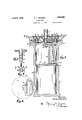
Fig. 1 is a longitudinal cross sectional view of the device of the invention, in locked condition.
Fig. 2 is an elevational View showing in detail a handle-spindle forming part of the invention.
Fig. 3 is a plan view taken on line 33 of Fig. 2.
Fig. 1 is a bottom plan view of a movable carrier plate forming a detail of the invention.
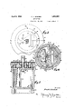
Fig. 5 is a cross sectional view taken on line 55 of Fig. 1.
Fig. 6 is a cross sectional view taken on line 66 of Fig. 1.
Fig. 7 is a cross sectional view similar to Fig. 1, showing the device in the unlocked condition.
The device of this invention comprises a receptacle 8 adapted to be partially buried in a concrete block, or suitably secured to some other firm support, and provided at its upper end with an opening 9'for reception of a rotatable door 10. The body of the receptacle is provided with a series of longitudinal arcuate lugs 12, beneath which lugs the complementary similar lugs 13 of the door may be disposed, upon rotating the door, to preclude lifting of the door from the opening 9. While the lugs are disposed in the operative position above described, the locking bolt 14 of the door mav be caused to enter arecess 15 in the wall of opening 9 for the purpose of precluding rotational movement of the door by means of the handle-spindle indicated at 16. Withdrawal of the bolt and rotation of the door until the lugs 12 and 13 disengage, permits lifting of the door and affords access to the interior of the receptacle. It is undera stood, therefore, that the body 10 of the door normally is fixed against movement'relative to the receptacle.
The door body 10 is provided with an opening 17 for reception of the normally rotatable handlespindle 16 which carries the fixed plate- like elements 18 and 19 both of which are adapted to rotate with the handle-spindle. The elements 18 and'19 hereafter will be referred to as the guard plate and the movable carrier support respectively. 2
The guard plate 18, door 10, and the carrier support 19, are provided with deposit receivslots or openings 20, 21 and 22, respectively, which slots or openings may be caused to register with one another by manually rotating the handle-spindle 16 to the position shown in Fig. 1. Articles inserted into the opening 20 thereby may be caused to drop through the openings 21 and 22 and into the horn shaped or tubular carrier 23. The articles thus disposed within the tubular carrier will rest upon a smooth surfaced division plate 24, which plate has an opening or slot 25 remote from the normal position of 1, the carrier 23 and with which the carrier may be placed in registration by actuating the handle-spindle. By rotating the carrier support 19 to a proper position, the carrier 23 will register with the opening 25 and the 18 and 19 may be rotated for disengagement of the lugs 12 and 13, as hereinbefore described, and lifted bodily from the receptacle. Thereafter, the division plate 24 may be lifted from its position on the annular shoulder 28 and removed bodily from the receptacle, thereby affording free and unrestricted access to the compartment 26. The division plate may be precluded from rotational movement within the receptacle by means of a stud 29 received in a slotor opening 80 of the plate; the plate is not necessarily secured to the receptacle 8.
The guard plate 18 and the carrier support 19 may be caused to rotate with the spindle by providing flat portions 31 and 32 on the spindle adapted for reception in the angular perforations 33 and 34, respectively, of the members 18 and 19. This connection, however, could be made by a welding or shrinking process, or by means of any suitable securing devices such as pins or screws. A nut 35 or its equivalent may engage the lower end of the spindle for maintaining the plate 19 in position thereon.
' Reference to Fig. 5 renders clear the size and location of the opening 25 of plate 24.
The edges of said opening normally are not parallel with those of the tubular carrier, but are disposed at an angle thereto so that rotation of the tubular carrier through an are exceeding 180 degrees is required for effecting registration of the tubular carrier with the opening 25. By means of this construction it is rendered impossible to fish out the contents of the depository with a hooked wireor'other device designed for that pur pose, since the opening 20 of the guard plate will be completely. closed by the body of the door when. the carrier is in registration with opening 25. The opening 25 is madeslightly larger than that of the tubular carrier so as to insure immediate unrestricted dropping of articles from the carrier into the opening 25 when placed in registration. A suitable stationary stop 36 serves to limit rotational movement of the carrier tube and said stop may be carried by any stationary part of the rdevice, such asplate 24. The stop preferably is so located as to permit rotation of the carrier tube farther than the registry position with the opening 25, the purpose of such stop location being to confuse one who is not familiar with theconstruction of the device, and thereby preclude determination of the locationof the opening 25. The stop 86 may also limit backward rotation of the elements 18 and 19. r
The door 10 is provided with a suitable lock 27 that may be actuated by means of one or more keys. Thekey receptacles of the lock are indicated at 37, and they are so arranged in the door 10 that rotational movement of the guard plate 18 may cause the opening 20 thereof to register with the key receptacles, (Fig. 7), thereby possible the insertion of a key or keys. Except when in registration with the slot oropening 20, the key receptacles and-lockare protected from dirt and foreign substances by the guard plate or shield 18. As indicated in Figs. 1 and 7, the guard plate also serves a protective cover for the door jamb, which the cover overhangs. The door fmay comprise a number of plate members secured together by the screws 38.
By means of the construction illustrated in 6, a durable and effective door bolting mechanism is provided. The bolt 14 comprovide a passage through which the dog may bemoved for retraction of the bolt 14 after release thereof by unlocking of the lock means 27.- The bolt has extendingtherefrom a lock bar 41 that enters the lock and normally is held thereby. It will readily be apparent from the disclosure of Fig. 6, that an attempt to force the bolt 14 from the recess 15 results in engagement of the dog 39 with a spindle 16, which precludes injury to the lock 27. It
is to be noted also that the bolt 14 may, by
the arrangement illustrated and described herein, be of sufficient size and strength to effectively resist shearing of the bolt by the application of force tending to rotate the door when locked. The plates 18 and 19 serve to preclude forcible driving off of the lock mechanism by theme of punches and other tools. The locking bolt 14 may be provided witha suitable guide 42 adapted to enter and slide within a guide way 43 formed in the door 10.
The operation of the device is as follows. From any position in which the guard or shield plate 18 covers the passage 21 and the key receptacle 37, the guard plate may be moved, by means ofthe handle-spindle, to cause registration of the three'openings 20, 21 and 22. he article to be deposited may thereupon be dropped into the carrier tube 28, after which the guard plate may be ro- L ill.-
whiclrtime the carrier tube registers with LllG opening 25 through which the deposited article may drop into the compartment 26. The
spindle, guard plate and carrier plate thereafter may be rotated as a unit, to the initial position. The foregoing operation may be repeated any number of times, it being understood that the door 10 is locked, as indicated in Figs. 1 and 6.
To unlock the device, it is necessary to turn the handle-spindle 16 until the opening 20 of the guard plate coincides with the key rcceptacles 37 into which the proper keys may be inserted for unlocking the lock mechanism 27 and'retracting the bolt 14. i It is to be noted that proper alignment of the opening 20 with the locl; 27 causes the cut out port-ion 40 of the spindle to align itself with the locking dog 39, and the locking dog thereby is rendered free to move toward the spindle for effecting withdrawal of the bolt 14 from tho keeper or recess 15. The dog 39, being then in contact with the face 4:0 affords a locked relationship between the spindle and the door, whereby the spindle may be employed for bodily rotating the door and lifting it from its normal'position on the safe or depository. After removal of the door and the parts 18 and 19 associated therewith, the collector may reach into the depository and remove the plate 24:, thereby exposing the contents of the depository.
What is claimed is:
1. A depository comprising in combination a receptacle having a door opening, a bodily removable rotatable door for closing the opening, said door having a deposit receiving opening therein, cooperative door securing means associated with the door and the re ceptacle and adapted to engage and disengage upon rotation of the door, a bolt and a locking mechanism associated therewith for locking the door against rotational movement, a handle-spindle normally rotatable relative to the door, a carrier plate and a guard plate each fixed for movement with the handlespindle and each having an opening therein adapted to register with the deposit receiving opening of the door when the handle spindle is rotated, a division plate in the receptacle having an opening out of alignment with the opening of the door, a guide for deposited articles said guide being movable with the carrier plate and adapted to carry deposited articles to the opening of the division plate when the handle-spindle is rotated, and means associated with the locking mechanism for fixing the handlespindle against rotation relative the door whereby to render the handle-spindle operable for bodily rotating and lifting the door from the receptacle.
2. A depository comprising in combination a receptacle having a door opening, a non mally stationary door for closing the open ing and having a deposit receiving opening therein, a handle-spindle normally rotatable relative to the door and extending therethrough, a carrier support fixed upon the innor end of the handle-spindle and having an opening therein adapted to register With the deposit receiving opening of the door, a perforated division plate supported in the receptacle intermediate its top and bottom, the
perforation of the division plate being disposed in a non-registering position relative to the deposit receiving opening of the door, and a carrier for deposited articles the carrier being movable with the carrier support and adapted to move deposited articles relative the division plate until said articles drop through the perforation of the division plate and into the space below it.
3. A depository comprising in combination a receptacle having a door opening, a normally stationary door for closing the opening and having a deposit receiving opening therein, a handle-spindle normally rotatable relative to the door and extending therethrough, a carrier support fixed upon the inner end of the handle-spindle and having an opening therein adapted to register with the deposit receiving opening of the door, a perforated division plate supported in the receptacle intermediate its top and bottom, the perforation of the division plate being disposed in a nonregistering position relative to the deposit receiving opening of the door, a carrier for a receptacle having a door opening, a normal- 1y stationary door forclosing the opening and having a deposit receiving opening therein, a handle-spindle normally rotatable relative to the door and extending therethrough, a carrier support fixed upon the inner end of the handle-spindle and having an opening therein adapted to register with the deposit receiving opening of the door, a per fora-ted division plate supported in the receptacle intermediate its top and bottom, the
perforation of the division plate being disposed in a non-registering position relative,
to the deposit receiving opening of the door,
a carrier for deposited articles the carrier be-v ing movable with the carrier support and adapted to move deposited articles relative the division plate until said articles drop through the perforation of the division plate and into the space below it, and a guard plate disposed exteriorly of and overhanging the edges of the door and arranged for movement with the spindle and the carrier said guard plate having a perforation therein coinciding with the opening of the carrier sup port and movable to a position in coinciding relationship with the deposit receiving opening of the door.
5. A depository comprising in combination a receptacle having a door opening, a normally stationary 'door for closing the opening and having a deposit receiving opening therein aliaiidle-spindle normally rotatable relative to the door and extending therethrough, a carrier support fixed upon the inner end of the handle-spindle and having an opening therein adapted to register with the deposit receiving opening of the door, a perforated division plate supported in the receptacle intermediate its top and bottom, the perforation of the division plate being disposed in a non-registering position relative to the deposit receiving opening of the door, a carrier for deposited articles the carrier being movable with the carrier support and adapted to move deposited articles relative the division plate until said articles drop through the perforation of the division plate and into the space below it and a stop for limiting rotational movement of the carrier.
6. A depository comprising in combination a receptacle having a door opening, a normally stationary door for closing the opening and having a deposit receiving opening therein, a handle-spindle normally ro-c tatable relative to the door and extending therethrough, a carrier support fixed upon the inner end of the handle-spindle and having an opening therein adapted to register withthe deposit receiving opening of the door, a perforated division plate supported in the receptacle intermediate its top and bottom, the perforation of the divison plate being disposed in a non-registering position relative to the deposit receiving opening of the door, a carrier for deposited articles the carrier being movable with the carrier support and adapted to move deposited articles relative the division. plate until said articles drop through the perforation of the division plate and into the space below it, and a guard plate disposed exteriorly of the door and ar ranged for movement with the spindle and the carrier said guard plate having a perforation therein coinciding with the opening of the carrier support and movable to a position in coinciding relationship with the deposit receiving opening of the door and a ,door lock covered normally by the guard plate but positioned so as to beexposed through the perforation of the guard plate when the guard plate is moved from coinciding relationship with the deposit receiving opening of the door.
'5. A depository comprising in combination a receptacle having a door opening, a
bodily removable rotatable door for closing the opening said door having a deposit-receiving opening therein, cooperative door securing means associated with the door and the receptacle and adapted to engage and disengage upon rotation of the door, a bolt and a locking mechanism associated therewith for locking the door against rotational movement, a handle-spindle normally rotatable relative to the door, a member fixed for move ceiving opening therein, cooperative door securing means associated with the door and the receptacle and adapted to engage and disengage upon rotation of the door, a bolt and a locking mechanism associated therewith for locking the door against rotational movement, a handle-spindle normally rotatable relative to the door, a member fixed for movement with the handle-spindle and havingan opening therein adapted to register with the opening of the door when the hanrile-spindle is rotated and means associated with the locking mechanism for fixing the handle-spindle against rotation relative the door whereby to render the handle-spindle operable for bodily rotating and lifting the door from the receptacle.
9. A depository coinprising n combination a receptacle having a door opening, a bodily removable rotatable door for closing the opening therein, cooperative door securing means associated with the door and the receptacle and adapted to engage upon'rotation of the door, a bolt and a locking mechanism associated therewith for locking the door against rotational movement, a handlespindle normally rotatable relative to the door. a member fixed for movement with the handle-spindle and having an opening therein adapted to register with the opening of the door when the handle-spindle is rotated and means associated with the locking mechanism and operating only when the openings are in non-registering relationship, to fix the handle-spindle against rotation relative the door whereby to render the handle-spindle operable for bodily rotating andlifting the door from the receptacle, 1 r
10. A door for depositories and the like comprising in combination a body portion opening said door having a deposit-receiving .ll
having a deposit receiving opening therein, a rotatable spindle extending through the body portion of the door, a guard plate adj a cent one face of the door and overhanging the edges of the door and having a perforation therein adapted to be placed in registration with the deposit receiving opening of the door body, means for fixing the guard plate relative to the rotatable spindle, and a carrier fixed relative to the spindle and disposed adjacent another face of the door, said carrier having an opening therein coinciding with the opening of the guard plate and movable with the spindle to a position in registration with the deposit receiving opening of the door body.
11. A door for depositories and the like comprising in combination a body portion having a deposit receiving opening therein, a rotatable spindle extending through the body portion of the door, a guard plate adjacent one face of the door and overhanging the edges of the door and having a perforation therein adapted to be placed in registration with the deposit receiving opening of the door body, means for fixing the guard plate relative to the rotatable spindle, and a carrier fixed relative to the spindle and di posed adjacent another face of the door, said carrier having an opening therein coinciding with the opening of the guard plate and movable with the spindle to a position in registration with the deposit receiving opening of the door body and a door lock normally covered by the guard plate but rendered accessible through the guard plate perforation upon rotation of the spindle.
12. A door for depositories and the like comprising in combination a body portion having a deposit receiving opening therein, a rotatable spindle extending through the body portion of the door, a guard plate adjacent one face of the door overhanging the edges of the door and having a perforation therein adapted to be placed in registration with the deposit receiving opening of the door body, means for fixing the guard plate relative to the rotatable spindle, and a carrier fixed relative to the spindle and disposed adjacent another face of the door, said'carrier having an opening therein coinciding with the opening of the guard plate and movable with the spindle to a position in registration with the deposit receiving opening of the door body.
13. A door for depositories and the like comprising in combination a body portion, a normally rotatable handle-spindle extending through the body portion, a lock supported by the door, a lock bolt slidably mounted relative the door and having a portion normally extending beyond the door for reception in a keeper, a dog on the lock bolt adapts ed to substantially abut the spindle while the bolt is extended so as to preclude forcible retraction of the bolt and injury to the look, a lock bar extending from the bolt and received by the lock and secured thereby for maintaining the bolt in an extended locked position, and a way in the normally rotatable spindle and into which way the dog may enter, upon predetermined rotation of the spindle, for permitting retraction of the bolt and for locking the spindle against rotation relative the door.
14. A bodily rotatable door for depositories and the like comprising in combination a body portion, a normally rotatable handlespindle extending through the body portion, a lock supported by the door, a lock bolt slidably mounted relative the door and having a portion normally extending beyond the door for reception in a keeper, a dog on the lock bolt adapted to substantially abut the spindle while the bolt is extended so as to preclude forcible retraction of the bolt and injury to the look, a lock bar extending from the bolt and received by the lock and secured thereby for maintaining the bolt in an extended locked position, and a way in the normally rotatable spindle and into which way the dog may enter, upon predetermined rotation of the spindle, for permitting retraction of the bolt and for locking the spindle against rotation relative the door so that said spindle may be used for bodily rotating the door.
15. A door for depositories and the like comprising in combination a body portion having a deposit receiving opening therein, a rotatable spindle extending through the body portion of the door, a guard plate adjacent one face of the door and having a perforation therein adapted to be placed in registration with the deposit receiving opening of the door body, means for fixing the guard plate relative to the rotatable spindle, a carrier plate fixed relative to the spindle and disposed adjacent another face of the door, said carrier plate having an opening therein coinciding with the opening of the guard plate and movable with the spindle to a position in registration with the deposit receiving opening of the door body and a lock supported by the door body intermediate the guard plate and the carrier plate, whereby the carrier plate serves always as an abutment for precluding forcible downward displacement of the look.
In testimony whereof, I have hereunto subscribed my name this 22 day of October, 1931.
FRANK J. JENDREK.
Priority Applications (1)
| Application Number | Priority Date | Filing Date | Title |
|---|---|---|---|
| US572346A US1852053A (en) | 1931-10-31 | 1931-10-31 | Depository |
Applications Claiming Priority (1)
| Application Number | Priority Date | Filing Date | Title |
|---|---|---|---|
| US572346A US1852053A (en) | 1931-10-31 | 1931-10-31 | Depository |
Publications (1)
| Publication Number | Publication Date |
|---|---|
| US1852053A true US1852053A (en) | 1932-04-05 |
Family
ID=24287387
Family Applications (1)
| Application Number | Title | Priority Date | Filing Date |
|---|---|---|---|
| US572346A Expired - Lifetime US1852053A (en) | 1931-10-31 | 1931-10-31 | Depository |
Country Status (1)
| Country | Link |
|---|---|
| US (1) | US1852053A (en) |
Cited By (7)
| Publication number | Priority date | Publication date | Assignee | Title |
|---|---|---|---|---|
| US3417715A (en) * | 1967-05-23 | 1968-12-24 | Joseph P. Krieger | Lockable key-holding receptacle |
| US3481288A (en) * | 1968-04-05 | 1969-12-02 | Walter Teleky | Wall safe |
| US3672563A (en) * | 1970-10-14 | 1972-06-27 | Dover Corp | Valuables depository |
| US4080908A (en) * | 1977-02-07 | 1978-03-28 | Bianco Eric L | Shutter assembly for slot or aperture |
| US4674416A (en) * | 1984-09-06 | 1987-06-23 | Mcgraw Thomas F | Optical disk storage safe |
| US5131797A (en) * | 1991-03-21 | 1992-07-21 | The United States Of America As Represented By The United States Department Of Energy | Swipe transfer assembly |
| US5607102A (en) * | 1995-12-11 | 1997-03-04 | Walsh; Michael J. | Tamper-resistant cash box |
-
1931
- 1931-10-31 US US572346A patent/US1852053A/en not_active Expired - Lifetime
Cited By (8)
| Publication number | Priority date | Publication date | Assignee | Title |
|---|---|---|---|---|
| US3417715A (en) * | 1967-05-23 | 1968-12-24 | Joseph P. Krieger | Lockable key-holding receptacle |
| US3481288A (en) * | 1968-04-05 | 1969-12-02 | Walter Teleky | Wall safe |
| US3672563A (en) * | 1970-10-14 | 1972-06-27 | Dover Corp | Valuables depository |
| US4080908A (en) * | 1977-02-07 | 1978-03-28 | Bianco Eric L | Shutter assembly for slot or aperture |
| US4674416A (en) * | 1984-09-06 | 1987-06-23 | Mcgraw Thomas F | Optical disk storage safe |
| US5131797A (en) * | 1991-03-21 | 1992-07-21 | The United States Of America As Represented By The United States Department Of Energy | Swipe transfer assembly |
| US5607102A (en) * | 1995-12-11 | 1997-03-04 | Walsh; Michael J. | Tamper-resistant cash box |
| WO1997021899A3 (en) * | 1995-12-11 | 1997-09-04 | Michael J Walsh | Tamper-resistant cash box |
Similar Documents
| Publication | Publication Date | Title |
|---|---|---|
| US4229956A (en) | Locking mechanism | |
| US5092143A (en) | Lockable enclosure having a tamper-proof locking assembly | |
| US3083563A (en) | Theft proof lock assembly for coin operated machines | |
| US5261258A (en) | Padlock protector | |
| US4037700A (en) | Coin vault | |
| US3334501A (en) | Protective device for locks | |
| US1852053A (en) | Depository | |
| US3444712A (en) | Lock and improved guard therefor | |
| US3851942A (en) | Meter box with vault latch | |
| US3808984A (en) | Security device | |
| US1060018A (en) | Safe-deposit box. | |
| US4031730A (en) | Tamperproof lock and method | |
| US3333764A (en) | Double lock coin box for vending machines | |
| US3705504A (en) | Chain door latch device | |
| US1954668A (en) | Safe | |
| US1954667A (en) | Safe | |
| US3031133A (en) | Bank night depository entrance | |
| US1887866A (en) | Double door floor safe | |
| US1567811A (en) | Doorlock | |
| US3315622A (en) | Vault | |
| US1122550A (en) | Vault-door lock. | |
| US2666607A (en) | Support for coin controlled machines | |
| US2065142A (en) | Locking mechanism | |
| US1933263A (en) | Coin controlled lock | |
| US3214089A (en) | Token collection device |