US1852051A - Telegraph repeater system - Google Patents
Telegraph repeater system Download PDFInfo
- Publication number
- US1852051A US1852051A US543917A US54391731A US1852051A US 1852051 A US1852051 A US 1852051A US 543917 A US543917 A US 543917A US 54391731 A US54391731 A US 54391731A US 1852051 A US1852051 A US 1852051A
- Authority
- US
- United States
- Prior art keywords
- sending
- repeater
- loop circuit
- incoming
- relay
- Prior art date
- Legal status (The legal status is an assumption and is not a legal conclusion. Google has not performed a legal analysis and makes no representation as to the accuracy of the status listed.)
- Expired - Lifetime
Links
Images
Classifications
-
- H—ELECTRICITY
- H04—ELECTRIC COMMUNICATION TECHNIQUE
- H04L—TRANSMISSION OF DIGITAL INFORMATION, e.g. TELEGRAPHIC COMMUNICATION
- H04L27/00—Modulated-carrier systems
- H04L27/02—Amplitude-modulated carrier systems, e.g. using on-off keying; Single sideband or vestigial sideband modulation
Definitions
- This invention relates to telegraph systems employing carrier channels for the transmission of a plurality of messages and more particularly to improvements in repeater arrangements for interconnecting the circuits of such systems.
- the output of a carrier telegraph detector at the repeater station is passed to the loopclrcult there at and operates a sensitive relay at the subscribers office.
- a resistance network is provided associated with the grid of the sending amplifier of an outgoing channel at the repeater, whereby a comparatively high negative potential 1s a.pplied to the grid of the sending amplifier whenever'the incoming signal from an associated channel is a spacing one or when the printer transmitter or subscribers key in the repeater loop circuit is open. This would stop the flow of carrier from the sendmg amplifier to the line.
- a marking signal is received over the incoming channel relay means in the loop circuit at the repeater Wlll 1931.
- plifier and carrier current may be transmits ted to the outgoing line.
- Special biasing cir cults are provided by the arrangements of the invention for the relays at the repeater to insure the proper transmission of a break slgnal from the subscribers loop circuit thereat.
- Fig. 1 illustrates the repeater arrangements of the invention as applied to a. half duplex telegraph system, while the repeater arrangements of Fig. 2 are shown asapplied to a full duplex telegraphsystem. Similar reference characters have been 'util ized to denote like parts in both figures.
- Fig. l therepeater arrangements of the invention are shown as applied to a half duplex telegraph system.
- incoming line L is shown including a selective circuit or filter such as RF and an amplifier 89.
- the output circuit of the amplifier would be'connected to a detector 32.; The outputof the detector 32 may be transmitted to a loopcircuit 50 and operate a sensitive relay 51 therein, thus eliminating the need for a receiving; relay for repeating the signals from the line L to the loop circuit 50.
- An outgoing line L is shown to which it is desired to repeat the signals coming in over line L
- the outgoing line L includes a selective cit-1 cuit or filter SF and a sending amplifier 24 the input of which is connected to an OS: cillator 59.
- the grid of the sending amplifier 24 will be connected to aresistance network R R Gonnectedjbyth'e resistance network to the gridof sending amplifier 24 is a relatively high source of negative potential 27.
- An outgoingcircuit L is shown including a selective circuit or 'filter SF and'a sending'amplifier 43, the input of which is connected to an oscillator 60.
- a resistance network R R Connected to the grid of sending amplifier 43 is a resistance network R R A relatively high negative potential maybe applied from the battery 42 to the grid of amplifier 43 and under certain conditionswill block the amplifier and prevent carrier from being transmitted from the oscillator 60 to the line L.
- a marking signal is transmitted over the line L the relay 57 will operate and hold its armature to its marking contact. Under these conditions a positive potential from the battery 53 would be applied over the loop circuit and marking contact of relay 57 to the resistance network R R and will applied to the amplifier 43. This will allow the amplifier 43 to function and will allow carrier to be transmitted from oscillator to the line L thus repeatingthe incoming signal.
- the incoming signals from either the line L or L will be transmitted over the loop circuit 50 and operate a sensitive relay 51 therein.
- the relays 57 and 58 each have two biasing windings and one operating winding.
- the operating windingis 96 and the biasing windings are 95 and 94.
- the biasing winding 95' obtains current from the loop circuit 50 and tends to hold its armature. to spacing.
- the other biasing winding 94 tends to hold the armature to marking.
- the force exerted by winding 95 to move the armature to the spacing contact isgreater'than that exerted by winding 94 to move the armature to the marking contact by an amount one-half as great as d the force, exerted by winding 96 to move thearmature to the marking contact.
- the relay armature will be held to the marking contact however, by a current of 3 mils in the biasing winding 94.
- a spacing signal is received from the line the relay armature operates to spacing due to the 6 mils spacing current in the biasing winding 95 overcoming the 3 mils marking current in the biasing winding 94.
- Relay 57' is similar in structure and operation to rel-ay 58; l/Vhen a spacing signal or. break signal is received from loop 50 by reason of theopening of the key 52 the armatures of both relays 57 and 58 are held firmly to marking by the current flowing in windings 93 and 94, respectively, regardless of any incoming signals from either line L or line L thus providing a good break signal.
- positive potential from battery 53 may be applied to or dis-Q connected from the resistance networks R R and R E by means of the armatures and contacts of relays 57 and 58.
- the 0perativeness of amplifiers 24 and 43 may thus be controlled by the incoming signals.
- the arrangements described provide great flexibility in patching between incoming and outgoing lines at the repeater due to thefact that separate oscillators are provided for each of the outgoinglines, Accordingly, the: carrierfrequency of the incoming lines may be different from the carrier frequency used on the outgoing lines.
- Fig. 2 a modification of the arrangements of the invention is shown as applied to an intermediate repeaterfor a full duplex system.
- the arrangements are substantially similar to those of Fig. 1 except that relays 57 and 58 have only one'biasing winding.
- the biasing windings 93 and 94in Fig. 2 would tend to hold the relay armatures on their spacing contacts.
- the current therein would be overcome by vthe marking current through windings 91 and 96 from, the lines L and L
- Theloop battery 66 is made common to both loops 60 and 63, thus providing an arrangement for sending simultaneously to the east or west linesby connecting the telegraph keys in this common branch.
- similar reference characters have been used to denote like partswith respect to Fig. 1.
- As the operation of the arrangements of Fig. 2 is inother respects similar to that heretofore described Withfrespect to Fig. 1 no further description there varied forms without departing from the spirit of the invention as defined by the appended claims.
- a repeater ar controlling the application of a blocking potential to said sending amplifiers.
- a repeater arrangement comprising incoming and outgoing transmission channels for transmission in one direction, incoming and outgoing transmission channels for transmission in the other direction, each of said incoming channels including receiving amplifiers and detectors, each of said outgoing channels including sending amplifiers and sources of signaling current connected to the input thereof, means for applying a relatively high'negative potential to the grids of said sending amplifiers to render them inoperative, a subscribers loop circuit connected to the output of said detectors, relay means controlled by said loop circuit and the output of said detectors, and means controlled by said relays for reducing the negative potential applied to the grids of said sending amplifiers to render them operative.
- a repeater arrangement comprising incoming and outgoing transmission channels for transmission in one direction, incoming and outgoing channels for transmission in the other direction, each of said incoming channels including receiving amplifiers and detectors, eachof said outgoing channels including sending amplifiers and sources of signaling current connected to the input thereof, resistance networks connected to the grids of said sending amplifiers, means for applying a relatively high negative potential to said resistance networks to render said sending amplifiers inoperative, a subscribers loop circuit connected to the output of said detectors, means for applying to said loop circuit a positive potential sufficient when applied to said networks to reduce the negative potential applied to said sending amplifiers and thus render them operative, and relay means controlled by said loop circuit and the output of said detectors for connecting said loop circuit to said resistance networks.
- a repeater arrangement comprising incoming and outgoing transmission channels for transmission in one direction, incoming and outgoing transmission channels for transmission in the other direction, each of said incoming channels including receiving amplifiers and detectors, each of said outgoing channels including sending amplifiers and sources of signaling current connected to the input thereof, resistance networks connected to the grids of said sending amplifiers, means for applying a relatively high negative potential to said resistance networks to render said sending amplifiers inoperative, a subscribers loop circuit connected to the output of said detectors, means for applying to said loop circuit a positive potential suflicient when applied to said networks to reduce the negative potential applied to said sending amplifiers and thus render them v0perative, and relay means controlled by said loop circuit and the output of said detector for connecting said loop circuit to said resistance networks, each of said relays having an operating winding in the output of the detector, a biasing winding in the loop circuit designed to hold the relay armature to its spacing contact and a second biasing winding designed to hold the relay armature to its marking contact, the resultant
Landscapes
- Engineering & Computer Science (AREA)
- Computer Networks & Wireless Communication (AREA)
- Signal Processing (AREA)
- Interface Circuits In Exchanges (AREA)
Description
April 5, 1932- B. P. HAMILTON ET AL TELEGRAPH REPEATER SYSTEM Filed June 12, 1931 Detector Detectoz 5 Osczb Zatvr Detector 32 INVENTORS 0215014,; WZ Rea- ATTORNEY Patented Apr. 5, 1932 TES.
PAT
BAXTEE P. HAMILTON, OF RIVER EDGE, NEW JERSEY, AND WILTON REA, 0F FLUSH ING, NEW YORK, ASSIGNOIRS TO AMERICAN TELEPHONE AND TELEGRAPH COM} PANY, .A. CORPORATION OF NEW YORK TELEGRAPH REPEATER SYSTEM Application filed June 12,
This invention relates to telegraph systems employing carrier channels for the transmission of a plurality of messages and more particularly to improvements in repeater arrangements for interconnecting the circuits of such systems.
In telegraph systems of the radio or wired carrier type it has been the practice to pro-.
vide at the terminals of the lines and at intermediate repeater points, relays for sending signals, relays for receiving signals, and relays for transmitting break signals. It is one of the primary objects of the arrangements of the invention to provide repeater arrangements for a carrier telegraph system in which the number of relays for sending, receiving, or breakingmay be greatly reduced. The elimination of a large number of relays from a telegraph system would result in the advantages of reduced expense and maintenance. A further advantage of the repeater arrangements of the invention is that full flexibility in patching together of different channels of different frequencies at the repeater is provided. Other objects and features of the invention will appear more fully from the detailed description thereof hereinafter given.
In the arrangements of the invention the output of a carrier telegraph detector at the repeater station is passed to the loopclrcult there at and operates a sensitive relay at the subscribers office. This eliminates the need for the receiving relay heretofore used at the channel terminal for repeating signals from the incoming channel to a loop circuit or to an outgoing channel. For sending purposes a resistance network is provided associated with the grid of the sending amplifier of an outgoing channel at the repeater, whereby a comparatively high negative potential 1s a.pplied to the grid of the sending amplifier whenever'the incoming signal from an associated channel is a spacing one or when the printer transmitter or subscribers key in the repeater loop circuit is open. This would stop the flow of carrier from the sendmg amplifier to the line. When a marking signal is received over the incoming channel relay means in the loop circuit at the repeater Wlll 1931. Serial No. 543,917;
be operated thereby and will apply positive grid potential of the sending amplifier to the proper valueso that it will operate as anam- ENT; OFFICE.
plifier and carrier current may be transmits ted to the outgoing line. Special biasing cir cults are provided by the arrangements of the invention for the relays at the repeater to insure the proper transmission of a break slgnal from the subscribers loop circuit thereat. I
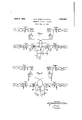
The invention may be more fully understood from the following description together with the accompanying drawings in the Figures 1 and 2 of which the invention is il-' lustrated. Fig. 1 illustrates the repeater arrangements of the invention as applied to a. half duplex telegraph system, while the repeater arrangements of Fig. 2 are shown asapplied to a full duplex telegraphsystem. Similar reference characters have been 'util ized to denote like parts in both figures. In Fig. l therepeater arrangements of the invention are shown as applied to a half duplex telegraph system. In incoming line L is shown including a selective circuit or filter such as RF and an amplifier 89. The output circuit of the amplifier would be'connected to a detector 32.; The outputof the detector 32 may be transmitted to a loopcircuit 50 and operate a sensitive relay 51 therein, thus eliminating the need for a receiving; relay for repeating the signals from the line L to the loop circuit 50. An outgoing line L is shown to which it is desired to repeat the signals coming in over line L The outgoing line L includes a selective cit-1 cuit or filter SF and a sending amplifier 24 the input of which is connected to an OS: cillator 59. The grid of the sending amplifier 24 will be connected to aresistance network R R Gonnectedjbyth'e resistance network to the gridof sending amplifier 24 is a relatively high source of negative potential 27. This, under certain conditions, would block the amplifier 24Land stoprthe flow of carrier current fromthe oscillator 59 to the line L However, whena marking signal is transmitted to the repeater over the line L the relay 58 will be operated and hold its armature on its marking contact. Under these conditions a positive potential from the battery 53 will be transmitted over the loop circuit 50 and marking contact of relay 58 to the resistance network R R This will reduce the negative potential applied from battery .27 to the grid of the sending amplifier and allow it to function as an amplifier and thus repeat the carrier signal on out over the line L For repeat ing signals in the other direction the line L is shown including a selective circuit or filter RF and an amplifier 28 the output of which is connected to a detector 29.-
An outgoingcircuit L is shown including a selective circuit or 'filter SF and'a sending'amplifier 43, the input of which is connected to an oscillator 60. Connected to the grid of sending amplifier 43 is a resistance network R R A relatively high negative potential maybe applied from the battery 42 to the grid of amplifier 43 and under certain conditionswill block the amplifier and prevent carrier from being transmitted from the oscillator 60 to the line L When a marking signal is transmitted over the line L the relay 57 will operate and hold its armature to its marking contact. Under these conditions a positive potential from the battery 53 would be applied over the loop circuit and marking contact of relay 57 to the resistance network R R and will applied to the amplifier 43. This will allow the amplifier 43 to function and will allow carrier to be transmitted from oscillator to the line L thus repeatingthe incoming signal. The incoming signals from either the line L or L will be transmitted over the loop circuit 50 and operate a sensitive relay 51 therein.
' The relays 57 and 58 each have two biasing windings and one operating winding. For example, in relay 58 the operating windingis 96 and the biasing windings are 95 and 94. The biasing winding 95' obtains current from the loop circuit 50 and tends to hold its armature. to spacing. The other biasing winding 94 tends to hold the armature to marking. The force exerted by winding 95 to move the armature to the spacing contactisgreater'than that exerted by winding 94 to move the armature to the marking contact by an amount one-half as great as d the force, exerted by winding 96 to move thearmature to the marking contact. These arrangements are provided in order to obtain a clear-cut break signal from the subscribers loop 50. For example, assume a current of 6 mils, receivedfrom the line L as a marking signal, to be flowing through winding 96.. This might be neutralized by a current of 6 mils in biasing winding 95 which. is obtained from the loop circuit.
The relay armature will be held to the marking contact however, by a current of 3 mils in the biasing winding 94. When a spacing signal is received from the line the relay armature operates to spacing due to the 6 mils spacing current in the biasing winding 95 overcoming the 3 mils marking current in the biasing winding 94. Relay 57'is similar in structure and operation to rel-ay 58; l/Vhen a spacing signal or. break signal is received from loop 50 by reason of theopening of the key 52 the armatures of both relays 57 and 58 are held firmly to marking by the current flowing in windings 93 and 94, respectively, regardless of any incoming signals from either line L or line L thus providing a good break signal. As 'hasbeen heretofore pointed out, positive potential from battery 53 may be applied to or dis-Q connected from the resistance networks R R and R E by means of the armatures and contacts of relays 57 and 58. The 0perativeness of amplifiers 24 and 43 may thus be controlled by the incoming signals.
The arrangements described provide great flexibility in patching between incoming and outgoing lines at the repeater due to thefact that separate oscillators are provided for each of the outgoinglines, Accordingly, the: carrierfrequency of the incoming lines may be different from the carrier frequency used on the outgoing lines.
In Fig. 2 a modification of the arrangements of the inventionis shown as applied to an intermediate repeaterfor a full duplex system. The arrangements are substantially similar to those of Fig. 1 except that relays 57 and 58 have only one'biasing winding. The biasing windings 93 and 94in Fig. 2 would tend to hold the relay armatures on their spacing contacts. The current therein would be overcome by vthe marking current through windings 91 and 96 from, the lines L and L Theloop battery 66 is made common to both loops 60 and 63, thus providing an arrangement for sending simultaneously to the east or west linesby connecting the telegraph keys in this common branch. In Fig. 2 similar reference characters have been used to denote like partswith respect to Fig. 1. As the operation of the arrangements of Fig. 2 is inother respects similar to that heretofore described Withfrespect to Fig. 1 no further description there varied forms without departing from the spirit of the invention as defined by the appended claims.
What is claimed is 1. In a telegraph system a repeater ar controlling the application of a blocking potential to said sending amplifiers.
2. In a telegraph system a repeater arrangement comprising incoming and outgoing transmission channels for transmission in one direction, incoming and outgoing transmission channels for transmission in the other direction, each of said incoming channels including receiving amplifiers and detectors, each of said outgoing channels including sending amplifiers and sources of signaling current connected to the input thereof, means for applying a relatively high'negative potential to the grids of said sending amplifiers to render them inoperative, a subscribers loop circuit connected to the output of said detectors, relay means controlled by said loop circuit and the output of said detectors, and means controlled by said relays for reducing the negative potential applied to the grids of said sending amplifiers to render them operative.
3. In a telegraph system a repeater arrangement comprising incoming and outgoing transmission channels for transmission in one direction, incoming and outgoing channels for transmission in the other direction, each of said incoming channels including receiving amplifiers and detectors, eachof said outgoing channels including sending amplifiers and sources of signaling current connected to the input thereof, resistance networks connected to the grids of said sending amplifiers, means for applying a relatively high negative potential to said resistance networks to render said sending amplifiers inoperative, a subscribers loop circuit connected to the output of said detectors, means for applying to said loop circuit a positive potential sufficient when applied to said networks to reduce the negative potential applied to said sending amplifiers and thus render them operative, and relay means controlled by said loop circuit and the output of said detectors for connecting said loop circuit to said resistance networks.
4. In a telegraph system a repeater arrangement comprising incoming and outgoing transmission channels for transmission in one direction, incoming and outgoing transmission channels for transmission in the other direction, each of said incoming channels including receiving amplifiers and detectors, each of said outgoing channels including sending amplifiers and sources of signaling current connected to the input thereof, resistance networks connected to the grids of said sending amplifiers, means for applying a relatively high negative potential to said resistance networks to render said sending amplifiers inoperative, a subscribers loop circuit connected to the output of said detectors, means for applying to said loop circuit a positive potential suflicient when applied to said networks to reduce the negative potential applied to said sending amplifiers and thus render them v0perative, and relay means controlled by said loop circuit and the output of said detector for connecting said loop circuit to said resistance networks, each of said relays having an operating winding in the output of the detector, a biasing winding in the loop circuit designed to hold the relay armature to its spacing contact and a second biasing winding designed to hold the relay armature to its marking contact, the resultant of the forces exerted by said two biasing windings being opposite in direction to and approximately one half as great in magnitude as the force exerted by the operating windmg,
I11 testimony whereof, we have signed our names to this specification this 10th day of June 1931.
BAXTER P. HAMILTON. WILTON 'I. REA. 7
Priority Applications (1)
| Application Number | Priority Date | Filing Date | Title |
|---|---|---|---|
| US543917A US1852051A (en) | 1931-06-12 | 1931-06-12 | Telegraph repeater system |
Applications Claiming Priority (1)
| Application Number | Priority Date | Filing Date | Title |
|---|---|---|---|
| US543917A US1852051A (en) | 1931-06-12 | 1931-06-12 | Telegraph repeater system |
Publications (1)
| Publication Number | Publication Date |
|---|---|
| US1852051A true US1852051A (en) | 1932-04-05 |
Family
ID=24170047
Family Applications (1)
| Application Number | Title | Priority Date | Filing Date |
|---|---|---|---|
| US543917A Expired - Lifetime US1852051A (en) | 1931-06-12 | 1931-06-12 | Telegraph repeater system |
Country Status (1)
| Country | Link |
|---|---|
| US (1) | US1852051A (en) |
Cited By (1)
| Publication number | Priority date | Publication date | Assignee | Title |
|---|---|---|---|---|
| US2639320A (en) * | 1950-12-22 | 1953-05-19 | Bell Telephone Labor Inc | Telegraph trunk and control circuits |
-
1931
- 1931-06-12 US US543917A patent/US1852051A/en not_active Expired - Lifetime
Cited By (1)
| Publication number | Priority date | Publication date | Assignee | Title |
|---|---|---|---|---|
| US2639320A (en) * | 1950-12-22 | 1953-05-19 | Bell Telephone Labor Inc | Telegraph trunk and control circuits |
Similar Documents
| Publication | Publication Date | Title |
|---|---|---|
| US2018464A (en) | Voice operated transmission circuit | |
| US1852051A (en) | Telegraph repeater system | |
| US2198344A (en) | Electrical signal repeating system | |
| US1919046A (en) | Selective calling circuits | |
| US2187104A (en) | Signaling system | |
| US1521685A (en) | Carrier telegraph circuits | |
| US1521671A (en) | Carrier telegraph circuits | |
| US1469253A (en) | Carrier telegraph circuits | |
| US1978020A (en) | Break circuit for telegraph systems | |
| US3647966A (en) | Apparatus for connecting transmission channels | |
| GB371861A (en) | Improvements in telegraph exchange systems | |
| US1875935A (en) | Dot insertion | |
| US2468574A (en) | Selective control of printer motors at outlying telegraph stations | |
| US2060250A (en) | Combined teleprinter and telephone system | |
| US1472463A (en) | Telegraph repeating system | |
| US2056277A (en) | Telegraph repeating system | |
| US1906338A (en) | Telephone system | |
| US1736786A (en) | Telegraph repeater circuits | |
| US1634299A (en) | Telegraph circuits | |
| US1752347A (en) | Reduction of atmospheric disturbance | |
| US2019597A (en) | Repeater | |
| US2232063A (en) | Arrangement for the transmission of intelligence | |
| US1857238A (en) | Transmission system | |
| US1511326A (en) | Duplex telegraphy | |
| US3819868A (en) | Common control switching network for telegraph and telephone exchange |