US1852038A - Tub cover rimmer - Google Patents
Tub cover rimmer Download PDFInfo
- Publication number
- US1852038A US1852038A US460443A US46044330A US1852038A US 1852038 A US1852038 A US 1852038A US 460443 A US460443 A US 460443A US 46044330 A US46044330 A US 46044330A US 1852038 A US1852038 A US 1852038A
- Authority
- US
- United States
- Prior art keywords
- rimmer
- cover
- tub
- lever
- tub cover
- Prior art date
- Legal status (The legal status is an assumption and is not a legal conclusion. Google has not performed a legal analysis and makes no representation as to the accuracy of the status listed.)
- Expired - Lifetime
Links
Images
Classifications
-
- B—PERFORMING OPERATIONS; TRANSPORTING
- B65—CONVEYING; PACKING; STORING; HANDLING THIN OR FILAMENTARY MATERIAL
- B65D—CONTAINERS FOR STORAGE OR TRANSPORT OF ARTICLES OR MATERIALS, e.g. BAGS, BARRELS, BOTTLES, BOXES, CANS, CARTONS, CRATES, DRUMS, JARS, TANKS, HOPPERS, FORWARDING CONTAINERS; ACCESSORIES, CLOSURES, OR FITTINGS THEREFOR; PACKAGING ELEMENTS; PACKAGES
- B65D45/00—Clamping or other pressure-applying devices for securing or retaining closure members
- B65D45/32—Clamping or other pressure-applying devices for securing or retaining closure members for applying radial or radial and axial pressure, e.g. contractible bands encircling closure member
- B65D45/34—Clamping or other pressure-applying devices for securing or retaining closure members for applying radial or radial and axial pressure, e.g. contractible bands encircling closure member lever-operated
-
- Y—GENERAL TAGGING OF NEW TECHNOLOGICAL DEVELOPMENTS; GENERAL TAGGING OF CROSS-SECTIONAL TECHNOLOGIES SPANNING OVER SEVERAL SECTIONS OF THE IPC; TECHNICAL SUBJECTS COVERED BY FORMER USPC CROSS-REFERENCE ART COLLECTIONS [XRACs] AND DIGESTS
- Y10—TECHNICAL SUBJECTS COVERED BY FORMER USPC
- Y10T—TECHNICAL SUBJECTS COVERED BY FORMER US CLASSIFICATION
- Y10T292/00—Closure fasteners
- Y10T292/20—Clamps
- Y10T292/205—Ring
- Y10T292/212—With expanding or contracting means
- Y10T292/216—Toggle lever
Definitions
- a further object of this invention is to provide a tub cover rimmer which maybe quickly adjusted to fit a number of different sizes of tubs in a iven range.
- a more specific object of this invention is to provide a tub cover rimmer in which lever meansis utilized to draw the split ends of the rimmer toward one another so that the cover and tub will be tightly gripped.
- a further object of this invention is to provide atub cover rimmer which is simple in construction, relatively inexpensive to manufacture, and well adapted for the purpose described.
- the invention consists of the improved tub cover rimmer and all its parts and combina-- tions, as set forth in the claim, and all equiva lents thereof.
- Fig. 1 is a side elevational view of a tub showing the improved rimmer as applied thereto;
- Fig. 2 is a fragmentary view on an enlarged scale showing the ends of the rimmer before they have been drawn together;
- Fig. 3 is a similar View showing the rimmer in clamping position
- Fig. 4 is a fragmentary plan view of the cover and rimmer;- Y
- Fig. 5 is a sectional view taken on line 55 of Fig. 3;
- Fig. 6 is a sectional view 6-6 of Fig. 3;
- Fig. 7 is aside view of a'portion of amodified form of rimmer.
- Fig. 8 is a sectional view taken on line 8-8 of Fig. 7.
- the numeral 10 designates a tub such as is used for packing butter and the like, and the numeral 11 the taken on line 1930.
- Said cover is preferably 7 clamping mechanism which will be described f in detail.
- a link memben 16 has one end pivotally connected to an end of the rimmer as at 17, and has its other end formed with a longitudinal slot 18 having a plurality of transverse slots 19, 20, and 21, connected therewith.
- the upper ends of the transverse slots are slightly enlarged and roundedas at 22.
- a lever member 23 has one end pivoted at an eccentric point as at 24 to the other end of the rimmer.
- the other end of the lever is formed with an inwardly and downwardly projecting tongue 24which is adapted to,
- a headed pin 26 projects outwardly from the lever adjacent the pivoted end thereof. Saidpin extends through the longitudinal slot 18 of the link 16,
- the rimmer in expanded position is placed around the cover and upper edge of a tub, the upper flange 14 being seated n the peripheral groove 12 of the cover.
- the lever 23 and link 16 are in the position shown in Fig. 2.
- the lever 23 is depressed to the position shown in Figs. 1 and 3, the ends of the rimmer being drawn toward one.
- pin 26 is engaged in the innermost transverse slot 21 of the link 16, and if the device is used on a larger tub, the pin is engaged in the slot 19. Thus several adjustments may be obtained.
- hat I claim is: In combination, a container, a cover therefor, a split band surrounding the edge of said cover. and the upper periphery of the con- 7 tainer, said band aving an inwardly extending upper flange and said flange having a recess near one end of the band, and means in connection with the band including a levermovable transversely thereof for drawing the split ends toward one another to lock the cover to the container,.the outer end of the lever having an inwardly extending and downwardly projecting tongue engageable in the recess of the flange of the band and between the band and the edge of the cover for holding the leverin locking position.
Landscapes
- Engineering & Computer Science (AREA)
- Mechanical Engineering (AREA)
- Clamps And Clips (AREA)
Description
April 5, 1932.
.1 YOUNG JR TUB covm RIMMER Filed June 11, 1930 I N VEN TOR.
ATTORNEYS Patented A r. s, 1932 UNITEDN STATES' PATENT OFFICE.
JOHN YOUNG, m. or osnxosn, wIsoONsm, ASSIGNOR 'ro' 'mENAsrm WOODEN wnnn CORPORATION, OF MENASHA, wIsoONsIN, A- CORPORATION OF wIsoONsIN 'r uB oovnn nmmnn Application filed June 11,
covers on butter tubs and the like, in which 1 novel means is employed for removably securing the rimmer in position. v
A further object of this invention is to provide a tub cover rimmer which maybe quickly adjusted to fit a number of different sizes of tubs in a iven range.
A more specific object of this invention is to provide a tub cover rimmer in which lever meansis utilized to draw the split ends of the rimmer toward one another so that the cover and tub will be tightly gripped.
A further object of this invention is to provide atub cover rimmer which is simple in construction, relatively inexpensive to manufacture, and well adapted for the purpose described.
With the above and otherobjects in view, the invention consists of the improved tub cover rimmer and all its parts and combina-- tions, as set forth in the claim, and all equiva lents thereof.
In the accompanying drawings, in which the same reference numerals designate the same parts in all of the views:
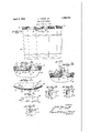
Fig. 1 is a side elevational view of a tub showing the improved rimmer as applied thereto;
Fig. 2 is a fragmentary view on an enlarged scale showing the ends of the rimmer before they have been drawn together;
Fig. 3 is a similar View showing the rimmer in clamping position;
Fig. 4 is a fragmentary plan view of the cover and rimmer;- Y
Fig. 5 is a sectional view taken on line 55 of Fig. 3; A
Fig. 6 is a sectional view 6-6 of Fig. 3;
Fig. 7 is aside view of a'portion of amodified form of rimmer; and
Fig. 8 is a sectional view taken on line 8-8 of Fig. 7.
Referring to the drawings the numeral 10 designates a tub such as is used for packing butter and the like, and the numeral 11 the taken on line 1930. Serial No. 460,443.
cover therefor. Said cover is preferably 7 clamping mechanism which will be described f in detail.
A link memben 16 has one end pivotally connected to an end of the rimmer as at 17, and has its other end formed with a longitudinal slot 18 having a plurality of transverse slots 19, 20, and 21, connected therewith. The upper ends of the transverse slots are slightly enlarged and roundedas at 22.
A lever member 23 has one end pivoted at an eccentric point as at 24 to the other end of the rimmer. The other end of the lever is formed with an inwardly and downwardly projecting tongue 24which is adapted to,
engage a recess 25 in the upper flange of the rimmer when the lever is in looking position as shown in Figs. 3 and 4. A headed pin 26 projects outwardly from the lever adjacent the pivoted end thereof. Saidpin extends through the longitudinal slot 18 of the link 16,
and may be moved into any one of the transverse slots 19, 20, or 21 according to the adjustment desired.-
In use, the rimmer in expanded position is placed around the cover and upper edge of a tub, the upper flange 14 being seated n the peripheral groove 12 of the cover. The lever 23 and link 16 are in the position shown in Fig. 2. Next, the lever 23 is depressed to the position shown in Figs. 1 and 3, the ends of the rimmer being drawn toward one. an-
other, tocause the flanges 14 and 15 to tightly grip the cover and tub so as to secure the cover in position. When the lever is in fully depressed position, the tongue 24 on its free end will engage the recess 25 in the upper flange 14.
If the deviceis used on a smaller tub, the
Although only two forms of the invention have been shown and described, it is not desired to be limited to these exact showings or I to the particular adaptation, as the broad concept of the invention includes all changes and modifications as may come within the sco e of the claim. 1
hat I claim is: In combination, a container, a cover therefor, a split band surrounding the edge of said cover. and the upper periphery of the con- 7 tainer, said band aving an inwardly extending upper flange and said flange having a recess near one end of the band, and means in connection with the band including a levermovable transversely thereof for drawing the split ends toward one another to lock the cover to the container,.the outer end of the lever having an inwardly extending and downwardly projecting tongue engageable in the recess of the flange of the band and between the band and the edge of the cover for holding the leverin locking position. In testimony whereof I aflix my si nature. JOHN YOUN JR.
Priority Applications (1)
| Application Number | Priority Date | Filing Date | Title |
|---|---|---|---|
| US460443A US1852038A (en) | 1930-06-11 | 1930-06-11 | Tub cover rimmer |
Applications Claiming Priority (1)
| Application Number | Priority Date | Filing Date | Title |
|---|---|---|---|
| US460443A US1852038A (en) | 1930-06-11 | 1930-06-11 | Tub cover rimmer |
Publications (1)
| Publication Number | Publication Date |
|---|---|
| US1852038A true US1852038A (en) | 1932-04-05 |
Family
ID=23828728
Family Applications (1)
| Application Number | Title | Priority Date | Filing Date |
|---|---|---|---|
| US460443A Expired - Lifetime US1852038A (en) | 1930-06-11 | 1930-06-11 | Tub cover rimmer |
Country Status (1)
| Country | Link |
|---|---|
| US (1) | US1852038A (en) |
Cited By (4)
| Publication number | Priority date | Publication date | Assignee | Title |
|---|---|---|---|---|
| US3054548A (en) * | 1958-04-16 | 1962-09-18 | Continental Can Co | Locking band for containers |
| DE3432463A1 (en) * | 1984-09-04 | 1986-03-13 | Fa. Theodor Schemm, 5952 Attendorn | Thermoplastic clamping ring |
| US4678216A (en) * | 1986-03-03 | 1987-07-07 | Theodor Schemm | Thermoplastic clamping ring |
| EP0233972A1 (en) * | 1986-02-25 | 1987-09-02 | Firma Theodor Schemm | Thermoplastic tensioning ring |
-
1930
- 1930-06-11 US US460443A patent/US1852038A/en not_active Expired - Lifetime
Cited By (4)
| Publication number | Priority date | Publication date | Assignee | Title |
|---|---|---|---|---|
| US3054548A (en) * | 1958-04-16 | 1962-09-18 | Continental Can Co | Locking band for containers |
| DE3432463A1 (en) * | 1984-09-04 | 1986-03-13 | Fa. Theodor Schemm, 5952 Attendorn | Thermoplastic clamping ring |
| EP0233972A1 (en) * | 1986-02-25 | 1987-09-02 | Firma Theodor Schemm | Thermoplastic tensioning ring |
| US4678216A (en) * | 1986-03-03 | 1987-07-07 | Theodor Schemm | Thermoplastic clamping ring |
Similar Documents
| Publication | Publication Date | Title |
|---|---|---|
| US2287610A (en) | Cream cheese box or carton | |
| US1852038A (en) | Tub cover rimmer | |
| US1250876A (en) | Clothes-line tightener. | |
| US2478994A (en) | Adjusting connector for clotheslines | |
| US1811738A (en) | Musical instrument string securing device | |
| US1688288A (en) | Pudding cloth and the like | |
| US1586174A (en) | Guy-line tightener | |
| US2533275A (en) | Strap fastening means | |
| US1866317A (en) | Container | |
| US1731847A (en) | Bronze and tincture container | |
| US2220366A (en) | Line adjuster | |
| US2914830A (en) | Shoe lace | |
| US1445298A (en) | Envelope fastener | |
| US355057A (en) | Drum-tightener | |
| US493635A (en) | Banjo | |
| US1529560A (en) | Wire stretcher | |
| US438670A (en) | Manson woodman | |
| US1410799A (en) | Fastener for loose sheets of paper or other material | |
| US437604A (en) | Island | |
| US971678A (en) | Ear for pail and bucket bails. | |
| US1709019A (en) | Wire tightener | |
| US1459783A (en) | Mailing tube | |
| US1559286A (en) | Means for carrying cardboard boxes | |
| US1309658A (en) | Tuning-peg adjustment fob stringed musical instruments | |
| US1519368A (en) | Package fastener |