US1852024A - Warp stop motion with unit construction - Google Patents
Warp stop motion with unit construction Download PDFInfo
- Publication number
- US1852024A US1852024A US462651A US46265130A US1852024A US 1852024 A US1852024 A US 1852024A US 462651 A US462651 A US 462651A US 46265130 A US46265130 A US 46265130A US 1852024 A US1852024 A US 1852024A
- Authority
- US
- United States
- Prior art keywords
- bars
- bar
- elements
- members
- stop motion
- Prior art date
- Legal status (The legal status is an assumption and is not a legal conclusion. Google has not performed a legal analysis and makes no representation as to the accuracy of the status listed.)
- Expired - Lifetime
Links
- 230000033001 locomotion Effects 0.000 title description 50
- 238000010276 construction Methods 0.000 title description 8
- 230000006870 function Effects 0.000 description 2
- 230000005484 gravity Effects 0.000 description 2
- 241000501754 Astronotus ocellatus Species 0.000 description 1
- 238000005266 casting Methods 0.000 description 1
- 208000002925 dental caries Diseases 0.000 description 1
- 239000011810 insulating material Substances 0.000 description 1
- 230000004048 modification Effects 0.000 description 1
- 238000012986 modification Methods 0.000 description 1
- 230000036964 tight binding Effects 0.000 description 1
Images
Classifications
-
- D—TEXTILES; PAPER
- D03—WEAVING
- D03D—WOVEN FABRICS; METHODS OF WEAVING; LOOMS
- D03D51/00—Driving, starting, or stopping arrangements; Automatic stop motions
- D03D51/18—Automatic stop motions
- D03D51/20—Warp stop motions
- D03D51/28—Warp stop motions electrical
Definitions
- the present invention relates to an unproved means for supporting thedetector and separator bars or rods of a warp stop motion and it is the general object of the invention to permit enlargement of a relatively narrow stop motion by the addition of substantially similar units which may be clamped together to hold any desired number of detectorand separator bars.
- Looms require different n-umbersot banks of drop wires, depending upon thenature of the warp, gingham for instance calling for but two banks, whereas in some silk looms six banks are necessary. It has previously been customary .to provide a differentset of parts for each different size of warp stop motion, the motion employing only two banks having relatively small castings or parts to support the bars, and the motions having six banks using different and larger parts. It is a further and important object of my present invention to provide supporting strucimre for the contact bars built up of a series of units of similar construction. in this way when it is desired to enlarge atwo-ban-k motion to carry tour or six or any other number of bars greater than two it is necessary merely to add the required number of units.
- Still another object of the invention relates to means for supporting the several unitsso they can be inclined to dispose the pockets or notches for the separatorbars conveniently to hold said bars inplacewithout requiring attention fromthe operator.
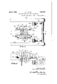
- Fi 1 is a top plan view of the end portions of a warp stop motion made according to my present invention, the centralporti-on of the loom being removed,
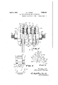
- Fig. 2 is a vertical section on line 2-2 of Fig. l, I
- Fig. 3 is'a' view similar to a portion of Fig. 2 but on an enlarged scale showing one drop wire raised and the other in down or indicating position,
- Fig. 4 is a vertical section on line 4 l of Fig. 3, and
- Fig. 5 is av diagrammatic view showing how the supporting screw be inclined to facilitate assembly; l g V
- the warp stopmotion includes in its" construction a plurality of separator bars above which are located detector bars 11. In the present instance the latter are designed for electrical indication and are made as set forth in the aforesaid application, each bar comprising an outer grounded sheath or inclosing electrode 12within which is the live electrode 1 3. Insulating material 14 between the two electrodes is held in position by the top and bottom curvedor bent edges of the outer inclosing electrode.
- the drop wire D may have a slot 15 into-which extends a pair of substantially similar projections" 16 one of which coa'cts' with the live electrode 13 when the drop wire is in the down position shown at the right handof Fig. 3, and the otherof which cooperates with areinforcing camming rib 17' which extends along and subdetector bar or rod as set forth herein, as the V invention to be described hereinafter is not necessarily limited to an electrical motion.
- the loom frame supports a pair of brackets 21, one located on each side thereof, and each bracket has an upright post22 provided I r with a hub or hearing 23 into which extends a set screw 24.
- Around rod 25 may have the right hand end thereof as viewed in Fig. l
- I provide a plurality of units designated generally at 50.
- the units are substantially similar and a description of adjacent parts of two units and the manner in which they cooperate to hold the contact bar in position between them will suffice as a description for the other units.
- the right hand member of a pair is provided nearthe upper left corner thereof with a short vertical surface 51 to bear against the right upper side of the corresponding contact bar; That part of the left member opposite the surface 51 is provided with a notch 52 into which extends the upper part of the contact bar.
- the horizontal dimension of the notch is slightly less than the thickness of the adjacent part of the contact bar, there being a space 60 between the upper ends of the members to permit clamping of said contact bar in the notch by surface 51.
- the left member has a depression 53 into which projects the crimped part 17 of the contact bar.
- notches 52 and 54 respectively, have parallel horizontal surfaces which are spaced by a distance substantially equal to the height of the contact bar, so that the latter acts to prevent angular movement of the member 50 which receives it.
- the right member 50 may have a downwardly facing horizontal surface 56 to engage the bottom of notch 54 and prevent relative motion between adjacent members 50.
- the units or members 50 are each provided with a bore 57 through which extends the end 26 of the supporting element, and as there is one of the latter at eachside of the loom it will be' apparent that the bars and members will be held rigidly in place when said membersare pressed together.
- the right hand unit is engaged by a clamping element 62 the left side of'which is similar to the left sides of the units 50, but the right side of which is formed to receive the thrust of a nut 58 threaded on rod 25.
- Theleft hand member 50 as shown in Fig. 2 is engaged by acsec- 0nd clamping element 63 the right side of which is formed substantially as the right sides of the members or units 50, except that the notches 52 and 54, together with the depression 53 may be omitted.
- the left side of clamp 63 is formed to be engaged by a nut 59 also threaded on rod 25.
- the several parts of the sup port which are mounted on the extension or rods 25 may be clamped together so as to insure tight contact between the units and the contact bars.
- Those portions of the units through which the rod 25 extends may be separated by a slight space 61 similar in purpose to the space 60.
- the separator bars 10 may be received by grooves or notches 71 formed in the left hand side of each unit and also in clamping element 62. Each separator bar is held in its pocket by a vertical surface 72 of each unit and also on clamp 63. A small clearance indicated at 73 in Fig. 3 may be provided to permit tight binding of'said separator bars between adjacent units, the spaces 73 being very small and less than spaces and 61 so that if the separator bars are omitted very little distortion of the motion as a whole will result when the nuts 58 and 59 are tightened.
- a further advantage growing out of the construction illustrated is the fact that the short ends of the supporting bar 25 may be moved angularly in the hubs 23 so as to as sume a position shown diagrammatically in Fig. 5 in which position it will be noted that the pockets for receiving the separator bars bars are in position they will be held by gravneaaoei ity against falling out and the operator may then be free to give his attention to the ole tector bars. After the several parts are assembled nut 59 may be tightened and the threaded part 26 moved to horizontal position.
- any desired number of units 50 may be employed, depending upon the number of detector and separator bars to be used, so-that' it is a very simple matter to. enlarge a two-bank motion to accommodate or more banks of drop wires. Again, it will be seen that the units are so formed as to effectively clamp 1 the contact bars in position not only to prevent longitudinal movement of the same but also to insure proper electricalconnection.
- the notches which hold one of the sets of bars is so placed that by inclining the threaded portions 26 said bars may be held by gravity in their respective notches so as to free the hand of the operator for manipulating the other bar.
- this feature as shown in Fig. 5 relates to the separator bars yet by inclining the threaded ends of the supporting rods in the opposite direction and supporting the loose members on nut 59 the detector bars instead of the separator bars can be held in position by gravity.
- the detector bar and corresponding separator bar and their holding or supporting member may be thought of as a group several of which constitute a set held in fixed position on the threaded rods by the nuts.
- detector and separator bars have been shown as alternating with the holders, yet I do not wish to be limited to this construction whereby the group of elements for each bankof drop wires may be arranged.
- separator bar has been shown for each detector bar, yet the function of the separator in supporting the warp and therefore fixing the relation between the detector bar and drop wires may be performed by a two or only one separator bar.
- An important feature of the invention is the spacing of the several bars while permitting their number to be increased, and this result may be accomplished without necernely employing the exact form of unit shown herein. Again, by placing the detector bars above and the separatorsbelow the threaded support, the pressure exerted by the nuts holds both sets of bars tightly in place.
- aplurality of detector bars each having two members one of which is to be grounded electrically to and the other insulated from the rod, a plurality of similar holding elements 70 mounted on the rod and in electrical contact therewith, one for'each bar each element having a recess to receive a bar and each element having. electrical contact with the grounded member of the corresponding bar, and means out of electric contact with said other mem bers to clamp said elements against. the bars and hold them as a unified structure on the rod. 7 i v I I 2.
- a horizontal support extending substantially parallel to the warp, a plurality of contact bars each having a pair of members one of which is to be grounded electrically: to the support, holding structure for the bars built up of a plurality of substantially similar separate. elements each mounted on the support, interengaging means on. the elements to preventrelative angular movement of adjacent elements, and means mounted on the support so to engage the end elements and force ails-aid elements together and against the grounded membersof the contact bars to hold the'latter in place.
- a sup- 3 port a contact bar having two members insulated from each other one of which is grounded to the support, a pair of substantially similar holding elements mounted on and in electrical contact with the. support, said elements having complementaril y formed interengaging portions to preventrelativeangular movement of the elements, and elements having provision for holding between them said contact bar, and means on inthe support to force the elements together,- at least one of said elements having electrical contact with the grounded member;
- a plurality of detector bars a plurality of 1 10 substantially similar holding elements similarly placed on the support and mutuallyenga 'ing each other to prevent relative angu lar movement thereof, and means to clamp said elements and bars together to hold the l" latter in fixed relation with respect to each other and the support.
- a warp stop motion operating with a plurality of banks of drop wires, a plurality of longitudinally extending members. parallint) lel to-the banks, one member for each bank, and a plurality of substantially similar separate holding elements mutually engaging each other to prevent relative rotation in a planetransverse of the members, one element for each member, said elements holding the members in spaced relation to have guiding relation relatively to the banks of drop wires.
- a warp stop motion having a plurality of banks of drop wires, a plurality of elements to engage the drop wires and extending substantially parallel to the banks, a support, and a set of substantially similar holding members for the elements mounted on the support and mutually engaging each other to prevent relative angular movement thereof and arranged alternately with said elements and holding the latter in spaced relation.
- a group-of elements for each bank each group containing a detector element, a separator element, a holding ele- Inent for said other elements to hold the latter in spaced relation, and asupport for the holding elements of the several groups intermediate the detector and separator elements.
- a group of elements for each bank each group containing a detector element, a separator element, a holding member extending between the detector and separator elements, a fixed support, and clamping devices to hold said groups together on the support.
- a fixed support a plurality of banks of drop wires, a plurality of groups of elements, one group for each bank of drop wires, each group containing a pair of detector elements insulated from each other and a holding element engaging one of said elements, and means to secure the groups of holding elements to the support.
- a group of elements for each bank each group containing a detector element and a holding element therefor, means to hold the groups together to form a unitary structure, and a device supported by one of the holding elements to position the warp relatively to the detector elements.
- a support In a warp stop motion operating with a plurality of banks of drop wires, a support, a pair of elements, one to detect and one to separate drop wires for each bank, a holding member for each pair of elements mounted on the support, and means to clamp said members together on the support, said means exerting a clamping force acting along a line between the elements to detect and the elements to. separate drop wires.
- a warp stop motion unit having an opening to receive a supporting member, and having a clamping and a supporting surface to engage a detector bar, the unit further hav ing a second clamping and a second supporting surface to engage a separator bar, the bars to be held by a similar unit against the clamping surfaces.
- a normally horizontal support In a warp stop motion operating with a detector bar and a separator bar, a normally horizontal support, a fixed holding structure for the support with'respect to which the support is capable of being inclined, and a holder for the bars mounted on the support, said holder having a notch which is so disposed when the support'is inclined as to hold one bar and thus facilitate manual placing of the other bar.
- a contact detector bar for each bank comprising two parallel elements insulated from each other, a plurality of similar'spacing members to position the bars, and a fixed support passing through the members to one side of the elements to be out of contact therewith, one element of each bar engaging two adjacent members and the other element of each bar being out of electrical con-' tact with the members.
- a contact detector bar for each bank comprising two parallel elements insulated from each other, a plurality of similar spacing members to position the bars, a fixed support transverse of the bars and passing through the members to hold the same in position, said support being electrically connected to one of the elements of each bar and insulated from the other element of each bar, and means to clamp the members against the elements in electrical contact therewith.
- contact detector bar for each bank comprising two parallel elements insulated from each other, a plurality of similar spacing members to position the bars, a fixed support passing through each member and out of electrical contact with one element of each bar, and means to clamp the bars and members together on the support.
- acontact detector bar for each bank comprising two parallel elements insulated from each other, a plurality of similar spacmembers to position the bars, a substantially horizontal fixed support passing through each member and out of electrical contact with one element of each bar, and means to clamp the bars and memberstogether on the support, the support and contact bars being out of horizontal alignment to prevent electrical contact between the bars and support.
- each bar having two insulated elements one of which has a rib on one side of the bar and the other element of which has an exposed vertical surface on the other side of the bar, a plurality of similar spacing members each having a depression to receive arib, and a support passing through the members to one side of the ribs and exposed surfaces of the bars to hold the members and bars in position.
- an electric contact bar for each bank each bar having two insulated elements one of which has a rib on one side of the bar and the other element of which has an exposed vertical surface on the other side of the bar, a plurality of similarspacing members each having two horizontally aligned depressions for the ribs and exposed surfaces, and afixed support for the members out of the plane of the depressions.
- a detector bar for each bank a set of similar spacing and holding members, each member having a surface with a horizontal component, each bar bein supported by the said surface of a mem er and spaced by the latter from adjacent bars, and a common support for all the members.
- a detector bar for each bank, separator bars between the banks, a plurality of separate similar members to engage and space the detector and separator bars, and a common support for the members extending through the latter and between the detector and separator bars.
- a detector bar for each bank In a warp stop motion having a plurality of banks of drop wires, a detector bar for each bank, separator bars between the banks, a plurality of similar members to engage and be spaced slightly by the detector.
- clamping means exerting a force on the members along a line between the detector bars and separator bars to hold the bars and members together as a unit.
- an electric contact detector bar for each bank comprising insulated elements, a plurality of similar separate spacing members each of which has engagement with one element ofeach bar, and a common support for the members, the members being in electric circuit with the elements in contact therewith.
Landscapes
- Engineering & Computer Science (AREA)
- Textile Engineering (AREA)
- Looms (AREA)
Description
April 5, 1932. o. v. PAYNE 1,852,024
WARP STOP MOTION WITH UNIT CONSTRUCTION Original Filed March 7, 1929 2 Sheets-Sheet l JI Vl E/VTUP 0554/? MFA r/vz A 77'DENEV5 April 5, 1932. o. v.. PAYNE 1,852,024
WARP STOP MOTION WITH UNIT CONSTRUCTION Original Filed March 7, 1929 i 2 Sheets-Sheet 2 jivl/s/vv-of? 055,41? PA YNE I wil I I I ll] A 77'C7ENEYS Patented Apr. 5, 1932 unirso STATES raraar i caries i oscAn vQ 'rAYn'n, or wononsrnn, 'litassaont snr'rs, assessor-a. ro onoiui ron & KNOWLES Loon; worms, woncns'rnn, MASSACHUSETTS, A conronn'rron or massaonnsnrrs Wait? s'ror Moirionwrrn can: consten'ucrron Original application file'd March 7, 1929, Serial No. 350,401. Dividd and this application fi-l-e'd June 20,1930. Seria1No. .62,651;
This is a division of application Serial No. 350,401 filed by me March 7 1929. J
The present invention relates to an unproved means for supporting thedetector and separator bars or rods of a warp stop motion and it is the general object of the invention to permit enlargement of a relatively narrow stop motion by the addition of substantially similar units which may be clamped together to hold any desired number of detectorand separator bars.
Looms require different n-umbersot banks of drop wires, depending upon thenature of the warp, gingham for instance calling for but two banks, whereas in some silk looms six banks are necessary. It has previously been customary .to provide a differentset of parts for each different size of warp stop motion, the motion employing only two banks having relatively small castings or parts to support the bars, and the motions having six banks using different and larger parts. It is a further and important object of my present invention to provide supporting strucimre for the contact bars built up of a series of units of similar construction. in this way when it is desired to enlarge atwo-ban-k motion to carry tour or six or any other number of bars greater than two it is necessary merely to add the required number of units.
As shown herein two adjacent units cooperate to hold one detector bar in position, the purpose of this construction being to permit a clamping of the outer member of the detector bar against the metallic units so that a good electrical contact may be established and preserved, but I do not wish to be'limited to the application of the unitprinciple to an electrical warp stop motion, as I believe it is new in mechanical as well as electrical motions. I
It is a more specific object of the invention to provide supporting units each of which is designed to have holding engagement with detector and separator bars, each unit being formed so thatit can be assembled with others of its kind to form the head or principal supporting structure for a warp stop motion.
It is a further object of the invention to provide the units'with inter-engaging surfaces which prevent relative angular-movement of said units when they, are clamped together.
Still another object of the invention relates to means for supporting the several unitsso they can be inclined to dispose the pockets or notches for the separatorbars conveniently to hold said bars inplacewithout requiring attention fromthe operator. r r v With these and other objects in view which will appear as the description proceeds my invention resides in the combination and arrangement of parts hereinafter described and setforth in the claims. l v
In the accompanying drawings,- wherein' a convenient embodiment of my invention is set forth, I I
Fig. 2 is a vertical section on line 2-2 of Fig. l, I
Fig. 3 is'a' view similar to a portion of Fig. 2 but on an enlarged scale showing one drop wire raised and the other in down or indicating position,
Fig. 4 is a vertical section on line 4 l of Fig. 3, and
Fig. 5 is av diagrammatic view showing how the supporting screw be inclined to facilitate assembly; l g V The warp stopmotion includes in its" construction a plurality of separator bars above which are located detector bars 11. In the present instance the latter are designed for electrical indication and are made as set forth in the aforesaid application, each bar comprising an outer grounded sheath or inclosing electrode 12within which is the live electrode 1 3. Insulating material 14 between the two electrodes is held in position by the top and bottom curvedor bent edges of the outer inclosing electrode. The drop wire D may have a slot 15 into-which extends a pair of substantially similar projections" 16 one of which coa'cts' with the live electrode 13 when the drop wire is in the down position shown at the right handof Fig. 3, and the otherof which cooperates with areinforcing camming rib 17' which extends along and subdetector bar or rod as set forth herein, as the V invention to be described hereinafter is not necessarily limited to an electrical motion.
. The loom frame supports a pair of brackets 21, one located on each side thereof, and each bracket has an upright post22 provided I r with a hub or hearing 23 into which extends a set screw 24. Around rod 25 may have the right hand end thereof as viewed in Fig. l
bent to extend parallel to the length of the loom. and into the hub 23, being angularly movable in said hub so that it may assume an inclined position if desired. The other end of said screw is bent to extend substantially parallel to the depth of the loomsides and is threaded as at 26. a
The matter thus far described is either made the subject matter of the aforesaidapplication or is old in mechanical warp stop motions.
As shown more particularly in Figs. 2 and 3, I provide a plurality of units designated generally at 50. The units are substantially similar and a description of adjacent parts of two units and the manner in which they cooperate to hold the contact bar in position between them will suffice as a description for the other units.
The right hand member of a pair is provided nearthe upper left corner thereof with a short vertical surface 51 to bear against the right upper side of the corresponding contact bar; That part of the left member opposite the surface 51 is provided with a notch 52 into which extends the upper part of the contact bar. The horizontal dimension of the notch is slightly less than the thickness of the adjacent part of the contact bar, there being a space 60 between the upper ends of the members to permit clamping of said contact bar in the notch by surface 51.
The left member has a depression 53 into which projects the crimped part 17 of the contact bar. A second notch 5a in the left member, located preferably under notch 52, receives the lower end of the contact bar, and
the latter is held tightly in the notch 54 by a short vertical surface 55 on the right member under and serving the same function as surface 51. It Wlll be understood that when.
two adjacent members 50 are pressed toward each other the contact bar between them will not only be held in place but will have good electrical contact with the members.
' The top and bottom of notches 52 and 54:, respectively, have parallel horizontal surfaces which are spaced by a distance substantially equal to the height of the contact bar, so that the latter acts to prevent angular movement of the member 50 which receives it. If desired, the right member 50 may have a downwardly facing horizontal surface 56 to engage the bottom of notch 54 and prevent relative motion between adjacent members 50. The units or members 50 are each provided with a bore 57 through which extends the end 26 of the supporting element, and as there is one of the latter at eachside of the loom it will be' apparent that the bars and members will be held rigidly in place when said membersare pressed together.
As shown in Fig; 2 the right hand unit is engaged by a clamping element 62 the left side of'which is similar to the left sides of the units 50, but the right side of which is formed to receive the thrust of a nut 58 threaded on rod 25. Theleft hand member 50 as shown in Fig. 2 is engaged by acsec- 0nd clamping element 63 the right side of which is formed substantially as the right sides of the members or units 50, except that the notches 52 and 54, together with the depression 53 may be omitted. The left side of clamp 63 is formed to be engaged by a nut 59 also threaded on rod 25. By means of these two nuts the several parts of the sup port which are mounted on the extension or rods 25 may be clamped together so as to insure tight contact between the units and the contact bars. Those portions of the units through which the rod 25 extends may be separated by a slight space 61 similar in purpose to the space 60.
The separator bars 10 may be received by grooves or notches 71 formed in the left hand side of each unit and also in clamping element 62. Each separator bar is held in its pocket by a vertical surface 72 of each unit and also on clamp 63. A small clearance indicated at 73 in Fig. 3 may be provided to permit tight binding of'said separator bars between adjacent units, the spaces 73 being very small and less than spaces and 61 so that if the separator bars are omitted very little distortion of the motion as a whole will result when the nuts 58 and 59 are tightened.
When it is desired to enlarge the warp stop motion to accommodate a greater number of drop wires, it is necessary merely to; remove the nuts 59 and clamps 63 and place on the supporting rod 25 as many additional units 50 and detector and separator bars as are required for the additional contact bars, after which the clamps and nuts may be replaced and tightened to insure properengagement between the contact bars and the units;
A further advantage growing out of the construction illustrated is the fact that the short ends of the supporting bar 25 may be moved angularly in the hubs 23 so as to as sume a position shown diagrammatically in Fig. 5 in which position it will be noted that the pockets for receiving the separator bars bars are in position they will be held by gravneaaoei ity against falling out and the operator may then be free to give his attention to the ole tector bars. After the several parts are assembled nut 59 may be tightened and the threaded part 26 moved to horizontal position.
From the foregoing it will be seen that any desired number of units 50may be employed, depending upon the number of detector and separator bars to be used, so-that' it is a very simple matter to. enlarge a two-bank motion to accommodate or more banks of drop wires. Again, it will be seen that the units are so formed as to effectively clamp 1 the contact bars in position not only to prevent longitudinal movement of the same but also to insure proper electricalconnection.
Furthermore, the notches which hold one of the sets of bars is so placed that by inclining the threaded portions 26 said bars may be held by gravity in their respective notches so as to free the hand of the operator for manipulating the other bar. While this feature as shown in Fig. 5 relates to the separator bars yet by inclining the threaded ends of the supporting rods in the opposite direction and supporting the loose members on nut 59 the detector bars instead of the separator bars can be held in position by gravity. The detector bar and corresponding separator bar and their holding or supporting member may be thought of as a group several of which constitute a set held in fixed position on the threaded rods by the nuts.
Although the detector and separator bars have been shown as alternating with the holders, yet I do not wish to be limited to this construction whereby the group of elements for each bankof drop wires may be arranged.
Also, while a separator bar has been shown for each detector bar, yet the function of the separator in supporting the warp and therefore fixing the relation between the detector bar and drop wires may be performed by a two or only one separator bar. By
having the units spaced the pressure of the screws is brought to bear on the detector bars to hold them in place.
An important feature of the invention is the spacing of the several bars while permitting their number to be increased, and this result may be accomplished without necessaily employing the exact form of unit shown herein. Again, by placing the detector bars above and the separatorsbelow the threaded support, the pressure exerted by the nuts holds both sets of bars tightly in place.
Having thus described my invention it will be seen that changes and modifications may be made therein those skilled in the art without departing from the spirit and scope of the invention and I do not wish to be lim-' ited to the, details herein disclosed, butwhat I claim is 2:
"1. In an electrical Warpstop motion, a rod,
aplurality of detector bars each having two members one of which is to be grounded electrically to and the other insulated from the rod, a plurality of similar holding elements 70 mounted on the rod and in electrical contact therewith, one for'each bar each element having a recess to receive a bar and each element having. electrical contact with the grounded member of the corresponding bar, and means out of electric contact with said other mem bers to clamp said elements against. the bars and hold them as a unified structure on the rod. 7 i v I I 2. In an electrical warp stop motion, a horizontal support extending substantially parallel to the warp, a plurality of contact bars each having a pair of members one of which is to be grounded electrically: to the support, holding structure for the bars built up of a plurality of substantially similar separate. elements each mounted on the support, interengaging means on. the elements to preventrelative angular movement of adjacent elements, and means mounted on the support so to engage the end elements and force ails-aid elements together and against the grounded membersof the contact bars to hold the'latter in place.
3. In an electrical Warp stop motion, a sup- 3 port, a contact bar having two members insulated from each other one of which is grounded to the support, a pair of substantially similar holding elements mounted on and in electrical contact with the. support, said elements having complementaril y formed interengaging portions to preventrelativeangular movement of the elements, and elements having provision for holding between them said contact bar, and means on inthe support to force the elements together,- at least one of said elements having electrical contact with the grounded member;
4. In a: warp stop motion, a fixed support,
a plurality of detector bars, a plurality of 1 10 substantially similar holding elements similarly placed on the support and mutuallyenga 'ing each other to prevent relative angu lar movement thereof, and means to clamp said elements and bars together to hold the l" latter in fixed relation with respect to each other and the support.
5. In a warp stop motion operating with a plurality of banks of drop wires, a plurality of longitudinally extending members. parallint) lel to-the banks, one member for each bank, and a plurality of substantially similar separate holding elements mutually engaging each other to prevent relative rotation in a planetransverse of the members, one element for each member, said elements holding the members in spaced relation to have guiding relation relatively to the banks of drop wires.
6; In a warp stop motion operating with a plurality of banks of drop wires, a plurality irst ine of longitudinally extending members parallel to the banks, there being one member for each bank, and a plurality of substantially 'tively to the banks of dropwires.
7. In a warp stop motion having a plurality of banks of drop wires, a plurality of elements to engage the drop wires and extending substantially parallel to the banks, a support, and a set of substantially similar holding members for the elements mounted on the support and mutually engaging each other to prevent relative angular movement thereof and arranged alternately with said elements and holding the latter in spaced relation.
8. In a warp stop motion operating with banks of drop wires, a group-of elements for each bank, each group containing a detector element, a separator element, a holding ele- Inent for said other elements to hold the latter in spaced relation, and asupport for the holding elements of the several groups intermediate the detector and separator elements.
'9. In a warp stop motion operating with banks of drop wires, a group of elements for each bank, each group containing a detector element, a separator element, a holding member extending between the detector and separator elements, a fixed support, and clamping devices to hold said groups together on the support.
10. In an electrical warp stop motion, a fixed support, a plurality of banks of drop wires, a plurality of groups of elements, one group for each bank of drop wires, each group containing a pair of detector elements insulated from each other and a holding element engaging one of said elements, and means to secure the groups of holding elements to the support.
11'. In a warp stop motion operating with a warp and a plurality of banks of drop wires supported by the warp, a group of elements for each bank, each group containing a detector element and a holding element therefor, means to hold the groups together to form a unitary structure, and a device supported by one of the holding elements to position the warp relatively to the detector elements.
'12. In a warp stop motion operating with a plurality of banks of drop wires, a support, a pair of elements, one to detect and one to separate drop wires for each bank, a holding member for each pair of elements mounted on the support, and means to clamp said members together on the support, said means exerting a clamping force acting along a line between the elements to detect and the elements to. separate drop wires.
13. A warp stop motion unit having an opening to receive a supporting member, and having a clamping and a supporting surface to engage a detector bar, the unit further hav ing a second clamping and a second supporting surface to engage a separator bar, the bars to be held by a similar unit against the clamping surfaces.
14. In a warp stop motion operating with a detector bar and a separator bar, a normally horizontal support, a fixed holding structure for the support with'respect to which the support is capable of being inclined, and a holder for the bars mounted on the support, said holder having a notch which is so disposed when the support'is inclined as to hold one bar and thus facilitate manual placing of the other bar.
15. In an electrical warp stop motion operating with a plurality of banks of drop wires, a contact detector bar for each bank comprising two parallel elements insulated from each other, a plurality of similar'spacing members to position the bars, and a fixed support passing through the members to one side of the elements to be out of contact therewith, one element of each bar engaging two adjacent members and the other element of each bar being out of electrical con-' tact with the members.
'16. In an electrical warp stop motion operating with a plurality of banks of drop wires, a contact detector bar for each bank comprising two parallel elements insulated from each other, a plurality of similar spacing members to position the bars, a fixed support transverse of the bars and passing through the members to hold the same in position, said support being electrically connected to one of the elements of each bar and insulated from the other element of each bar, and means to clamp the members against the elements in electrical contact therewith.
17 In an electrical warp stop motion operating with a plurality of banks of drop wires, 5. contact detector bar for each bank comprising two parallel elements insulated from each other, a plurality of similar spacing members to position the bars, a fixed support passing through each member and out of electrical contact with one element of each bar, and means to clamp the bars and members together on the support.
18. In an elect ical warp stop motion operating'with a plurality of banks of drop wires, acontact detector bar for each bank comprising two parallel elements insulated from each other, a plurality of similar spacmembers to position the bars, a substantially horizontal fixed support passing through each member and out of electrical contact with one element of each bar, and means to clamp the bars and memberstogether on the support, the support and contact bars being out of horizontal alignment to prevent electrical contact between the bars and support.
19. In an electrical warp stop motion having a plurality of banks of drop wires, an
electric contact bar for each bank, each bar having two insulated elements one of which has a rib on one side of the bar and the other element of which has an exposed vertical surface on the other side of the bar, a plurality of similar spacing members each having a depression to receive arib, and a support passing through the members to one side of the ribs and exposed surfaces of the bars to hold the members and bars in position.
20. In an electrical warp stop motion having a plurality of banks of drop wires, an electric contact bar for each bank, each bar having two insulated elements one of which has a rib on one side of the bar and the other element of which has an exposed vertical surface on the other side of the bar, a plurality of similarspacing members each having two horizontally aligned depressions for the ribs and exposed surfaces, and afixed support for the members out of the plane of the depressions.
21. In a warp stop motion having a pin rality of banks of drop wires, a detector bar for each bank, a set of similar spacing and holding members, each member having a surface with a horizontal component, each bar bein supported by the said surface of a mem er and spaced by the latter from adjacent bars, and a common support for all the members.
22. In a warp stop motion having a plurality of banks of drop wires, a detector bar for each bank, separator bars between the banks, a plurality of separate similar members to engage and space the detector and separator bars, and a common support for the members extending through the latter and between the detector and separator bars.
23. In a warp stop motion having a plurality of banks of drop wires, a detector bar for each bank, separator bars between the banks, a plurality of similar members to engage and be spaced slightly by the detector.
and separator bars, and clamping means exerting a force on the members along a line between the detector bars and separator bars to hold the bars and members together as a unit.
24. In an electrical warp stop motion having a plurality of banks of drop wires, an electric contact detector bar for each bank comprising insulated elements, a plurality of similar separate spacing members each of which has engagement with one element ofeach bar, and a common support for the members, the members being in electric circuit with the elements in contact therewith.
25. In a warp stop motion unit to cooperate with a detector bar and a drop wire OSCAR V. PAYNE
Priority Applications (1)
| Application Number | Priority Date | Filing Date | Title |
|---|---|---|---|
| US462651A US1852024A (en) | 1929-03-27 | 1930-06-20 | Warp stop motion with unit construction |
Applications Claiming Priority (2)
| Application Number | Priority Date | Filing Date | Title |
|---|---|---|---|
| US350401A US1852217A (en) | 1929-03-27 | 1929-03-27 | Electric warp stop motion |
| US462651A US1852024A (en) | 1929-03-27 | 1930-06-20 | Warp stop motion with unit construction |
Publications (1)
| Publication Number | Publication Date |
|---|---|
| US1852024A true US1852024A (en) | 1932-04-05 |
Family
ID=26996602
Family Applications (1)
| Application Number | Title | Priority Date | Filing Date |
|---|---|---|---|
| US462651A Expired - Lifetime US1852024A (en) | 1929-03-27 | 1930-06-20 | Warp stop motion with unit construction |
Country Status (1)
| Country | Link |
|---|---|
| US (1) | US1852024A (en) |
Cited By (1)
| Publication number | Priority date | Publication date | Assignee | Title |
|---|---|---|---|---|
| US2522834A (en) * | 1947-05-10 | 1950-09-19 | Kellogg M W Co | Detector device |
-
1930
- 1930-06-20 US US462651A patent/US1852024A/en not_active Expired - Lifetime
Cited By (1)
| Publication number | Priority date | Publication date | Assignee | Title |
|---|---|---|---|---|
| US2522834A (en) * | 1947-05-10 | 1950-09-19 | Kellogg M W Co | Detector device |
Similar Documents
| Publication | Publication Date | Title |
|---|---|---|
| US2865979A (en) | Extensible cable structure | |
| FI63502C (en) | FOERBINDNINGSANORDNING | |
| US1852024A (en) | Warp stop motion with unit construction | |
| US3018464A (en) | Terminal block | |
| US3247480A (en) | Terminal block cover | |
| US3125668A (en) | Multiple spot welding machine | |
| US4900265A (en) | Arrangement for orderly guidance of cable ends | |
| US2084580A (en) | Bus bar supporting means in bus duct | |
| US1793147A (en) | Electrical warp stop motion for looms | |
| US1752225A (en) | Multiple-plug receptacle | |
| US4018498A (en) | Contact clamp | |
| US2870308A (en) | Resistance grids | |
| US1873214A (en) | Separator for electrical warp stop motions | |
| US1899717A (en) | Electrical warp stop motion | |
| US806725A (en) | Warp stop-motion for looms. | |
| US2160718A (en) | Detector bar | |
| US1860493A (en) | Grid resistance | |
| CN212586445U (en) | Ammeter that protectiveness is high | |
| US4859195A (en) | Connecting clamp for warp stop motion | |
| US1835270A (en) | Electrical warp stop motion | |
| US1852217A (en) | Electric warp stop motion | |
| US3243762A (en) | Printed circuit connector | |
| US1873467A (en) | Electrical warp stop motion | |
| US1817119A (en) | Warp stop motion | |
| US2201679A (en) | Trolley collector for bus bar conduit systems |