US1852023A - Cathode for thermionic tubes - Google Patents
Cathode for thermionic tubes Download PDFInfo
- Publication number
- US1852023A US1852023A US470625A US47062530A US1852023A US 1852023 A US1852023 A US 1852023A US 470625 A US470625 A US 470625A US 47062530 A US47062530 A US 47062530A US 1852023 A US1852023 A US 1852023A
- Authority
- US
- United States
- Prior art keywords
- cathode
- cylinder
- heater wire
- tube
- thermionic tubes
- Prior art date
- Legal status (The legal status is an assumption and is not a legal conclusion. Google has not performed a legal analysis and makes no representation as to the accuracy of the status listed.)
- Expired - Lifetime
Links
- 238000010438 heat treatment Methods 0.000 description 16
- 239000004020 conductor Substances 0.000 description 8
- 239000000126 substance Substances 0.000 description 8
- 238000010276 construction Methods 0.000 description 6
- 210000003414 extremity Anatomy 0.000 description 6
- 239000011819 refractory material Substances 0.000 description 4
- 230000006870 function Effects 0.000 description 3
- PXHVJJICTQNCMI-UHFFFAOYSA-N Nickel Chemical compound [Ni] PXHVJJICTQNCMI-UHFFFAOYSA-N 0.000 description 2
- QVQLCTNNEUAWMS-UHFFFAOYSA-N barium oxide Chemical compound [Ba]=O QVQLCTNNEUAWMS-UHFFFAOYSA-N 0.000 description 2
- 210000003141 lower extremity Anatomy 0.000 description 2
- WFKWXMTUELFFGS-UHFFFAOYSA-N tungsten Chemical compound [W] WFKWXMTUELFFGS-UHFFFAOYSA-N 0.000 description 2
- 229910052721 tungsten Inorganic materials 0.000 description 2
- 239000010937 tungsten Substances 0.000 description 2
- 101100205030 Caenorhabditis elegans hars-1 gene Proteins 0.000 description 1
- 230000004913 activation Effects 0.000 description 1
- 239000011248 coating agent Substances 0.000 description 1
- 238000000576 coating method Methods 0.000 description 1
- 230000008030 elimination Effects 0.000 description 1
- 238000003379 elimination reaction Methods 0.000 description 1
- 230000001747 exhibiting effect Effects 0.000 description 1
- 239000000463 material Substances 0.000 description 1
- 229910052751 metal Inorganic materials 0.000 description 1
- 239000002184 metal Substances 0.000 description 1
- 239000000203 mixture Substances 0.000 description 1
- 229910052759 nickel Inorganic materials 0.000 description 1
- 229910052573 porcelain Inorganic materials 0.000 description 1
- CIOAGBVUUVVLOB-UHFFFAOYSA-N strontium atom Chemical compound [Sr] CIOAGBVUUVVLOB-UHFFFAOYSA-N 0.000 description 1
- IATRAKWUXMZMIY-UHFFFAOYSA-N strontium oxide Inorganic materials [O-2].[Sr+2] IATRAKWUXMZMIY-UHFFFAOYSA-N 0.000 description 1
- 210000001364 upper extremity Anatomy 0.000 description 1
Images
Classifications
-
- H—ELECTRICITY
- H01—ELECTRIC ELEMENTS
- H01J—ELECTRIC DISCHARGE TUBES OR DISCHARGE LAMPS
- H01J1/00—Details of electrodes, of magnetic control means, of screens, or of the mounting or spacing thereof, common to two or more basic types of discharge tubes or lamps
- H01J1/02—Main electrodes
- H01J1/13—Solid thermionic cathodes
- H01J1/20—Cathodes heated indirectly by an electric current; Cathodes heated by electron or ion bombardment
Definitions
- My invention relates to cathodes for electron discharge devices such as thermionic tubes and pertains more specifically to that type of cathode termed equi-potential and 5 employing separate heating and emitting members.
- An object of my invention consists in providing a cathode of the indirectly heated type in which the magnetic field in the proximity of the cathode produced by the alternating heating current is reduced to zero.
- Another object contemplates providing a cathode through the use of which an alternating current heated thermionic tube may be constructed which exhibits no disturbing hum due to modulation of the space current of the tube by magnetic strays from the heating current.
- a still further object consists in providing a cathode which will permit of the construc tion of thermionic tubes having a higher quality of output.
- a heater consisting of a wire shaped to form a loop. This so-called hairpin type of heater eliminates a certain portion of the stray magnetic field produced by the alternating heating current, but does not reduce such stray to zero.
- cathode With my improved form of cathode, I achieve complete and absolute elimination of magnetic strays from the alternating heating current and thus through the use of such cathode thermionic tubes exhibiting a hum-free output of higher quality may be constructed.
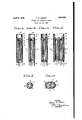
- Fig. l is an enlarged sectional elevation of one embodiment of my improved cathode.
- K Fig. 2 is an enlarged sectional elevation of an alternative formof my cathode.
- Fig. 3 is a cross-section taken on the line 33 of Fig. 2.
- Fig. 4 is an enlarged sectional elevation of bring out the structural features of my in- "1.
- Fig. 1 illustrates an embodiment of my idea in which the heater wire 1, composed. of tungsten or other material which is rendered incandescent by the passage of electric current therethrough, is co-axially disposed within preferably a nickel cylinder or tube 3, the upper extremity of which is tapered to a point 2 as shown.
- the heater wire 1 is welded or otherwise conductively connected to the tapered point 2 and a terminal 4 is provided for the tube.
- the tube 3 functions as a portion of the return circuit for the heating current and as it completely encircles the heater wire 1, obviously there will exist outside of the tube no mag,- netic stray field resulting from the passage of the alternating heating current there through.
- a cylinder 6 of refractory mate' rial such as porcelain maintains the heater wire 1 in co-axial alignment with the tube 3.
- a metallic cylinder 8, provided prefer; ably with a closed top 14:, is co-axially maintained with respect to the heater wire 1 and tube 3 by means of the cylinder of the refractory material 7.
- Cylinder 8 is provided with a coating of electron emitting substance or substances such as strontium or barium oxide or a mixture thereof and constitutes the element from which electrons are emitted can! through the agency of the heat developed by the ineandescence of the heater wire 1.
- Figs. 2 and 3 I have shown another embodiment of my idea in which the refrac tory cylinder 6 is omitted and the heater wire is maintained in co-axial relationship with the return circuit tube 3 by tension or by the employment of a heater wire of proper dimensions to exhibit the necessary rigidity to accomplish the purpose.
- the cylinder 8 carries thereon electron emitting substances 9 and is separated from the tube 3 by the cylinder 7 of refractory material.
- a connection 5 to the cylinder 8 is provided for extension through the press of the ther mionic tube that electrical connectionmay be made with the active portion of the cathode.
- the length of the present day heater is governed by the alternating current voltages used and the physical constants of the tungsten heater wire and it is not possible to use the standard heater wire length with my coaxial cylinder construction.
- Heater wire 1 is connected to return co-axial cylinder 3, the lower extremity of which is connected through conductor 10 with the lower extremity of cylinder 12 to the top of which is attached heater wire 11.
- the twin heaters thus formed are surrounded by refractory material 17 which carries a metallic sleeve 28 hearing electron emitting substances 19 thereon and a connection wire 15 attached thereto.
- my improved cathode may be adapted to present day Voltages in keeping with standard heater wire lengths.
- the embodi- Vment of my invention just described may be utilized in standard thermionic tubes without requiring any change of voltage in the heater supply to permit the construction of a thermionc tube which may be used in standardized circuits and with standardized equip ment.
- my improved cathode reduces magnetic strays from the alternating heating current to zero as no magnetic stray can exist outside of the enclosing metallic tube 3 which functions as the return circuit for all of the heating current traversing the heating wire 1 and that thus I have produced a cathode by which thermionic tubes may he constructed which exhibit no hum due to magnetic strays from the heating current.
- a cathode comprising, a pair of metal lic cylinders conductively connected to each other, a heater wire co-axially disposed within each of said cylinders and conductively connected thereto and an electron emitting element disposed adjacent to said cylinders.
- a cathode comprising, a plurality of cylindrical conductors conductively connected to each other at one of the extremities thereof, a heating element co-axially disposed within each of said conductors and conductively connected thereto and an electron emitting element enclosing said cylindrical conductors.
- A. cathode comprising, a pair of hollow cylindrical conductors one extremity of each of which is closed and the other extremities of which are conductively connected to each other, a heating element C o-axially disposed within each of said conductors and conductively connected to the closed extremities thereof and an electron emitting element dis- I ity and conductively connected to each other i at the other extremities thereof,'a heating element co-axially disposed Within each of said conductors and conductively connected respectively to the closed extremities thereof and a metallic member bearing electron emitting substances surrounding said cylindrical conductors.
Landscapes
- Microwave Tubes (AREA)
Description
April 5 1932. H. w PARKER CATHODE FOR THERMIONIC TUBES Filed July 25, 1930 Fis- 4:
EEG--5 Hrs--1 EEG-.2
uwwg i1llw Illl nuiggggi g g xi gi W222 EEG-.5 EEG- 5 INVENTOR Hg l'zry W Parker. @Z
.RNEY' Patented Apr. 1932 UNETED STAT HENRY W. PARKER, OE TORONTO, ONTARIO, CANADA, ASSIGNOR TO ROGERS RADIO C TUBES, LIlVIITED, OF TORONTO, ONTARIO, CANADA, A CORPORATION OF ONTARIO GATHODE FOR THEBMIONIO TUBES Application filed m 25, 1930/ Serial No. 470,625.
My invention relates to cathodes for electron discharge devices such as thermionic tubes and pertains more specifically to that type of cathode termed equi-potential and 5 employing separate heating and emitting members.
An object of my invention consists in providing a cathode of the indirectly heated type in which the magnetic field in the proximity of the cathode produced by the alternating heating current is reduced to zero.
Another object contemplates providing a cathode through the use of which an alternating current heated thermionic tube may be constructed which exhibits no disturbing hum due to modulation of the space current of the tube by magnetic strays from the heating current.
, A still further object consists in providing a cathode which will permit of the construc tion of thermionic tubes having a higher quality of output.
I accomplish all these and other desirable I features which will be hereinafter pointed out and discussed by reducing the magnetic field in the proximity of the heating element to exactly zero by employing a heater in the form of a heating wire maintained co-axially within a conducting cylinder which likewise functions as a portion of the return circuit for the current traversing the heater wire.
Many attempts have hitherto been made to reduce the hum in thermionic tubes employing indirectly heated cathodes and up to the present time the most successful type of hum eliminating cathode utilizes a heater. consisting of a wire shaped to form a loop. This so-called hairpin type of heater eliminates a certain portion of the stray magnetic field produced by the alternating heating current, but does not reduce such stray to zero.
With my improved form of cathode, I achieve complete and absolute elimination of magnetic strays from the alternating heating current and thus through the use of such cathode thermionic tubes exhibiting a hum-free output of higher quality may be constructed.
In the drawings accompanying and forming a part of this specification, in which like numerals designate corresponding parts throughout Fig. l is an enlarged sectional elevation of one embodiment of my improved cathode. K Fig. 2 is an enlarged sectional elevation of an alternative formof my cathode.
Fig. 3 is a cross-section taken on the line 33 of Fig. 2.
Fig. 4 is an enlarged sectional elevation of bring out the structural features of my in- "1.
vention:
Fig. 1 illustrates an embodiment of my idea in which the heater wire 1, composed. of tungsten or other material which is rendered incandescent by the passage of electric current therethrough, is co-axially disposed within preferably a nickel cylinder or tube 3, the upper extremity of which is tapered to a point 2 as shown. The heater wire 1 is welded or otherwise conductively connected to the tapered point 2 and a terminal 4 is provided for the tube. The tube 3 functions as a portion of the return circuit for the heating current and as it completely encircles the heater wire 1, obviously there will exist outside of the tube no mag,- netic stray field resulting from the passage of the alternating heating current there through. A cylinder 6 of refractory mate' rial such as porcelain maintains the heater wire 1 in co-axial alignment with the tube 3. A metallic cylinder 8, provided prefer; ably with a closed top 14:, is co-axially maintained with respect to the heater wire 1 and tube 3 by means of the cylinder of the refractory material 7. Cylinder 8 is provided with a coating of electron emitting substance or substances such as strontium or barium oxide or a mixture thereof and constitutes the element from which electrons are emitted can! through the agency of the heat developed by the ineandescence of the heater wire 1.
In Figs. 2 and 3 I have shown another embodiment of my idea in which the refrac tory cylinder 6 is omitted and the heater wire is maintained in co-axial relationship with the return circuit tube 3 by tension or by the employment of a heater wire of proper dimensions to exhibit the necessary rigidity to accomplish the purpose. The cylinder 8 carries thereon electron emitting substances 9 and is separated from the tube 3 by the cylinder 7 of refractory material. A connection 5 to the cylinder 8 is provided for extension through the press of the ther mionic tube that electrical connectionmay be made with the active portion of the cathode.
Referring to Fig. 4, I have illustrated a still further embodiment of my idea wherein the electron emitting substance or substances are carried by a perforated cylinder 18. The use of t e perforated cylinder is not necessary but constitutes an embodiment whereby heat transfer from the heater wire 1 to the electron emitting substances 9 is facilitated.
The length of the present day heater is governed by the alternating current voltages used and the physical constants of the tungsten heater wire and it is not possible to use the standard heater wire length with my coaxial cylinder construction. In order to obtain the same length of heater wire as is now common in standard thermionic tubes, it is necessary in my construction to use two heaters connected in series as shown in Fig. 5. Heater wire 1 is connected to return co-axial cylinder 3, the lower extremity of which is connected through conductor 10 with the lower extremity of cylinder 12 to the top of which is attached heater wire 11. The twin heaters thus formed are surrounded by refractory material 17 which carries a metallic sleeve 28 hearing electron emitting substances 19 thereon and a connection wire 15 attached thereto.
With this type of construction, my improved cathode may be adapted to present day Voltages in keeping with standard heater wire lengths. In other words, the embodi- Vment of my invention just described may be utilized in standard thermionic tubes without requiring any change of voltage in the heater supply to permit the construction of a thermionc tube which may be used in standardized circuits and with standardized equip ment.
It will be noted that my improved cathode reduces magnetic strays from the alternating heating current to zero as no magnetic stray can exist outside of the enclosing metallic tube 3 which functions as the return circuit for all of the heating current traversing the heating wire 1 and that thus I have produced a cathode by which thermionic tubes may he constructed which exhibit no hum due to magnetic strays from the heating current.
As noted hereinbefore, I have purposely exaggerated the diameters of the return tubes and the electron emissive cylinders in order that the construction of my cathode may be more clearly shown. Obviously, the diameters of the elements of my cathode must be so proportioned that the proper activation temperature may be obtained, butsuch requirement will be readily understood by anyone skilled in the art.
Having thus completely described my invention by the illustration and description of several embodiments thereof, what Iclaim as new and desire to secure by Letters Patent of the United States is as follows: 7
1. A cathode comprising, a pair of metal lic cylinders conductively connected to each other, a heater wire co-axially disposed within each of said cylinders and conductively connected thereto and an electron emitting element disposed adjacent to said cylinders.
2. A cathode comprising, a plurality of cylindrical conductors conductively connected to each other at one of the extremities thereof, a heating element co-axially disposed within each of said conductors and conductively connected thereto and an electron emitting element enclosing said cylindrical conductors. r
8. A. cathode comprising, a pair of hollow cylindrical conductors one extremity of each of which is closed and the other extremities of which are conductively connected to each other, a heating element C o-axially disposed within each of said conductors and conductively connected to the closed extremities thereof and an electron emitting element dis- I ity and conductively connected to each other i at the other extremities thereof,'a heating element co-axially disposed Within each of said conductors and conductively connected respectively to the closed extremities thereof and a metallic member bearing electron emitting substances surrounding said cylindrical conductors.
HENRY w. PARKER,
Priority Applications (1)
| Application Number | Priority Date | Filing Date | Title |
|---|---|---|---|
| US470625A US1852023A (en) | 1930-07-25 | 1930-07-25 | Cathode for thermionic tubes |
Applications Claiming Priority (1)
| Application Number | Priority Date | Filing Date | Title |
|---|---|---|---|
| US470625A US1852023A (en) | 1930-07-25 | 1930-07-25 | Cathode for thermionic tubes |
Publications (1)
| Publication Number | Publication Date |
|---|---|
| US1852023A true US1852023A (en) | 1932-04-05 |
Family
ID=23868345
Family Applications (1)
| Application Number | Title | Priority Date | Filing Date |
|---|---|---|---|
| US470625A Expired - Lifetime US1852023A (en) | 1930-07-25 | 1930-07-25 | Cathode for thermionic tubes |
Country Status (1)
| Country | Link |
|---|---|
| US (1) | US1852023A (en) |
Cited By (2)
| Publication number | Priority date | Publication date | Assignee | Title |
|---|---|---|---|---|
| US2750526A (en) * | 1946-05-03 | 1956-06-12 | Kenneth J Germeshausen | Indirectly heated cathode |
| US10741351B1 (en) | 2019-08-01 | 2020-08-11 | Lockheed Martin Corporation | Multi-apertured conduction heater |
-
1930
- 1930-07-25 US US470625A patent/US1852023A/en not_active Expired - Lifetime
Cited By (3)
| Publication number | Priority date | Publication date | Assignee | Title |
|---|---|---|---|---|
| US2750526A (en) * | 1946-05-03 | 1956-06-12 | Kenneth J Germeshausen | Indirectly heated cathode |
| US10741351B1 (en) | 2019-08-01 | 2020-08-11 | Lockheed Martin Corporation | Multi-apertured conduction heater |
| KR20220028182A (en) * | 2019-08-01 | 2022-03-08 | 록히드 마틴 코포레이션 | Multi-Aperture Conduction Heater |
Similar Documents
| Publication | Publication Date | Title |
|---|---|---|
| US2358542A (en) | Currentless grid tube | |
| US2201720A (en) | Thermionic cathode structure | |
| US2044369A (en) | Electron discharge device | |
| US2135941A (en) | Electrode structure | |
| US1852023A (en) | Cathode for thermionic tubes | |
| US1866715A (en) | Assembly of elements in electron devices | |
| US2554078A (en) | Electron discharge device and locking means therefor | |
| US2081415A (en) | Electron emitter | |
| US1917991A (en) | Vacuum tube filament structure | |
| US1909051A (en) | Thermionic vacuum tube | |
| US2087327A (en) | Electron discharge device | |
| US2067529A (en) | Electron discharge device | |
| GB502976A (en) | Electronic discharge devices of the electron multiplier type | |
| US2015327A (en) | Electron discharge device | |
| US1932077A (en) | Space current device | |
| US1929931A (en) | Cathode for electron discharge devices | |
| US2201880A (en) | Electron discharge device | |
| US2117842A (en) | Electrode | |
| US1828203A (en) | Electron discharge tube | |
| US1878089A (en) | Electron emitting device | |
| US1997196A (en) | Electron discharge device | |
| US1492000A (en) | Thermionic device for wireless telegraphy and telephony | |
| US1941107A (en) | Thermionic tube construction | |
| US2007933A (en) | Lamp construction | |
| US2522419A (en) | Filament structure |