US1852020A - Electrode for luminous tubes - Google Patents
Electrode for luminous tubes Download PDFInfo
- Publication number
- US1852020A US1852020A US326480A US32648028A US1852020A US 1852020 A US1852020 A US 1852020A US 326480 A US326480 A US 326480A US 32648028 A US32648028 A US 32648028A US 1852020 A US1852020 A US 1852020A
- Authority
- US
- United States
- Prior art keywords
- electrode
- tube
- luminous tubes
- tubes
- cylinder
- Prior art date
- Legal status (The legal status is an assumption and is not a legal conclusion. Google has not performed a legal analysis and makes no representation as to the accuracy of the status listed.)
- Expired - Lifetime
Links
- 239000007789 gas Substances 0.000 description 8
- XEEYBQQBJWHFJM-UHFFFAOYSA-N Iron Chemical compound [Fe] XEEYBQQBJWHFJM-UHFFFAOYSA-N 0.000 description 5
- 239000000463 material Substances 0.000 description 5
- PXHVJJICTQNCMI-UHFFFAOYSA-N Nickel Chemical compound [Ni] PXHVJJICTQNCMI-UHFFFAOYSA-N 0.000 description 4
- 239000004020 conductor Substances 0.000 description 3
- 229910052751 metal Inorganic materials 0.000 description 3
- 239000002184 metal Substances 0.000 description 3
- 229910052754 neon Inorganic materials 0.000 description 3
- GKAOGPIIYCISHV-UHFFFAOYSA-N neon atom Chemical compound [Ne] GKAOGPIIYCISHV-UHFFFAOYSA-N 0.000 description 3
- XKRFYHLGVUSROY-UHFFFAOYSA-N Argon Chemical compound [Ar] XKRFYHLGVUSROY-UHFFFAOYSA-N 0.000 description 2
- 235000009854 Cucurbita moschata Nutrition 0.000 description 2
- 240000001980 Cucurbita pepo Species 0.000 description 2
- 235000009852 Cucurbita pepo Nutrition 0.000 description 2
- 229910052782 aluminium Inorganic materials 0.000 description 2
- XAGFODPZIPBFFR-UHFFFAOYSA-N aluminium Chemical compound [Al] XAGFODPZIPBFFR-UHFFFAOYSA-N 0.000 description 2
- 229910052734 helium Inorganic materials 0.000 description 2
- 239000001307 helium Substances 0.000 description 2
- SWQJXJOGLNCZEY-UHFFFAOYSA-N helium atom Chemical compound [He] SWQJXJOGLNCZEY-UHFFFAOYSA-N 0.000 description 2
- 229910052742 iron Inorganic materials 0.000 description 2
- QSHDDOUJBYECFT-UHFFFAOYSA-N mercury Chemical compound [Hg] QSHDDOUJBYECFT-UHFFFAOYSA-N 0.000 description 2
- 239000000203 mixture Substances 0.000 description 2
- 229910052759 nickel Inorganic materials 0.000 description 2
- 238000004544 sputter deposition Methods 0.000 description 2
- 235000020354 squash Nutrition 0.000 description 2
- ZSLUVFAKFWKJRC-IGMARMGPSA-N 232Th Chemical compound [232Th] ZSLUVFAKFWKJRC-IGMARMGPSA-N 0.000 description 1
- 229910052684 Cerium Inorganic materials 0.000 description 1
- RYGMFSIKBFXOCR-UHFFFAOYSA-N Copper Chemical compound [Cu] RYGMFSIKBFXOCR-UHFFFAOYSA-N 0.000 description 1
- LFQSCWFLJHTTHZ-UHFFFAOYSA-N Ethanol Chemical compound CCO LFQSCWFLJHTTHZ-UHFFFAOYSA-N 0.000 description 1
- 229910052776 Thorium Inorganic materials 0.000 description 1
- 239000004421 Wonderlite Substances 0.000 description 1
- 229910052786 argon Inorganic materials 0.000 description 1
- -1 cerium Chemical class 0.000 description 1
- GWXLDORMOJMVQZ-UHFFFAOYSA-N cerium Chemical compound [Ce] GWXLDORMOJMVQZ-UHFFFAOYSA-N 0.000 description 1
- 229910052802 copper Inorganic materials 0.000 description 1
- 239000010949 copper Substances 0.000 description 1
- 238000010586 diagram Methods 0.000 description 1
- 239000011521 glass Substances 0.000 description 1
- 229910052753 mercury Inorganic materials 0.000 description 1
- 150000002739 metals Chemical class 0.000 description 1
- 229910052756 noble gas Inorganic materials 0.000 description 1
- 239000003973 paint Substances 0.000 description 1
- 239000002245 particle Substances 0.000 description 1
- 229910052761 rare earth metal Inorganic materials 0.000 description 1
- 150000002910 rare earth metals Chemical class 0.000 description 1
- 229910052712 strontium Inorganic materials 0.000 description 1
- CIOAGBVUUVVLOB-UHFFFAOYSA-N strontium atom Chemical compound [Sr] CIOAGBVUUVVLOB-UHFFFAOYSA-N 0.000 description 1
Images
Classifications
-
- H—ELECTRICITY
- H01—ELECTRIC ELEMENTS
- H01J—ELECTRIC DISCHARGE TUBES OR DISCHARGE LAMPS
- H01J17/00—Gas-filled discharge tubes with solid cathode
- H01J17/02—Details
- H01J17/04—Electrodes; Screens
- H01J17/06—Cathodes
- H01J17/066—Cold cathodes
-
- H—ELECTRICITY
- H01—ELECTRIC ELEMENTS
- H01J—ELECTRIC DISCHARGE TUBES OR DISCHARGE LAMPS
- H01J2893/00—Discharge tubes and lamps
- H01J2893/0064—Tubes with cold main electrodes (including cold cathodes)
- H01J2893/0065—Electrode systems
- H01J2893/0066—Construction, material, support, protection and temperature regulation of electrodes; Electrode cups
Definitions
- ELECTRODE FOR LUMINOUS TUBES This invention relates to luminous tubes, such as are caused to emit light when excited by an electric potential difference applied across points in the tube by the'aid of electrodes.
- Such tubes are now well known. They usually include a filling of a noble gas of the rare monatomic series (helium, neon, argon, etc.) or combinations of these gases, or with other gases outside of this group, such as mercury vapor.
- the tubes are usually filled to a pressure of about 6 mm. of mercury.
- My invention possesses many other advantages, and has other objects which may be made more easily apparent from a cons deration of one embodiment of my invention.
- I have shown a form in the drawings accompanying and forming part of the present specification. I shall now proceed to describe this form in detail, which illustrates the general principles of my invention; but it is to be understood that this detailed description is not to be taken n a l miting sense, since the scope'of my invention is best defined by the appended claims.
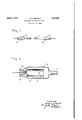
- Figure 1 is a diagram of a luminous tube, shown of indefinite length, in which my new electrodes can be incorporated;
- Fig. 2 is an enlarged sectional view of one end of the tube and of the electrode therein d1sposed.
- a tube 11 of indefinite length which can be made from glass or other translucent material.
- This tube can be filled with any gas or mixture of gases that can be ionized to a luminescent stage; for example, helium or neon or mixtures thereof.
- the tube of course must be sealed.
- the electrode structure is best disclosed in Fig. 2. It includes a hollow inner cylinder 16 of good conducting material, so as to provide a. low electrode drop on its inner surface. Encompassing this cylinder, 16 is an outer cylinder 17 of poorer conductivity, to provide a large electrode drop on the outside surface.
- the two cylinders 16, 17 can be joined together in any appropriate manner.
- the electrode structure 18 can be appropriately supported, as by the aid of a press or squash 18.
- lVires or rods 19 are sealed in the squash and extend out of the tube to form a terminal. Inside of the tube, they can be fastened to the inner surface of the electrode.
- inner cylinder 16 can be aluminum, and the outer cylinder 17 can be iron or nickel.
- inner cylinder 16 can be aluminum, and the outer cylinder 17 can be iron or nickel.
- Another example is to make the inner cylinder out of any well known 5 conducting metal such as nickel, iron, or copper, and to coat this with a refractory oxide, such as of some of the rare earth metals, including cerium, as well as of strontium and thorium, which oxides have the property of 1 becoming conductors when heated and have. an electrode drop higher than most of the metals. If these oxides are powdered, they 7 can be mixed with alcohol and applied as a paint. However, in all forms, the outer layer 17 has conducting properties but with a relatively larger electrode drop.
Landscapes
- Discharge Lamp (AREA)
Description
April 5, 1932. H. E. 'METCALF 1,352,020
ELECTRODE FOR LUMINOUS TUBES Filed Dec. 17, 1928 Tic Z 1 IIIIII'IIIIIII'I'I lI/1I'l lIr/ I I III'I INVENTOR.
ATTORNEY Patented Apr. ;5, 1932 "UNITED STATES PATENT OFFICE- HERBERT E. METCALF, OF OAKLAND, CALIFORNIA, ASSIGNOR, IBY MESNE ASSIGNMENTS,
TO WONDERLITE NEON PRODUCTS CO. LTD.
ELECTRODE FOR LUMINOUS TUBES This invention relates to luminous tubes, such as are caused to emit light when excited by an electric potential difference applied across points in the tube by the'aid of electrodes.
Such tubes are now well known. They usually include a filling of a noble gas of the rare monatomic series (helium, neon, argon, etc.) or combinations of these gases, or with other gases outside of this group, such as mercury vapor. The tubes are usually filled to a pressure of about 6 mm. of mercury. It
' of the tube thus ultimately take up by occlusion a large part of the gaseous filling.
It is one of the objects of my invention to prevent this sputtering action, and especially by appropriate choice of electrode structure. I find that I can confine the activity of the electrode wholly to an interior surface (such as the interior of a hollow cylindrical electrode), by making the electrode exterior of material that is a poorer conductor than the interior. Under such circumstances, although the exterior layer is nevertheless conductive, yet the gas molecules prefer contact with the interior, more conductive surface, to the substantially entire neglect of the exterior surface. Therefore, whatever sputtering takes place is confined to the inside. of the electrode. Although the sputtered particles carry gases from one part of the interior surface to another, yet due to the heat conditions, these gases are not'permanently occluded, and the tube has a long life. Accordingly, it is another object of my in vention to provide an electrode built up of a plurality of layers of material having different conductivities, the lower conductivit material being on the exterior side.
My invention possesses many other advantages, and has other objects which may be made more easily apparent from a cons deration of one embodiment of my invention. For this purpose I have shown a form in the drawings accompanying and forming part of the present specification. I shall now proceed to describe this form in detail, which illustrates the general principles of my invention; but it is to be understood that this detailed description is not to be taken n a l miting sense, since the scope'of my invention is best defined by the appended claims.
Referring to the drawings:
Figure 1 is a diagram of a luminous tube, shown of indefinite length, in which my new electrodes can be incorporated; and
Fig. 2 is an enlarged sectional view of one end of the tube and of the electrode therein d1sposed.' In Fig. 1, there is indicated a tube 11 of indefinite length, which can be made from glass or other translucent material. This tube can be filled with any gas or mixture of gases that can be ionized to a luminescent stage; for example, helium or neon or mixtures thereof. The tube of course must be sealed. In order to impress an electromotive force on the column of gas in tube 11, there are shown the electrodes 12, 13, located in the enlarged ends 14, 15 of tube 11.
The electrode structure is best disclosed in Fig. 2. It includes a hollow inner cylinder 16 of good conducting material, so as to provide a. low electrode drop on its inner surface. Encompassing this cylinder, 16 is an outer cylinder 17 of poorer conductivity, to provide a large electrode drop on the outside surface. The two cylinders 16, 17 can be joined together in any appropriate manner.
The electrode structure 18 can be appropriately supported, as by the aid of a press or squash 18. lVires or rods 19 are sealed in the squash and extend out of the tube to form a terminal. Inside of the tube, they can be fastened to the inner surface of the electrode.
As an example of materials that can be used for members 16 and 17, inner cylinder 16 can be aluminum, and the outer cylinder 17 can be iron or nickel. Another example is to make the inner cylinder out of any well known 5 conducting metal such as nickel, iron, or copper, and to coat this with a refractory oxide, such as of some of the rare earth metals, including cerium, as well as of strontium and thorium, which oxides have the property of 1 becoming conductors when heated and have. an electrode drop higher than most of the metals. If these oxides are powdered, they 7 can be mixed with alcohol and applied as a paint. However, in all forms, the outer layer 17 has conducting properties but with a relatively larger electrode drop.
I claim: I 1. In an electrode structure for luminescent tubes, an inner metallic cylinder, and a con- 20 ducting cylinder superposed over the inner cylinder and having an external surface with 3 larger electrode drop than the inner cylin- 2. In an electrode structure for luminescent tubes, an inner cylinder of aluminum and an outer cylinder encompassing and supported on said inner cylinder, made from metal of the iron group. In testlmony whereof I have hereunto set 50 my hand.
HERBERT E. METOALF.
Priority Applications (1)
| Application Number | Priority Date | Filing Date | Title |
|---|---|---|---|
| US326480A US1852020A (en) | 1928-12-17 | 1928-12-17 | Electrode for luminous tubes |
Applications Claiming Priority (1)
| Application Number | Priority Date | Filing Date | Title |
|---|---|---|---|
| US326480A US1852020A (en) | 1928-12-17 | 1928-12-17 | Electrode for luminous tubes |
Publications (1)
| Publication Number | Publication Date |
|---|---|
| US1852020A true US1852020A (en) | 1932-04-05 |
Family
ID=23272388
Family Applications (1)
| Application Number | Title | Priority Date | Filing Date |
|---|---|---|---|
| US326480A Expired - Lifetime US1852020A (en) | 1928-12-17 | 1928-12-17 | Electrode for luminous tubes |
Country Status (1)
| Country | Link |
|---|---|
| US (1) | US1852020A (en) |
Cited By (14)
| Publication number | Priority date | Publication date | Assignee | Title |
|---|---|---|---|---|
| US2459789A (en) * | 1946-08-21 | 1949-01-25 | Superior Tube Co | Electrode construction for neon signs |
| US2486497A (en) * | 1946-04-23 | 1949-11-01 | George C Salneu | Termination for electric discharge lamps |
| US2496374A (en) * | 1943-11-24 | 1950-02-07 | Boucher And Keiser Company | Tubular electric lamp |
| US2508114A (en) * | 1947-12-05 | 1950-05-16 | Gen Electric | Tantalum electrode for electric discharge devices |
| US2607901A (en) * | 1946-12-31 | 1952-08-19 | Bell Telephone Labor Inc | Electronic discharge device |
| US2843785A (en) * | 1954-04-19 | 1958-07-15 | Sylvania Electric Prod | Thermal insulation for cathode |
| US2874325A (en) * | 1952-02-05 | 1959-02-17 | Ets Claude Paz & Silva | Electrode for electric discharge apparatus |
| US2886737A (en) * | 1949-11-11 | 1959-05-12 | Fruengel Frank | Quick-responsive spark gap device |
| US2891184A (en) * | 1956-01-31 | 1959-06-16 | Burroughs Corp | Glow tube cathode |
| US2913298A (en) * | 1956-12-19 | 1959-11-17 | Pat & Visseaux Claude | Cold and hollow electrode |
| US2943226A (en) * | 1956-01-31 | 1960-06-28 | Ets Claude Paz & Silva | Cold and hollow electrode |
| US3179832A (en) * | 1960-01-12 | 1965-04-20 | Field Emission Corp | Temperature enhanced field emission x-ray tube |
| US3530559A (en) * | 1968-03-12 | 1970-09-29 | Sylvania Electric Prod | Anode electrode fabrication |
| FR2174090A1 (en) * | 1972-02-28 | 1973-10-12 | Matsushita Electric Industrial Co Ltd |
-
1928
- 1928-12-17 US US326480A patent/US1852020A/en not_active Expired - Lifetime
Cited By (14)
| Publication number | Priority date | Publication date | Assignee | Title |
|---|---|---|---|---|
| US2496374A (en) * | 1943-11-24 | 1950-02-07 | Boucher And Keiser Company | Tubular electric lamp |
| US2486497A (en) * | 1946-04-23 | 1949-11-01 | George C Salneu | Termination for electric discharge lamps |
| US2459789A (en) * | 1946-08-21 | 1949-01-25 | Superior Tube Co | Electrode construction for neon signs |
| US2607901A (en) * | 1946-12-31 | 1952-08-19 | Bell Telephone Labor Inc | Electronic discharge device |
| US2508114A (en) * | 1947-12-05 | 1950-05-16 | Gen Electric | Tantalum electrode for electric discharge devices |
| US2886737A (en) * | 1949-11-11 | 1959-05-12 | Fruengel Frank | Quick-responsive spark gap device |
| US2874325A (en) * | 1952-02-05 | 1959-02-17 | Ets Claude Paz & Silva | Electrode for electric discharge apparatus |
| US2843785A (en) * | 1954-04-19 | 1958-07-15 | Sylvania Electric Prod | Thermal insulation for cathode |
| US2891184A (en) * | 1956-01-31 | 1959-06-16 | Burroughs Corp | Glow tube cathode |
| US2943226A (en) * | 1956-01-31 | 1960-06-28 | Ets Claude Paz & Silva | Cold and hollow electrode |
| US2913298A (en) * | 1956-12-19 | 1959-11-17 | Pat & Visseaux Claude | Cold and hollow electrode |
| US3179832A (en) * | 1960-01-12 | 1965-04-20 | Field Emission Corp | Temperature enhanced field emission x-ray tube |
| US3530559A (en) * | 1968-03-12 | 1970-09-29 | Sylvania Electric Prod | Anode electrode fabrication |
| FR2174090A1 (en) * | 1972-02-28 | 1973-10-12 | Matsushita Electric Industrial Co Ltd |
Similar Documents
| Publication | Publication Date | Title |
|---|---|---|
| US1852020A (en) | Electrode for luminous tubes | |
| GB1219446A (en) | Gaseous glow indicator tube | |
| US4723093A (en) | Gas discharge device | |
| US3264511A (en) | Glow discharge device | |
| US2053879A (en) | Discharge tube | |
| US2683836A (en) | Electric discharge device construction | |
| US1915019A (en) | Gaseous electric discharge device | |
| US2056613A (en) | Electric gaseous discharge device | |
| US1968839A (en) | Low voltage discharge tube | |
| US1935423A (en) | Electric discharge device | |
| US2076286A (en) | Electric gaseous discharge device | |
| US2096236A (en) | Electrical discharge device | |
| US2212881A (en) | Electric gaseous discharge device | |
| US2709767A (en) | Electric discharge device | |
| US2030715A (en) | Gaseous electric discharge lamp device | |
| US2452626A (en) | Electron emitter | |
| TW580722B (en) | Low-pressure gas discharge lamp | |
| US2164183A (en) | Electric lamp | |
| US2377164A (en) | Electrical assembly | |
| US2000395A (en) | Glowlamp | |
| US3258629A (en) | Cold cathode display device with fluorescent indicia anodes | |
| US1872302A (en) | Glow discharge device | |
| US3819975A (en) | Multi-digit glow indicator tube | |
| US2890364A (en) | Electric discharge tube | |
| US2367579A (en) | Gaseous conduction discharge device |