US1852019A - Staple forming and inserting machine - Google Patents
Staple forming and inserting machine Download PDFInfo
- Publication number
- US1852019A US1852019A US335852A US33585229A US1852019A US 1852019 A US1852019 A US 1852019A US 335852 A US335852 A US 335852A US 33585229 A US33585229 A US 33585229A US 1852019 A US1852019 A US 1852019A
- Authority
- US
- United States
- Prior art keywords
- lever
- wire
- machine
- staples
- staple
- Prior art date
- Legal status (The legal status is an assumption and is not a legal conclusion. Google has not performed a legal analysis and makes no representation as to the accuracy of the status listed.)
- Expired - Lifetime
Links
- 238000009740 moulding (composite fabrication) Methods 0.000 description 23
- 239000011435 rock Substances 0.000 description 6
- 230000015572 biosynthetic process Effects 0.000 description 3
- 239000010985 leather Substances 0.000 description 1
- 238000004519 manufacturing process Methods 0.000 description 1
- 238000000034 method Methods 0.000 description 1
- 235000002020 sage Nutrition 0.000 description 1
Images


Classifications
-
- A—HUMAN NECESSITIES
- A43—FOOTWEAR
- A43D—MACHINES, TOOLS, EQUIPMENT OR METHODS FOR MANUFACTURING OR REPAIRING FOOTWEAR
- A43D69/00—Shoe-nailing machines
- A43D69/04—Shoe-nailing machines with apparatus for separating the nails from a wire or from a strip of metal or other material
Definitions
- This invention relates-to stapling machines
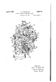
- FIG. 1 is a side elevation of the head of V a stapling machine embodying the present invention and illustrating its use in the attachment of a sole member to a shoe by allaround stapling;
- Fig. 2 illustrates a McKay shoewhich has been repaired by the attachment of awnewsole byall-around stapling
- v Fig. 3 is a front elevationof the head of" the machine in -"Fig. 1;
- Fig. 4 is a sectional view'on the line IV'IV of'Fig. 3, showingthe throatmember or nozzl'e of the machine in cross-section, and showing'also the IBhLtlOIl'OfL gage toythe nozzle and the relation of the-bars of the staples to the edge of the-sole ofthe shoe'inwhich theyare inserted;
- Fig. 5 is a perspective view,'partly in cross section, showing the wire feeding means of' themachine and partof the adjusting mechanism therefor; and I Fig. 6 is a perspective'view of the" head of the machine.
- the head 10 of the illustrated machine may. be supported in any suitable manner as by a column 12 the upper portion of which is shown in Fig. 1;
- a cam shaft 14 is mountedin suitable bearingscarriedby'or formed in, the head 10 and is rotated in anysuitable; fashionv
- the illustrated machine is provided with clutch mechanism 16 mounted upon the shaft 14 and controlled by a trea-dle' connected to a treadle rod 18' sothat the shaft 14' may be driven by or operatively'discona nested from a belt-pulley :20.
- lifting cam 26 (Figs. 1, 3 and 6) in co-operating relation to a lifting block 28 fast upon a driver bar 30 mounted for vertical reciprocation in ways formed in the head of the machine and carrying at its lower end a driver 32.
- the upper end of the driver bar 30 is Connected by a link 34 to a lever 36 fulcrumed at 38 to an upstanding bracket 40 carried by the head 10 of th'einachine and urged in a blockwise direction as viewed in Fig. 1 by a stiff coil spring 42 one end of which bears against the lever 36 and the other end of which is adjus'tably secured to the bracket 40.
- a bumper 44 secured to the driver bar 30 is provided with a series of leather washers 46 arranged to strike a surface formed upon the top to the head 10, therebylimiting the downward stroke of the driver 32 and the driver bar 30 and cushioning the blow.
- v v I The machine isprovided with a nozzle or throat member 48 having a driver passage49 in line with the driver 32. This'driver passage 49 iselongated in cross-section (as shown in Fig.4), its greater dimension extending toward and from an operator standing in his normal position in front of the machine.
- an inside former 72 (Figs, 1 and 3) carried at the forward end of a stem 7 4 slidably mounted in the head of themachine and provided at its right-hand end, as viewed in Fig. 3, with a pin 76 extending into a slot formed in the lower end of an approximately vertical lever 7 8 fulcrumed upon the shaft 62 for rocking movement independently thereof.
- the lever 7 8 At its upper end the lever 7 8 is provided with a cam roll 80 engaging a surface cam 82 (Fig. 1) fast upon the cam shaft 14 and yieldingly held in engagement therewith by a spring 84.
- the wire W from which the staples inserted by the machine are formed is carried upon 0 a reel 86 carried by a bracket 88 secured to the head 10 of the machine from which it passes downwardly through holes 100 formed in the head of the machine to a pair of feed rolls 102, 104 by which it is fed, as more fully hereinafter described, toward and past a stationary knife 106 and a movable knife 108 into staple forming position above the inside former 7 2 and below the outside formers 50.
- a staple length'of the wire W has been fed to this position the knives 106, 108 are operated, as more fully hereinafter described, to sever a piece of wire, whereupon the outside formers 50 descend, wiping the wire into staple form about the insideformer 72.
- the severed portion of the wire W, and consequently the bar of the staple formed therefrom, is positioned in a direction extending toward and from the operator. Accordingly, when, after the withdrawal of the inside former 72, the staple is drivendownwardly and into a shoe S presented to the nozzle 48 for all-around stapling with the edge of its sole110 in engagement with an edge gage 112, the bar of the staple will extend substantially at right angles to the edge of the sole-as shown in Figs. 1, 2 and 4.
- the feed roll 102 anda pinion 114 secured thereto and concentric therewith are carried by a slide member 116 provided with a dovetailed slot 117 engaged by a complemental dovetailed rib 118 secured to the head 10 of the machine and extending in a forwardly and rearwardly direction.
- F ulcrumed at 120 to the slide member 116 is a lever 122 formed at its forward end with a gear segment 128 and provided at its rear end with a slot in which is positioned a pivot pin 130 carried by the lower end of a rod 132 mounted for vertical sliding movement in a guideway formed in a lug 134 extending rearwardly from the slide 116.
- the rod 132 is adjustably connected to a bell crank lever 136 through a block 138slidably mounted in a slot 140 formed near the end of an arm A of the'bell crank lever 136 which extends substantially parallel to thelever 120.
- the bell crank lever'136 is fulcrumedat 142 to the head 10 of the machine'and is provided with an upwardly: extending arm carrying a cam roll 144 positioned in a cam track 146 formed in the cam member 70.
- feed rolls 102, 104 In order that the feed rolls 102, 104 will be effective to feed the wire W step-by-step, means is provided'for alternately moving the feed roll 104 into and out of co-operative relation to the feed roll 102, the two being in. co-operative relation while the feed roll 102 moves in a counterclockwise direction, as viewed in Fig. 1, and being in inoperative relation while the feed roll 102 moves in a clockwise direction.
- the feed roll 104 is carried by a lever 148 fulcrumed at 150 to the slide mei'nber'116r A spring 152 attaehed at its lower end to-the :lever-1487and: at
- the rod 1541 passes througha small hand lever156 above which'ar'eanut and lock nut 158 threaded upon therod 15 1Cand ad-I justable to provide the desiredtension. for the spring- 152.
- Theslower surface of the lever 156adjacent to the rod 1541s provided with apair of Jdownwardlyprojecting: V-Ssh'aped: lugs 16O which: normally rest upon asurface formed on the slide116, as shown-in l'Tig.::1, but which upon: rotation ofithe.
- knife' carrier 1701s connected by -a forwardly and rearwardly-ex tending; tongue-and-groove connection 17 2 with a -slide memberll' '(lo'est'shown in Fig;
- a staple forming and inserting machine having, in combination, a work support constructed and arranged to support a shoe, an:
- a staple forming and inserting machine for use in attaching sole members to shoes, having, in combination, staple forming means constructed and arranged to form staples with their bars extending toward and from an operator standing in his normal position in front of the machine, a throat member having a driver passage arranged to receive the staples, awork support constructed and arranged to present the sole portion of a shoe to the throat member, a driver, means for reciprocating the driver to drive the staples into a sole member of a shoe presented by the support to the throat member without changing the direction in which the bars of the staples extend, and a gage spacedfrom the driver passage in the direction in which the bars of the staples extend when the staples are formed and at a distance therefrom equal to the desired distancebetween the edge of the sole member and therow of staples by which it is to be attached, so that the bars of the staples will extend substantially at right angles to the edge of the sole of the shoe,
- a staple inserting machine having, in combination, staple forming mechanism. a driver arranged to insert staples formed by said mechanism into a work piece, a movable wire engaging member arranged by its movement toifeed the wire to the staple form-- ing mechanism, a lever arranged by its rocking to actuate the wire feeding member to feed the. wire a distance determined by the amplitude of its rocking movement, a second lever having an arm approximately parallel to the wire feedaotuatinglever, means for rocking said second lever, an adjustable support for the wire feed actuating lever,and a.
- the ar rangement being such that adjustment of the lever support is eflective to change the length of the wire fed for the formation of a staple and to position the wire relatively t0,the staple forming mechanism so that the two legs of the staples formed areboth of the same length regardless of thelength of wire fed.
- A- staple inserting machine having, in combination, staple forming mechanism, ,a pair of feed rolls arranged tofeed wire to the staple forming mechanism, a slide, member adjustable in, the direction of, the wire feed, a lever fulcrumedtosaid slide member arranged by its rocking to rotate one of the feed rolls thereby feeding the wire an amount determined by theamplitude of its rocking p f movement, a second lever having an arm approximately parallel to the feed roll lever, means for rocking the second lever, and a connection movable with the slide and.
- a staple inserting machine having, in combination, staple forming mechanism, a driver arranged to insert staples formed by said mechanism into a work piece, a movable wire engaging member arrangedby its movement to feed the wire to the staple forming mechanism, a lever arranged by its rocking to actuate the wire feeding member to feed the wire a distance determined by the amplitude of its rocking movement, a lever having a slotted arm approximately parallel to the wire feed actuating lever, means for rocking said slotted lever, an adjustable support for the wire feed actuating lever, and a connection movable with the adjustable support and pivoted at one end to the Wire feed lever and at the other end to a block located in the slot of the slotted lever, the arrangement being such that adjusttment of the lever support is effective to change the length of the wire fed for the formation of a staple and to position the Wire relatively to the staple forming mechanism so that the two legs of the staples formed are both of the same length regardless of the length of wire fed.
- a staple inserting machine having, in combination, staple forming mechanism, a pair of feed rolls arranged to feed wire to the staple forming mechanism in a direction toward and from an operator standing in his normal position in front of the machine, a slide member adjustable in the direction of the wire feed, a lever fulcrumed to said slide member arranged by its rocking to rotate one of the feed rolls thereby feeding the wire an amount determined by the amplitude of its rocking movement, a lever having a slotted arm approximately parallel to the feed roll lever, means for rocking the slotted lever, and a connection movable with the slide and ivoted at one end to the feed roll lever and at the other end to a block located in the slot of the slotted lever, the arrangement being such that adjustment of the slide is effective to change the length of the wire fed to the staple forming mechanism and to control the presentation of the wire to the staple forming mechanism in such a manner that the two legs of the staple are both of the same length regardless of the length of the wire fed.
Landscapes
- Portable Nailing Machines And Staplers (AREA)
Description
April 1932- L. S.-MACIDONALD I 1,852,019
STAPLE FORMING AND INSERTING MACHINE Filed Jan. 29, 1929 3 Sheets-Sheet 1 April 5, 1932. s. MACDONALD I 1,852,019
STAPLE FORMING AND INSERTING MACHINE Filed Jan. 29, 1929 3 Sheets-Sheet I 2 Fig.5.
April 5', 1932. s. MACDONALD STAPLE FORMING AND INSERTING MACHINE Filed Jan. 29, 1929 3 Sheets-Sheet 3 Patented Apr. 5, 1932 u airs an LESTER-SLATER MACDONALD, oF BEvER-LY, MASSACHUSETTS, nssIGnoR T U-NITE J J" SHQE MACHINERY CORPORATIOE'OF ra'rnnson, NEwTJER-sEY, A CORPORATIONiOF NEW J ERSEY- STAPLE FORMING AND msnizrme MACHINE Application fi1e'dJ'a'nuary 29, 1929. SeriaPNo. 335,852.
This invention relates-to stapling machines;
and is'illustrated herein as embodied 'ina t or repairing of shoes.
In repairing boots and-shoes-it is frequently desiredto attach sole members by all-around stapling. In order to preserve the flexibility,
of the shoeszit has been proposedto'insert these staples with their bars substantially perpendicular to the edge of the sole member in which they are inserted and this procedure is now being used upon an extensive scale in the repairing of turn and McKay shoes. For
. a-vfull disclosure of a methodo-f repairing turn shoes in'accordance with the foregoing.
reference may be had to Letters Patent of the United States No. 1,694,446, granted'De-- cember 11, 19:28, on an application-of James IV. Meloon.
It is an object of the present invention to provide an improved machineparticularly adapted for use in'the attachment ot'sole. members to boots and shoes by all-around i stapling arranged to form and drive thesta-i' ples with their bars substantially .at-right an gles to the edge ofthe sole member in which they are inserted; 7 Accordingly, in the illus trated stapling machine the wire from which the staples are formed is fed directlytoward the operator by a pair of feed rolls and the inside former is moved transversely :of the" direction ofthe wire" feed as it is moved into operative position 'priorto the descent of the outside formers.
tioned by a 'gage'located' to the rear of the' throat member at a distance from the driver passage "equal to the desired distance of'the staples from the edge of. thesolemember' with the bar of the'stapl'e substantially peri pendicular to the edge of the sole:
While the illustrated machine is .particu'- larly' adapted for use in all-around stapling, it should be understood that 'it is in no-w'ay limited to use for this'purpose: Obviously it is well" capable of use for driving staples in the performance of other operations in the manufacture or repairing of boots and'shoesl" With the above and other objects andfea tures in view the invention will now bede-' scribed with'reference to the accompanying drawings and pointed out in the claims.
In the drawings,
' Fig. 1 is a side elevation of the head of V a stapling machine embodying the present invention and illustrating its use in the attachment of a sole member to a shoe by allaround stapling;
Fig. 2 illustrates a McKay shoewhich has been repaired by the attachment of awnewsole byall-around stapling; v Fig. 3 is a front elevationof the head of" the machine in -"Fig. 1;
Fig. 4 is a sectional view'on the line IV'IV of'Fig. 3, showingthe throatmember or nozzl'e of the machine in cross-section, and showing'also the IBhLtlOIl'OfL gage toythe nozzle and the relation of the-bars of the staples to the edge of the-sole ofthe shoe'inwhich theyare inserted;
Fig. 5 is a perspective view,'partly in cross section, showing the wire feeding means of' themachine and partof the adjusting mechanism therefor; and I Fig. 6 is a perspective'view of the" head of the machine.
The head 10 of the illustrated machine may. be supported in any suitable manner as by a column 12 the upper portion of which is shown in Fig. 1; A cam shaft 14 is mountedin suitable bearingscarriedby'or formed in, the head 10 and is rotated in anysuitable; fashionv Thus; the illustrated machineis provided with clutch mechanism 16 mounted upon the shaft 14 and controlled by a trea-dle' connected to a treadle rod 18' sothat the shaft 14' may be driven by or operatively'discona nested from a belt-pulley :20. In order to bring the shaft 14 and parts operated there; by to rest at the proper time when the clutch is released'to stop the machine,-a brake drum 22 is fast'upon the shaft l l in cooperative re lat-ion-to a brakeinember 2 1- also controlled bywthe 'treadle in a well-known-fashion. a
,A titsforward-end the shaft 14 carries; a
loo
lifting cam 26 (Figs. 1, 3 and 6) in co-operating relation to a lifting block 28 fast upon a driver bar 30 mounted for vertical reciprocation in ways formed in the head of the machine and carrying at its lower end a driver 32. The upper end of the driver bar 30 is Connected by a link 34 to a lever 36 fulcrumed at 38 to an upstanding bracket 40 carried by the head 10 of th'einachine and urged in a blockwise direction as viewed in Fig. 1 by a stiff coil spring 42 one end of which bears against the lever 36 and the other end of which is adjus'tably secured to the bracket 40. A bumper 44 secured to the driver bar 30 is provided with a series of leather washers 46 arranged to strike a surface formed upon the top to the head 10, therebylimiting the downward stroke of the driver 32 and the driver bar 30 and cushioning the blow. v v I The machine isprovided with a nozzle or throat member 48 having a driver passage49 in line with the driver 32. This'driver passage 49 iselongated in cross-section (as shown in Fig.4), its greater dimension extending toward and from an operator standing in his normal position in front of the machine. In
in the end of a rock arm 60 secured to a rock shaft 62 parallelto the cam shaft 14 and mounted in stationary bearings'carried by the head 10 of the machine. Secured to the rearward end of the rock shaft 62 is a rock arm 64 (Fig. 1) carrying a cam roll 66 positioned in a closed cam track 68 formed in the forward face of a cam member 70 fast upon the shaft 14. Thus, it will be seen that the outside formers 50 are reciprocated in timed relation to thedriver 32. V
Mounted for transverse reciprocation in cooperative relation to the outside formers 50 is an inside former 72 (Figs, 1 and 3) carried at the forward end of a stem 7 4 slidably mounted in the head of themachine and provided at its right-hand end, as viewed in Fig. 3, with a pin 76 extending into a slot formed in the lower end of an approximately vertical lever 7 8 fulcrumed upon the shaft 62 for rocking movement independently thereof.
At its upper end the lever 7 8 is provided with a cam roll 80 engaging a surface cam 82 (Fig. 1) fast upon the cam shaft 14 and yieldingly held in engagement therewith by a spring 84.
The wire W from which the staples inserted by the machine are formed is carried upon 0 a reel 86 carried by a bracket 88 secured to the head 10 of the machine from which it passes downwardly through holes 100 formed in the head of the machine to a pair of feed rolls 102, 104 by which it is fed, as more fully hereinafter described, toward and past a stationary knife 106 and a movable knife 108 into staple forming position above the inside former 7 2 and below the outside formers 50. When a staple length'of the wire Whas been fed to this position the knives 106, 108 are operated, as more fully hereinafter described, to sever a piece of wire, whereupon the outside formers 50 descend, wiping the wire into staple form about the insideformer 72. At this time the severed portion of the wire W, and consequently the bar of the staple formed therefrom, is positioned in a direction extending toward and from the operator. Accordingly, when, after the withdrawal of the inside former 72, the staple is drivendownwardly and into a shoe S presented to the nozzle 48 for all-around stapling with the edge of its sole110 in engagement with an edge gage 112, the bar of the staple will extend substantially at right angles to the edge of the sole-as shown in Figs. 1, 2 and 4.
The feed roll 102 anda pinion 114 secured thereto and concentric therewith are carried by a slide member 116 provided with a dovetailed slot 117 engaged by a complemental dovetailed rib 118 secured to the head 10 of the machine and extending in a forwardly and rearwardly direction. F ulcrumed at 120 to the slide member 116 is a lever 122 formed at its forward end with a gear segment 128 and provided at its rear end with a slot in which is positioned a pivot pin 130 carried by the lower end of a rod 132 mounted for vertical sliding movement in a guideway formed in a lug 134 extending rearwardly from the slide 116. At its upper end the rod 132 is adjustably connected toa bell crank lever 136 through a block 138slidably mounted in a slot 140 formed near the end of an arm A of the'bell crank lever 136 which extends substantially parallel to thelever 120. The bell crank lever'136 is fulcrumedat 142 to the head 10 of the machine'and is provided with an upwardly: extending arm carrying a cam roll 144 positioned in a cam track 146 formed in the cam member 70. Thus, it will be seen that as theshaft 14 rotates the feed roll 102 will be oscillated;
In order that the feed rolls 102, 104 will be effective to feed the wire W step-by-step, means is provided'for alternately moving the feed roll 104 into and out of co-operative relation to the feed roll 102, the two being in. co-operative relation while the feed roll 102 moves in a counterclockwise direction, as viewed in Fig. 1, and being in inoperative relation while the feed roll 102 moves in a clockwise direction. For this purpose the feed roll 104 is carried by a lever 148 fulcrumed at 150 to the slide mei'nber'116r A spring 152 attaehed at its lower end to-the :lever-1487and: at
the upper endto a'th'readed rod'l54itends to. hold the feed rolls" 102; 104 in engagement with 'eachother;
In order 1 readily to permit i separation- 0f the feed rolls if desired when the machinei-is at rest, the rod 1541 passes througha small hand lever156 above which'ar'eanut and lock nut 158 threaded upon therod 15 1Cand ad-I justable to provide the desiredtension. for the spring- 152. Theslower surface of the lever 156adjacent to the rod 1541s provided with apair of Jdownwardlyprojecting: V-Ssh'aped: lugs 16O which: normally rest upon asurface formed on the slide116, as shown-in l'Tig.::1, but which upon: rotation ofithe. hand Ilever 156throughi90 may enterapair of V-shap'ed grooves 162 thereby: relieving the: tension. upon the.spring:152 andpermitting' therighte handzend of the. lever-14:8 to drop .-a shortdistan'cezl During -thez operation of the machine,'. 01% course, the lever 156 is-atall times in. its'elevated ipositionwiththeiugs 160 clear ofthe neeti'on 168.- The upperend of theblocl: 166
isinthepath of movement of adrnife carrier 170 to which the movable knife108=is clamped.
At its upperend the knife' carrier 1701s connected by -a forwardly and rearwardly-ex tending; tongue-and-groove connection 17 2 with a -slide memberll' '(lo'est'shown in Fig;
6) mounted for vertical reciprocationiii-Ways 17.) carried 'bythe-head lO of the machine. 'lhe slidememb'er 174-is provided with a pair oi cam-rolls-176; 178 engaging cam surfaces 180iormed on the edge-of the lifting-camQd Thus-it'will be seenthat-as the shaft 14 To tates the knife 108 will be moved downwardly into co-operating relation with the knife 106 to severalength of wireand at the conclusion: of-"this movement the knife carrier'179- will impinge upon the block" 166; thrusting the right-hand end of the lever'148 downwardly a short distance and separating the feed rolY 104 -fr0m thefeed roll 102. While the-feed rolls are in this condition-the lever 122 is caused to rock in a counterclockW-iserlirection preparatory :to a wire feeding stroke which takes place after the knife carrier: 17O' h'as been: lifted, thereby moving; the knife 19810111: of theovay of the end-.oii-the wire NVa'and pen mitting thesspring. l52z ;toimove the ieedzioll:
1041 backi into engagement :lwiththerfeedzroll 102.
In: ondert'o-vary the lengthrof the wire fed andathus tonvary .thedengthszot ztheilegssoflthel.
staples formed it :issonlzy l necessary; to; move; h
ment of the plate 190 from the waysin'which it travels'a Toward i itsgri-ght hand end the pi ate- 190 is provided with an inclined {slot 196- 'in which is positioned roll 198 carried byth'e-slide-member 116; Thus it will be seen' that rockingmovement of the :lev'er' l82 is effe'cti've'tomoveth'e plate: 190 transversely 013 the machine-thereby 1 movingthe slide mem her- 116 forwardly or rearwardliv as the-geese may be. A latch memberormembers 200 maybe'provided to h'old th'e lever 182' in sad justed positioni r In the operation of the machine; for; all around-stapling in; repairing shoes; the shoe with an outsol either-a whole-sole or =a-half sole) positioned upon I it is= placed- 3 upon the work"supportorrhorn202fof the 'machine; the sole being positioned by-the edge gage l12 as shown in Fig; 1'. The-edge gage112 oftourse maybe adjusted asdesiredso that it-is spaced from the driver passage a distance equal toth e desired distance =betweentheedg'e of the sol and-the J row; of "staples which are-to be irrserted-i With the shoe *su-pported' and p osi tionedrin this-mannerwith the tread surface of the. outsole 110="inzengagement;'with -the lower end "ofi the nozzle-4 8-, the -machine-is caused to operate. The feechrolls 102 ;104- fe'ed a-len'gthkof wife W forward toward'the operator and'irito positionmbove" the inside former 7% The outside formers, 5O descend; forming the staple withits baryextendingin a 'direction at right angles :to the edgeof the shoe: The inside former i 72'. .is then' with drawn and the staple is driven into the sole of 'the 'shoe by the driver "32; the bar ofi'the staple as it "descends through they driver-pas sage maintaining its direction so" thatwh'en inserted in the shbe-it still "extends at right angles to'the'edg'e-of'the sole-as shown at204s inFigs. 1 and 2; A'row-'of staples is inserted inrthis fashion, the shoe bein-g fed' forward a short: distancei by :the: operator between the insertionof;successive staples; V Having;thus;describedcmyiinventionawhat I claim as new and desire to secure by Letters Patent of the United States is:
I. A staple forming and inserting machine having, in combination, a work support constructed and arranged to support a shoe, an:
ing the staples into a sole member positioned by the gage without changing the direction in which the bars of the staples extend whereby the staples are inserted in the solemember with their bars substantially perpendicular to its edge. I
2. A staple forming and inserting machine for use in attaching sole members to shoes, having, in combination, staple forming means constructed and arranged to form staples with their bars extending toward and from an operator standing in his normal position in front of the machine, a throat member having a driver passage arranged to receive the staples, awork support constructed and arranged to present the sole portion of a shoe to the throat member, a driver, means for reciprocating the driver to drive the staples into a sole member of a shoe presented by the support to the throat member without changing the direction in which the bars of the staples extend, and a gage spacedfrom the driver passage in the direction in which the bars of the staples extend when the staples are formed and at a distance therefrom equal to the desired distancebetween the edge of the sole member and therow of staples by which it is to be attached, so that the bars of the staples will extend substantially at right angles to the edge of the sole of the shoe,
3. A staple inserting machine having, in combination, staple forming mechanism. a driver arranged to insert staples formed by said mechanism into a work piece, a movable wire engaging member arranged by its movement toifeed the wire to the staple form-- ing mechanism, a lever arranged by its rocking to actuate the wire feeding member to feed the. wire a distance determined by the amplitude of its rocking movement, a second lever having an arm approximately parallel to the wire feedaotuatinglever, means for rocking said second lever, an adjustable support for the wire feed actuating lever,and a. connection movable with the adjustable sup: port and pivoted at one'end to the wirefeed lever and adjustably-connected at the other end to said arm of thevsecond lever, .the ar rangement being such that adjustment of the lever support is eflective to change the length of the wire fed for the formation of a staple and to position the wire relatively t0,the staple forming mechanism so that the two legs of the staples formed areboth of the same length regardless of thelength of wire fed. a i s 4. A- staple inserting machine having, in combination, staple forming mechanism, ,a pair of feed rolls arranged tofeed wire to the staple forming mechanism, a slide, member adjustable in, the direction of, the wire feed, a lever fulcrumedtosaid slide member arranged by its rocking to rotate one of the feed rolls thereby feeding the wire an amount determined by theamplitude of its rocking p f movement, a second lever having an arm approximately parallel to the feed roll lever, means for rocking the second lever, and a connection movable with the slide and. pivoted atone end to the feed roll lever and adjustably connected at the other endtosaidr" arm of the second lever, the arrangement-being such that ad ustment of the slide is effective to change the length of the wire fed to the staple forming mechanism and to control V the end portion of the wire extends at the start of the staple forming operation, a lever fulcrumed to said slide member and arranged I by its rockmg to rotate one of the feed rolls thereby feeding the wire an amount determined by the amplitude of its rocking movement, a bell crank lever having a slotted arm approximately parallel to the feed roll lever,
a cam' on the shaft arranged to rock the bell crank lever, and a connection movable with V the slide and pivoted at one endto the feed roll lever and at the other end to a block located in the slot of the bell crank lever, the arrangement being such that adjustment of the slide'is effective to change the length of the wire fed for the formation of a staple by an amount twice as great as the distance that the slide is moved. I j
6. A staple inserting machine having, in combination, staple forming mechanism, a driver arranged to insert staples formed by said mechanism into a work piece, a movable wire engaging member arrangedby its movement to feed the wire to the staple forming mechanism, a lever arranged by its rocking to actuate the wire feeding member to feed the wire a distance determined by the amplitude of its rocking movement, a lever having a slotted arm approximately parallel to the wire feed actuating lever, means for rocking said slotted lever, an adjustable support for the wire feed actuating lever, and a connection movable with the adjustable support and pivoted at one end to the Wire feed lever and at the other end to a block located in the slot of the slotted lever, the arrangement being such that adustment of the lever support is effective to change the length of the wire fed for the formation of a staple and to position the Wire relatively to the staple forming mechanism so that the two legs of the staples formed are both of the same length regardless of the length of wire fed.
7. A staple inserting machine having, in combination, staple forming mechanism, a pair of feed rolls arranged to feed wire to the staple forming mechanism in a direction toward and from an operator standing in his normal position in front of the machine, a slide member adjustable in the direction of the wire feed, a lever fulcrumed to said slide member arranged by its rocking to rotate one of the feed rolls thereby feeding the wire an amount determined by the amplitude of its rocking movement, a lever having a slotted arm approximately parallel to the feed roll lever, means for rocking the slotted lever, and a connection movable with the slide and ivoted at one end to the feed roll lever and at the other end to a block located in the slot of the slotted lever, the arrangement being such that adjustment of the slide is effective to change the length of the wire fed to the staple forming mechanism and to control the presentation of the wire to the staple forming mechanism in such a manner that the two legs of the staple are both of the same length regardless of the length of the wire fed.
In testimony whereof I have signed my name to this specification.
LESTER SLATER MACDONALD.
Priority Applications (1)
| Application Number | Priority Date | Filing Date | Title |
|---|---|---|---|
| US335852A US1852019A (en) | 1929-01-29 | 1929-01-29 | Staple forming and inserting machine |
Applications Claiming Priority (1)
| Application Number | Priority Date | Filing Date | Title |
|---|---|---|---|
| US335852A US1852019A (en) | 1929-01-29 | 1929-01-29 | Staple forming and inserting machine |
Publications (1)
| Publication Number | Publication Date |
|---|---|
| US1852019A true US1852019A (en) | 1932-04-05 |
Family
ID=23313497
Family Applications (1)
| Application Number | Title | Priority Date | Filing Date |
|---|---|---|---|
| US335852A Expired - Lifetime US1852019A (en) | 1929-01-29 | 1929-01-29 | Staple forming and inserting machine |
Country Status (1)
| Country | Link |
|---|---|
| US (1) | US1852019A (en) |
-
1929
- 1929-01-29 US US335852A patent/US1852019A/en not_active Expired - Lifetime
Similar Documents
| Publication | Publication Date | Title |
|---|---|---|
| US1852019A (en) | Staple forming and inserting machine | |
| US1388846A (en) | Staple making and driving machine | |
| US1854204A (en) | Lasting machine | |
| US2130193A (en) | Shoe machine | |
| US647599A (en) | Trimming attachment for pegging-machines. | |
| US1228768A (en) | Fastener-setting machine. | |
| US938474A (en) | Automatic clench-nailer. | |
| US1026944A (en) | Tacking mechanism. | |
| US1757200A (en) | Fastening-inserting machine | |
| US1093008A (en) | Machine for use in the manufacture of boots and shoes. | |
| US1672190A (en) | Cut-out machine | |
| US1715570A (en) | ricks | |
| US1237523A (en) | Sole-fitting machine. | |
| US1642729A (en) | Fastening-inserting machine | |
| US1198485A (en) | Folding-machine. | |
| US641719A (en) | Sewing-machine. | |
| US1269622A (en) | Fastener-setting machine. | |
| US1839238A (en) | Fastening inserting machine | |
| US1285357A (en) | Insole-machine. | |
| US2147735A (en) | Folding machine | |
| US2115786A (en) | Trimming machine | |
| US1287684A (en) | Lacing-hook-setting machine. | |
| US603764A (en) | Insole-reinforcing machine | |
| US1914416A (en) | Method and machine for use in the manufacture of bcots and shoes | |
| US2191779A (en) | Feed modifying attachment for shoe rounding and channeling machines |