US1852017A - Wall construction - Google Patents
Wall construction Download PDFInfo
- Publication number
- US1852017A US1852017A US205082A US20508227A US1852017A US 1852017 A US1852017 A US 1852017A US 205082 A US205082 A US 205082A US 20508227 A US20508227 A US 20508227A US 1852017 A US1852017 A US 1852017A
- Authority
- US
- United States
- Prior art keywords
- wall
- buck
- trim
- construction
- frame
- Prior art date
- Legal status (The legal status is an assumption and is not a legal conclusion. Google has not performed a legal analysis and makes no representation as to the accuracy of the status listed.)
- Expired - Lifetime
Links
Images

Classifications
-
- E—FIXED CONSTRUCTIONS
- E06—DOORS, WINDOWS, SHUTTERS, OR ROLLER BLINDS IN GENERAL; LADDERS
- E06B—FIXED OR MOVABLE CLOSURES FOR OPENINGS IN BUILDINGS, VEHICLES, FENCES OR LIKE ENCLOSURES IN GENERAL, e.g. DOORS, WINDOWS, BLINDS, GATES
- E06B1/00—Border constructions of openings in walls, floors, or ceilings; Frames to be rigidly mounted in such openings
- E06B1/04—Frames for doors, windows, or the like to be fixed in openings
- E06B1/12—Metal frames
-
- E—FIXED CONSTRUCTIONS
- E06—DOORS, WINDOWS, SHUTTERS, OR ROLLER BLINDS IN GENERAL; LADDERS
- E06B—FIXED OR MOVABLE CLOSURES FOR OPENINGS IN BUILDINGS, VEHICLES, FENCES OR LIKE ENCLOSURES IN GENERAL, e.g. DOORS, WINDOWS, BLINDS, GATES
- E06B1/00—Border constructions of openings in walls, floors, or ceilings; Frames to be rigidly mounted in such openings
- E06B1/56—Fastening frames to the border of openings or to similar contiguous frames
- E06B1/58—Fastening frames to the border of openings or to similar contiguous frames by filling up the joints, e.g. by cementing
Definitions
- This invention relates to an improvement in wall construction and more specifically is directed to a guide for use in finish-ingwall surfaces in the construction of new walls, or
- the object ofthe invention is to provide, in combination with a frame, a surface finish guide associated therewith which willaiford a base line from which all wall operations may be gauged.
- a further, object of the invention is to pro vide a unitary construction in which a onepiece buck and trlm or window frame is utilized and has associated therewith a means to provide a base line towhich all wall construction and finish operations might be referred, especially to indicate the proper position of finish material applied to the wall with which said buck and trimor frame is associated.
- Another object of the invention is to provide a guide of the character described which shall be of simple and inexpensive construction and easily manufactured either integrally formed with a buck and trimor; frame construction or capable of simple application thereto in any other manner and which shall be practical and efficient 'n use to a high degree.
- a framework is erected which after being properly supported serves as the base for attaching the trim or ornamental trim about the opening.
- Thisframework is called the buck.
- the invention contemplates the construction of a buck and trim
- this frame carrying thereon a fixed guide which provides a basis from which'the mechanics or those in charge of the work may gauge their operations
- the guide may easily and quickly and check up on work done.
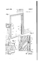
- Fig. 1. is an isometric view showing the ap- '80 plicatron of thls invention to an ornamental buck and trim utilized in a door construction and showing a method whereby the finished wall is applied in contormity with the. guide means on the buck and trim.
- Fig. 2 is a section on the line 2-2 of Fig.
- Fig. 3 is a vertical: section along the line ii-31 of a wall made up in the manner shown in Fig. 2.
- Fig. 4 is an enlarged isometrical view similar to. the portion broken away in Fig; 1 and showing the manner in which the guide feature is associated with a finished wall construction.
- Fig. 5 is a sectional view illustrating a modified form of-guidingmember.
- Fig. 6 is an isometric view showing the ap- 10B plication of a guiding member of the type shown in Figure 5 to a window frame.
- Figs. 7, 8 and 9 are views in section of constructions embodying modified methods of integrally forming the guide means with the buck.
- Figs. 10 and 11 disclose methods of application, wherein the surface finish guide made up as a separate piece by means of spot-welding or in any other manner is fixedly secured to the backhand of the buck and trim.
- Fig. 12 is a view of a further modification wherein a separate piece has been slipped over an end of the backhand and secured thereon.
- 10 indicates a door frame to which the invention has been applied, said door frame comprising a one-piece buck and trim 11, a part 12 taking the place of the ordinary buck, the ornamental work on architrave 1 1 being integral with part 12 and substituting for the trim ordinarily secured to the buck 11, and the backhand 15 formed at right angles to said ornamental work and integral therewith.
- the buck and trim 11 comprises a frame for the opening 16 in a wall construction of a finished wall and is set up in a manner hereinafter to be described.
- the door stop 18 Projecting into the opening 16 from the buck and trim 11 and integrally formed therewith'is the door stop 18 or the like. This projection is no necessary part of the construction and may, where the buck and trim 11 is used around window openings or the like, he re placed by window guides, etc. A threshold 19 may be properly positioned in opening'lfi and arranged to conform with the contour of the buck and trim 11 at this point.
- the backbands 15, as shown clearly in Fig. 2 are provided by projections 15a, 156 on the buck and trim 11 which extend toward each other and form opening 20 therebetween.
- the rough wall 21 is made up by blocks 22 or the like, positioned by the laborer to project through 'openin g 20; and then by the insertion of mortar into thespace 23 within the buck and trim 11, the relative positions of the wall 21 and buck and trim '11 are finally fixed, cut-outs 24 being provided in the backhand 15 extending into and being imbedded in this mortar, to serve as anchor members after the mortar has hardened.
- This first coat of mortar is known as the scratch coat 25.
- either plaster 26 may next be applied to finish coating the wall, or tile 27 may be positioned on coat 25 in a well-known manner.
- the bent-out portion 31 is integrally formed in the backhand 15 and forms a rib extending the buck and trim or frame or along a portion thereof, from which the mason who installs the wall construction 21 can space easily and readily the blocks 22, and which provides the bounding line for plaster or tile ositioned to form the external coat of the finished wall 17.
- a ready means for checking is thereby provided and a fixed basis set up against which the floor base or baseboard 29 may abut in fixing its relation to the buck and trim l1 and-to the finished wall 17. In the case of tiled wall constructions, a thicker coat of mortar is applied than in the case of plaster.
- a bent out portion similar to portion 31 is provided, which serves as a basis for constructions in which the wall is made of tile and the baseboard is a tile member of the type shown In Fig. 6 is disclosed an application of the invention herein described to a wall construction.
- a window frame 50 has been associated with a rough wall 51.
- a metallic locking member 52 is secured to the frame 50, said lockingmemh'er having a bent out portion 53 providing a socket 54 into which is inserted a flange 55 of a combination guide and ornamental trim 56, which flange serves to properly position the guide andtrim with respect to the frame 50.
- This guide and trim is provided on one of its surfaces with ornamental work 57, one portion of which 58 constitutes a guide with relation to which the finished wall 59 may he arranged.
- Fig. 5 is shown a portion of a buck and trim in which the backhand 15 is provided with ornamental work60 one portion of this ornamental work comprising the projection 61 which constitutes similar in nature to Fig. 6.
- Figs. 7, 8 and 9 different ways of forming the bent out portions 31, 31a are shown the surface finish guide the guide portion 58of being positioned in line with this feature of this invention re either the entire length of at 32in Fig. 3.
- bends 131, 231 and 331 are formed in the manner shown, one surface of the bend providing the fixed guiding means from which work may be carried out.
- an angle iron 33 or a bent piece of metal 34 is attached to the backband 15 in any suitable manner, as by spot welding, to present the guiding surfaces 36, 3? respectively, these corresponding to the guiding surface of bent out portions 31, 31a.
- the backhand may be either integral with or separate from the buck and ornamental trim 11 or in any other way associated therewith.
- an adjustable guide means embodying the invention is disclosed and constitutes a piece of sheet material 38 bent to provide the surface 39 as a basis for guiding work on wall 17 said piece 38 being provided with a loop 40 capable of being received on the end ll of the backband 15.
- the relative position of surface 39 may then be fixed positively as desired with respect to the edge of the bankband, as by pinching the loop 40 into contact with the backhand.
- a simple construction is provided, positively associated with the buck and trim comprising a frame about an opening in a wall construction, this construction embodying a simple means which lays down a base line from which all work on said wall is done and provides a ready check on such work either during the building operations or after they have been completed.
- a frame comprising a buck for an opening, ornamental features associated with said buck and providing a backband, said backb and including a projection, serving as a guide for finishing work on said wall,
- said first portion second portion in a direction away from said said projection being disposed inwardly of the outer portions of said back band and extending from said opening.
- a construction of the t pe described a frame comprising a buck or an opening, ornamental features associated with said buck and providing a b-ackband, said backband including a guide portion, said portion being disposed inwardly of said ornamental features and projecting away from said opening, and anchor means on said backband.
- a combination buck and trim therefor comprising a uni tary frame structure having a back band thereon, a portion of saidback band being exposed upon completion of said wall construction, and a projecting portion on said back band flush with the surface of the wall and adapted to be visible upon finishing said surface.
- a frame positioned about said opening having an exposed portion flush with said surface and a portion extending outwardly from said first portion and away from said sur extending from said opening.
Description
N. L. LIEBERMAN April 5, 1932.
WALL CONSTRUCTION Filed July 12.
1927 2 Sheets-Sheet INVENTOR NIT/MN L. L/Emm/v BY ATTORNEY April 5, 1932- N. LIEBERMAN WALL CONSTRUCTION Filed July 12. 1927 2 Sheets-Sheet Patented Apr. 5, 1932 NATHAN Ia. LIEBERMAN, OF NEW YORK, N. Y.
WALL. CONSTRUCTION Application filed' July 12,
This invention relates to an improvement in wall construction and more specifically is directed to a guide for use in finish-ingwall surfaces in the construction of new walls, or
the alterationof existingwal=ls.
The object ofthe invention is to provide, in combination with a frame, a surface finish guide associated therewith which willaiford a base line from which all wall operations may be gauged.
A further, object of the invention is to pro vide a unitary construction in which a onepiece buck and trlm or window frame is utilized and has associated therewith a means to provide a base line towhich all wall construction and finish operations might be referred, especially to indicate the proper position of finish material applied to the wall with which said buck and trimor frame is associated.
Another object of the invention is to provide a guide of the character described which shall be of simple and inexpensive construction and easily manufactured either integrally formed with a buck and trimor; frame construction or capable of simple application thereto in any other manner and which shall be practical and efficient 'n use to a high degree.
Other objects of this invention will in part be obvious and in part hereinafter pointed out.
Generally, in constructing the door and window openings for wall constructions, a framework is erected which after being properly supported serves as the base for attaching the trim or ornamental trim about the opening. Thisframework is called the buck.
In the construction illustrated on the draw- 40 ings, and described herein, the separate operations of erecting the buck and then applying the trim have been avoided by making these parts in metal or the like of one piece,
properly formed topresent the ornamental surfaces, yet of such construction that the strength of the framework greatly exceeds that of the frame used in past operations.
Generally described, the invention contemplates the construction of a buck and trim,
used in forming the frame of any opening 192?. Serial No. 205,082.
provided in wall construction, with which is to be associated a finished wall construction,
this frame carrying thereon a fixed guide which provides a basis from which'the mechanics or those in charge of the work may gauge their operations The guide may easily and quickly and check up on work done.
comprise a fixed projection on a surface of a buck or frame, orof a combination buck and trim, this pro such relation to face,
ection being provided in the deslred finished wall suras to serve as an effective guide .for
the finishing of wal'l, floor, ceiling covering, or any portlon of the buildlng construction embracing the, frame or the buck and associated parts, the buck and trim, in this instance, being anchored in any su to the structure as by means of section.
The invention accordingly consists in the itable manner an embedded features ofconstruction, combinations of elements, and arrangement of parts which will be exemplified in the construction hereinafter described, and of which the scope of application will be indicated in the following claims.
In the accompanyingdrawings, in which is shown one of the varlous possible illustrative embodiments of this invention,
Fig. 1. is an isometric view showing the ap- '80 plicatron of thls invention to an ornamental buck and trim utilized in a door construction and showing a method whereby the finished wall is applied in contormity with the. guide means on the buck and trim.
Fig. 2 is a section on the line 2-2 of Fig.
1 illustrating the application of this invention to two different types of wall finishes.
Fig. 3 is a vertical: section along the line ii-31 of a wall made up in the manner shown in Fig. 2.
Fig. 4 is an enlarged isometrical view similar to. the portion broken away in Fig; 1 and showing the manner in which the guide feature is associated with a finished wall construction.
Fig. 5is a sectional view illustrating a modified form of-guidingmember. V
Fig. 6 is an isometric view showing the ap- 10B plication of a guiding member of the type shown in Figure 5 to a window frame.
Figs. 7, 8 and 9 are views in section of constructions embodying modified methods of integrally forming the guide means with the buck.
Figs. 10 and 11 disclose methods of application, wherein the surface finish guide made up as a separate piece by means of spot-welding or in any other manner is fixedly secured to the backhand of the buck and trim.
Fig. 12 is a view of a further modification wherein a separate piece has been slipped over an end of the backhand and secured thereon.
On the drawings, 10 indicates a door frame to which the invention has been applied, said door frame comprising a one-piece buck and trim 11, a part 12 taking the place of the ordinary buck, the ornamental work on architrave 1 1 being integral with part 12 and substituting for the trim ordinarily secured to the buck 11, and the backhand 15 formed at right angles to said ornamental work and integral therewith. As shown the buck and trim 11 comprises a frame for the opening 16 in a wall construction of a finished wall and is set up in a manner hereinafter to be described.
Projecting into the opening 16 from the buck and trim 11 and integrally formed therewith'is the door stop 18 or the like. This projection is no necessary part of the construction and may, where the buck and trim 11 is used around window openings or the like, he re placed by window guides, etc. A threshold 19 may be properly positioned in opening'lfi and arranged to conform with the contour of the buck and trim 11 at this point. The backbands 15, as shown clearly in Fig. 2 are provided by projections 15a, 156 on the buck and trim 11 which extend toward each other and form opening 20 therebetween.
In setting up the wall, after the buck and trim has been properly positioned, the rough wall 21 is made up by blocks 22 or the like, positioned by the laborer to project through 'openin g 20; and then by the insertion of mortar into thespace 23 within the buck and trim 11, the relative positions of the wall 21 and buck and trim '11 are finally fixed, cut-outs 24 being provided in the backhand 15 extending into and being imbedded in this mortar, to serve as anchor members after the mortar has hardened. This first coat of mortar is known as the scratch coat 25. On top of the scratch coat, either plaster 26 may next be applied to finish coating the wall, or tile 27 may be positioned on coat 25 in a well-known manner.
It is a matter of experience that by the procedure above described the blocks 22 are not properly positioned with respect to the external edge 28 of the trim or ornamental portion 14, so that a distinct variation results in the relative exposure of backbands and the floor base or baseboard 29 when the latter is applied to the finished wall, as shown in ig. 2. In such cases, the binding edge 30 takes an irregular form, the baseboard 29 either projecting beyond the edge 28 or otherwise not edge. Furthermore, in applying the finish plaster coat 26, there is no means whereby the amount of plaster applied. can be regulated, the ocular judgment of the plasterer being entirely relied upon for the accuracy of the measurements. -Then again, no basis is given from which one in charge can check up on his employees to determine whether the finished work is according to instructions or specifications. A sides in the provision of a ready means for eliminating these objectionable features; and to thisvend the bent-out portion 31 is integrally formed in the backhand 15 and forms a rib extending the buck and trim or frame or along a portion thereof, from which the mason who installs the wall construction 21 can space easily and readily the blocks 22, and which provides the bounding line for plaster or tile ositioned to form the external coat of the finished wall 17. A ready means for checking is thereby provided and a fixed basis set up against which the floor base or baseboard 29 may abut in fixing its relation to the buck and trim l1 and-to the finished wall 17. In the case of tiled wall constructions, a thicker coat of mortar is applied than in the case of plaster. It therefore becomes necessary to provide a guide for a thicker wall portion, and as shown at 310 a bent out portion similar to portion 31 is provided, which serves as a basis for constructions in which the wall is made of tile and the baseboard is a tile member of the type shown In Fig. 6 is disclosed an application of the invention herein described to a wall construction. in which a window frame 50 has been associated with a rough wall 51. In this case, a metallic locking member 52 is secured to the frame 50, said lockingmemh'er having a bent out portion 53 providing a socket 54 into which is inserted a flange 55 of a combination guide and ornamental trim 56, which flange serves to properly position the guide andtrim with respect to the frame 50. This guide and trim is provided on one of its surfaces with ornamental work 57, one portion of which 58 constitutes a guide with relation to which the finished wall 59 may he arranged. I
In Fig. 5 is shown a portion of a buck and trim in which the backhand 15 is provided with ornamental work60 one portion of this ornamental work comprising the projection 61 which constitutes similar in nature to Fig. 6. i
In Figs. 7, 8 and 9, different ways of forming the bent out portions 31, 31a are shown the surface finish guide the guide portion 58of being positioned in line with this feature of this invention re either the entire length of at 32in Fig. 3.
wherein the bends 131, 231 and 331 are formed in the manner shown, one surface of the bend providing the fixed guiding means from which work may be carried out.
In Figs. 10 and 11, an angle iron 33 or a bent piece of metal 34 is attached to the backband 15 in any suitable manner, as by spot welding, to present the guiding surfaces 36, 3? respectively, these corresponding to the guiding surface of bent out portions 31, 31a. In these constructions, the backhand may be either integral with or separate from the buck and ornamental trim 11 or in any other way associated therewith.
In Fig. 12, an adjustable guide means embodying the invention is disclosed and constitutes a piece of sheet material 38 bent to provide the surface 39 as a basis for guiding work on wall 17 said piece 38 being provided with a loop 40 capable of being received on the end ll of the backband 15. The relative position of surface 39 may then be fixed positively as desired with respect to the edge of the bankband, as by pinching the loop 40 into contact with the backhand.
It is seen therefore that a simple construction is provided, positively associated with the buck and trim comprising a frame about an opening in a wall construction, this construction embodying a simple means which lays down a base line from which all work on said wall is done and provides a ready check on such work either during the building operations or after they have been completed.
It will thus be seen that there is provided a device in which the several objects of this invention are achieved, and which is well adapted to meet the conditions of practical use.
As various possible embodiments might be made of the above invention, and as various changes might be made in the embodiment above set forth, it is to be understood that all matter herein set forth or shown in the accompanying drawings is to be interpreted as illustrative and not in a limiting sense.
Having thus described my invention, I claim as new and desire to secure by Letters Patent 1. In combination, a rough wall having an opening therein, a frame positioned about said opening, and means on said frame to provide a guide for finish work on said wall, said means comprising an angle shaped portion having a wall extending away from said opening and a wall flush with said finished work and adapted to be visible upon completion of said finished work.
2. In wall construction of the type described, a frame comprising a buck for an opening, ornamental features associated with said buck and providing a backband, said backb and including a projection, serving as a guide for finishing work on said wall,
' face, said first portion second portion in a direction away from said said projection being disposed inwardly of the outer portions of said back band and extending from said opening.
3. A construction of the t pe described, a frame comprising a buck or an opening, ornamental features associated with said buck and providing a b-ackband, said backband including a guide portion, said portion being disposed inwardly of said ornamental features and projecting away from said opening, and anchor means on said backband.
4:. In wall construction having an opening therein, a frame positioned about said opening and means on said frame inward of the external edge of said frame for guiding work done on said wall, said means comprising a member adapted to be visible after finishing said wall construction.
5. In wall construction, a combination buck and trim therefor comprising a uni tary frame structure having a back band thereon, a portion of saidback band being exposed upon completion of said wall construction, and a projecting portion on said back band flush with the surface of the wall and adapted to be visible upon finishing said surface.
6. In combination with a building wall having an opening and a finished surface on one side thereof surrounding said opening, a frame positioned about said opening having an exposed portion flush with said surface and a portion extending outwardly from said first portion and away from said sur extending from said opening.
In testimony whereof I aflix my signature.
NATHAN L. LIEBERMAN.
Priority Applications (1)
| Application Number | Priority Date | Filing Date | Title |
|---|---|---|---|
| US205082A US1852017A (en) | 1927-07-12 | 1927-07-12 | Wall construction |
Applications Claiming Priority (1)
| Application Number | Priority Date | Filing Date | Title |
|---|---|---|---|
| US205082A US1852017A (en) | 1927-07-12 | 1927-07-12 | Wall construction |
Publications (1)
| Publication Number | Publication Date |
|---|---|
| US1852017A true US1852017A (en) | 1932-04-05 |
Family
ID=22760722
Family Applications (1)
| Application Number | Title | Priority Date | Filing Date |
|---|---|---|---|
| US205082A Expired - Lifetime US1852017A (en) | 1927-07-12 | 1927-07-12 | Wall construction |
Country Status (1)
| Country | Link |
|---|---|
| US (1) | US1852017A (en) |
-
1927
- 1927-07-12 US US205082A patent/US1852017A/en not_active Expired - Lifetime
Similar Documents
| Publication | Publication Date | Title |
|---|---|---|
| US2245785A (en) | Wall tile | |
| US20190169918A1 (en) | Window reveal systems and methods | |
| US3391509A (en) | Drywall edge construction and finishing channel | |
| US2854843A (en) | Plaster ground | |
| US2598139A (en) | Metallic door frame securing clip | |
| US2796641A (en) | Wallboard trim | |
| US2234043A (en) | Wall opening construction | |
| US1852017A (en) | Wall construction | |
| US3213577A (en) | Screed base and tool for wall structures | |
| US1838129A (en) | Metal buck and trim | |
| US1798280A (en) | Wall construction | |
| US3683573A (en) | Process for covering buildings, particularly dwellings, and the dwellings obtained by application of this or a similar process | |
| US1335378A (en) | Molding for plastered walls | |
| US1520782A (en) | Wall construction | |
| US1737403A (en) | Door framing | |
| US6860072B2 (en) | Retrofit casing head apparatus and method | |
| US1765712A (en) | Door casing | |
| KR20100002876U (en) | Tile finishing frame | |
| US1738256A (en) | Bathtub and similar structure | |
| KR102064633B1 (en) | Finishing material for remodeling window | |
| US1524145A (en) | Adjustable frame for ventilators and the like | |
| US1924971A (en) | Plaster terminal | |
| USRE17164E (en) | Wall louver ventilator | |
| US1691371A (en) | Frame construction | |
| US2041942A (en) | Building unit |