US1852007A - Shackle line swing - Google Patents
Shackle line swing Download PDFInfo
- Publication number
- US1852007A US1852007A US297194A US29719428A US1852007A US 1852007 A US1852007 A US 1852007A US 297194 A US297194 A US 297194A US 29719428 A US29719428 A US 29719428A US 1852007 A US1852007 A US 1852007A
- Authority
- US
- United States
- Prior art keywords
- swing
- arms
- bearing
- arm
- shackle
- Prior art date
- Legal status (The legal status is an assumption and is not a legal conclusion. Google has not performed a legal analysis and makes no representation as to the accuracy of the status listed.)
- Expired - Lifetime
Links
- 230000000694 effects Effects 0.000 description 4
- 238000009877 rendering Methods 0.000 description 4
- 238000005452 bending Methods 0.000 description 3
- 238000010276 construction Methods 0.000 description 3
- 230000004048 modification Effects 0.000 description 3
- 238000012986 modification Methods 0.000 description 3
- 238000005266 casting Methods 0.000 description 2
- 230000007423 decrease Effects 0.000 description 2
- 230000003247 decreasing effect Effects 0.000 description 2
- 238000007689 inspection Methods 0.000 description 2
- 238000005461 lubrication Methods 0.000 description 2
- 238000010008 shearing Methods 0.000 description 2
- 125000006850 spacer group Chemical group 0.000 description 2
- 241000022563 Rema Species 0.000 description 1
- 241000364021 Tulsa Species 0.000 description 1
- 239000011358 absorbing material Substances 0.000 description 1
- 238000009825 accumulation Methods 0.000 description 1
- 238000006243 chemical reaction Methods 0.000 description 1
- 238000004140 cleaning Methods 0.000 description 1
- 230000007547 defect Effects 0.000 description 1
- 230000003292 diminished effect Effects 0.000 description 1
- 230000003467 diminishing effect Effects 0.000 description 1
- 230000008030 elimination Effects 0.000 description 1
- 238000003379 elimination reaction Methods 0.000 description 1
- 238000011010 flushing procedure Methods 0.000 description 1
- 230000005484 gravity Effects 0.000 description 1
- 238000009434 installation Methods 0.000 description 1
- 230000001788 irregular Effects 0.000 description 1
- 238000004519 manufacturing process Methods 0.000 description 1
- 239000000463 material Substances 0.000 description 1
- 238000000926 separation method Methods 0.000 description 1
- 239000007787 solid Substances 0.000 description 1
- 239000002699 waste material Substances 0.000 description 1
- XLYOFNOQVPJJNP-UHFFFAOYSA-N water Substances O XLYOFNOQVPJJNP-UHFFFAOYSA-N 0.000 description 1
Images
Classifications
-
- F—MECHANICAL ENGINEERING; LIGHTING; HEATING; WEAPONS; BLASTING
- F04—POSITIVE - DISPLACEMENT MACHINES FOR LIQUIDS; PUMPS FOR LIQUIDS OR ELASTIC FLUIDS
- F04B—POSITIVE-DISPLACEMENT MACHINES FOR LIQUIDS; PUMPS
- F04B47/00—Pumps or pumping installations specially adapted for raising fluids from great depths, e.g. well pumps
- F04B47/02—Pumps or pumping installations specially adapted for raising fluids from great depths, e.g. well pumps the driving mechanisms being situated at ground level
- F04B47/026—Pull rods, full rod component parts
-
- Y—GENERAL TAGGING OF NEW TECHNOLOGICAL DEVELOPMENTS; GENERAL TAGGING OF CROSS-SECTIONAL TECHNOLOGIES SPANNING OVER SEVERAL SECTIONS OF THE IPC; TECHNICAL SUBJECTS COVERED BY FORMER USPC CROSS-REFERENCE ART COLLECTIONS [XRACs] AND DIGESTS
- Y10—TECHNICAL SUBJECTS COVERED BY FORMER USPC
- Y10T—TECHNICAL SUBJECTS COVERED BY FORMER US CLASSIFICATION
- Y10T403/00—Joints and connections
- Y10T403/32—Articulated members
- Y10T403/32254—Lockable at fixed position
- Y10T403/32262—At selected angle
- Y10T403/32319—At selected angle including pivot stud
- Y10T403/32327—At selected angle including pivot stud including radially spaced detent or latch component
- Y10T403/32336—Engaging notch or recess in outer periphery of component
-
- Y—GENERAL TAGGING OF NEW TECHNOLOGICAL DEVELOPMENTS; GENERAL TAGGING OF CROSS-SECTIONAL TECHNOLOGIES SPANNING OVER SEVERAL SECTIONS OF THE IPC; TECHNICAL SUBJECTS COVERED BY FORMER USPC CROSS-REFERENCE ART COLLECTIONS [XRACs] AND DIGESTS
- Y10—TECHNICAL SUBJECTS COVERED BY FORMER USPC
- Y10T—TECHNICAL SUBJECTS COVERED BY FORMER US CLASSIFICATION
- Y10T74/00—Machine element or mechanism
- Y10T74/20—Control lever and linkage systems
- Y10T74/20576—Elements
- Y10T74/20582—Levers
- Y10T74/20606—Swing posts
Definitions
- My invention relates to improvements in a shackle line swing in which the direction of motion of the rods may be changed through an angle from nothing to 90. Furthermore,
- my construction is such that the length of the output stroke may be decreased or increased over the input stroke thus rendering separate equipment to obtain that result unnecessary and resulting in one of those economies so necessary and desired in the modern field of invention.
- Still another important feature of my swing is its ready adjustment from about a right angle down to nothing. This adjustment permits the ingoing and outgoing shackle rods or lines to be set attheir most eflicient angle with the consequent saving of ower. 1
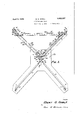
- Fig. 1 is a plan view of the entire swing.
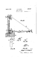
- Fig. 2 is a vertical section taken along line 22, Fig. 1, the channel barswhich connect the two arms being broken away for the sake of clearness.
- Fig. 3 is a horizontal section taken along either line 33, Fig. 2, one arm being entirely omitted and the other shown in its inner posi tion.
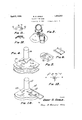
- Fig. 4 is an isometric view of the quadrant shaped main supporting plate.
- Fig. 5 is an isometric of one of the four shoes which are pivotally secured to the plate.
- Fig. 6 is a View showing the arrangement of holes in the inner ends of theseveral channel bars which form the two arms.
- Fig. 7 is an isometric view of the curved face locking washer which fits inside of the main post or support.
- Fig. 8 is a perspective View of the tie rod journal.
- Fig. 9 shows the spherical washer used at several points in the assembly.
- Fig. 10 is a perspective view of the block seat for the washer.
- Fig. 11 shows a plan view of the clip which connects either'of the braces to the main post.
- Fig. 12 is a section on line 1212 of Fig. 11.
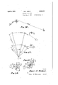
- Fig. 13 is a diagrammatic sketch showing the point of maximum pressure between the lower ourn al and its bearings.
- Fig. 14 is an enlarged view showing the double fastening device used between the arms and the cross brace.
- Fig. 15 is also a view of this connection between the brace and an arm but the brace is in an inclined position due to the fact that the swing is being used as a multiplier. i. e. the input arm length is less than the output arm length.
- Fig. 16 is a plan view of a typical arrangement wherein the incoming shackle line is of a much different length than the outgoing thus giving rise to variations in the arc traveled by the swing.
- Fig. 17 is a diagrammatic sketch showing how the doubling or increasing the length of the arms of the swing produces a much better pulling system.
- Fig. 18 discloses a modification of the quad rant shaped oscillating plate.
- numeral 10 indicates a base in which the upright pipe or post 11 is rigidly embedded. It'is made more solid by partly filling it with concrete as shown in Fig. 2.
- Angle braces 12 and 13 are adj ustably secured at 14 and 15 respectively, the usual bolts being passed through the chosen one of the several holes 16 and 17
- the upper ends of these braces are threaded and pass through holes in clips 18.
- these clips have a hole 19, the ends of said hole being enlarged and spherical in shape.
- A. spherical washer, 33 as shown in fits in each semi-spherical socket or hole and are locked in place by the usualnut-s on eachside thereof.
- the smaller end of the clip is curved to fit'theoutside of the pipe and is bolted thereon.
- the innernut of the lower clip bolt is provided with a locking washer 20 as shown in Fig. 7.
- This washer has a curved surface 21 to conform with the inner surface of the upright post or pipe and a recess 22 wherein the head of the bolt seats and thus is prevented from turning as the nut is tightened.
- a quadrant shaped plate member 23 Pivotally mounted near the bottom of this pipeis a quadrant shaped plate member 23, preferably a casting, and arms 24 and 24' are pivotally mounted on this plate member. These arms are adjustably connected near their outer ends by a cross member 26. Thus these arms may be extended to their maximum position of about a right angle or else pulled adjacent each other thereby forming in effect a single arm.
- Arm 24 is composed of a lower member 28 and an upper member 27, preferably channel bars, and these members are fastened together by spacers 29 and 92 as well as the bearing 30.
- This bearing is adjustable lengthwise along the arm through the medium of the several holes 31.
- a clip 32 is fastened by the usual bolt or rivet means.
- a tie-rod 34 extends through this clip and is passed through anelongated slot 35 in the wing 36 of the winged supporting journal 37 A spherical washer33, as.
- Fig. 2 is inserted between the upper nut and the wing 36 thus forming a bearing whereby the tie rod may be swungthrough its arc in the slot thus remaining in the vertical projection of a true radius about the central rotating axis and thus relieving the several parts from anyuncalled for strain.
- This combination of arcuate slot and its seat together with the semi-spherical washer is an important feature of my invention as it permits the several adjustments of the arms to be made with ease.
- a similar washer 33 is likewise inserted between clip 32 and the lower end of the tie rod.
- Arm 24 is similar to arm 24 being formed of upper member 27 and lower member 28 spaced by the spacers 29 and 92 and the pull bearing 30, said pull bearing being mounted in any of the desired holes 31'.
- a clip 32 is fastened to the upper channel member 27 by means of the usual nut and bolt connection.
- a tie-rod 34 supports the arm and its appurtenances. This tie-rod is also rotatably slidably mounted in a spherical bearing which relieves the parts of any strain during movement of the rod in slot 35 in the wing 36 of the support 37.1
- The'winged supporting journal 37 is rotatably mounted in cup bearing 38 which is rigidly fastened'to pipe 11 by the usual bolts fitted with lock washers 20, see Fig. 7.
- a hole or duct 41 connects the bottom of the cup to the outside periphery of the cup bearing and is normally closed by means of the plug 42.
- the duct 41 is enlarged to form a dirt reservoir 43 as clearly'shown in Fig. 2.
- plug 42 is removed and the bearing cleaned by pouring flushing oil around the upper edge and allowing it to run through thereby removing all foreign material from the cup.
- an open bearing 50 is rigidly secured by means of the U-bolt clamp 51.
- the inner periphery of this bearing is chamfered as shown at 52 and oil absorbing material 53 is provided if desired.
- a closed or cup bearing 54 which is also rigidly secured to the central post by means of a U-bolt clam 55.
- This cup caring 54 is somewhat similar to the upper cup bearing having a duct 93, a reservoir 94 and a closing plug 95, functioning in the same man ner with respect to cleaning as well as running in a bath of oil.
- a duct 93 a duct 93
- a reservoir 94 a reservoir 94
- a closing plug 95 functioning in the same man ner with respect to cleaning as well as running in a bath of oil.
- Slots 64 are circumferentially formed about a circle having its center at the points or holes 58 and 59. These slots cooperate with bolts 67, 68, 69 and 70 to fasten the arms in their proper position.
- a cross web 65 between the slots serves to strengthen the plate and the two holes, 71 and 72, see 5, are spaced a slight distance apart circumferentially whereby the arms 24 and 24 may be fastened by one bolt at least in any position within the designed maximum limit.
- the cross brace 26 attention is called tothe severe tension which it must transmit. It is formed of two members, the top one being fastened at one end to the top member of the arm member 24 and at the other end to the top member of the arm 24'. As shown in Fig.
- a further provision against separation of these arms is provided by bolt 80, the head of which is fastened the desired one of the series of holes 87. See Figs. 14 and 15.
- An element 81 is fastened by bolt 86 in the desired hole of the series of holes 31, these holes also being used to fasten the shackle rod bearings 30 and 30 to the arms 24 and 24.
- the bolt 80 is passed through a slot 82 in element 81.
- the large end of the slot terminates adjacent a vertical cylindrical surface 88 and a washer 84, curved in a similar plane, passes over the bolt and is held adjacent surface 88 by means of the usual nut 85.
- Fig. 16 E represents the power producer or prime mover and P indicates the pump. Intermediate these two the swing, S, is shown, 10 indicating the base thereof and 11 the main upright or post.
- S the swing
- 10 indicating the base thereof
- 11 the main upright or post.
- Iobtain Y 50 0.000006 2200 0.66 01- foot.
- A. small radius swing and my swing are diagrammatically compared in Fig. 17.
- the arm or radius of the small or present day swing is made one unit in length whereas in my new and improved swing the radius is two units in length. This is approximately the situation.
- AB is the length of stroke desired and in the sketch AB is equal to AB by construction. But, due to the differences in to a clip 79 mounted in their radii, the present day 1 swing must swing through Whereas my swing travels through only 30.
- Fig. 16 also shows how the longer armed swing eliminates the point past which it is practically impossible to operate the swing.
- This point is known in the oil mans vernacular as the fouling point and it is designated by D in Fig. 17 in the shorter swing and D in the longer swing.
- Inspection of Fig. 17 shows that the angles between the direction of pull of the shackle rods, as indicated by the several arrows, and the radii coincident with DD are the samebut it is also obvious that the fouling point D will never be reached in actual practice whereas D may often be passed or exceeded thus fouling or breaking the line with its consequent expense.
- the position of the pivot points D and D are as important as the leverage arms since when these points approach the ends of the stroke the more indirect the pull becomes and the nated by 56 nearer the fouling point is approached.
- Fig. 18 shows a modification of the quadrant shaped plate and its connection to the arms.
- the arms are directly pivoted to the integral plate and the use of the shoes are eliminated.
- This plate, designated 23 is symmetrical about its central horizontal axis thereby rendering it economical to manufacture. Its upper stem is desig-
- the pivot holes for the arms, only arm 24 being shown, are designated 58 and 59 Slots 64: are provided about the pivotal centers for a single fastening bolt in each arm.
- the arms are separated to their full extent but by removing bolts 67-70, and the connectors between the cross arm 26 and the arms 24 and 24 the angle between the arms may be decreased to the proper efiicient angle. only one of the arms may be adjusted.
- a swing consisting of a post, a plate member pivotally mounted thereon, arms having one end pivotally mounted on said plate member, an upper member pivotally mounted on said post, said upper member having slots therethrough, the upper ends of the slots being enlarged to form semi-spherical seats, and rods fastened to the outer ends of the arms and passing through the slots in the upper member, semi-spherical washers slipped over the rods into the said seats and means for retaining said washers in position whereby the arms may swing easily about the central pivot.
- aligned holes means for connecting the same consisting of; flat washer blocks each having a semi-spherical recess adjacent opposite sides of the bar and arms, semi-spherical washers in said recesses and means extending through said washers, blocks, and the aligned holes in the bar and arm to hold the same together.
- a swing consisting of a post, a plate pivoted thereon, an arm, a shoe having a recess therein adapted to receive the end of the arm, said shoe having its end curved, means for pivotally mounting said shoe on the plate at a center from which at least part of said curve is struck and means on the plate abutting the curved end of the shoe.
- a swing consisting of a post, a plate member pivotally mounted thereon, arms having semi-circular ends pivotally mounted onto said plate member, means on the plate member abutting the ends of said arms, said abutting means extending on either side of the longitudinal axes of the arms regardless of their positions, and all adjustable cross member connecting the arms whereby the distance between them may be varied.
- a swing for shackle rod lines comprising a vertical support, an upper bearing thereon, a revoluble element therein, a lower bearing on the support, a horizontal arm revoluble in said lower bearing independently of the movement of the said revoluble element and brace means between said revoluble element and said horizontal arm, said brace means including self aligning connections at either end thereof whereby it mayalign itself between the revoluble element and the revoluble arm.
Landscapes
- Engineering & Computer Science (AREA)
- Mechanical Engineering (AREA)
- General Engineering & Computer Science (AREA)
- Pivots And Pivotal Connections (AREA)
Description
April 5, 1932. B. G. GOBLE SHACKLE LINE swme Filed Aug. 5, 1928 4 Sheets-Sheet Inventor BERT 6. 60545.
67% X7 @awm/ru Attorney A ril 5, 1932. B BLE I 1,852,007'
SHACKLE LINE SWING Filed Aug. 5, 1928 4 Sheets-Sheet 2 Invgntor 5527' 6. GoaLE.
(707911 Allorney April 5, 1932. B. e. GOBLE SHACKLE LINE SWING Filed Aug. 5, 1928 4 Sheets-Sheet 3 BERT 6. 6051.5.
(7m 17. Attbrney April 5, 1932. a GQBLE 1,852,007
SHACKLE LINE SWING Filed Aug. 3, 1928 4 Sheets-Sheet 4 lnventor BERT G. GOBLE.
(7m @avna/rv. Attorney Patented Apr. 5, 1932 UNITE STATES PATENT GFFHJE BERT G. G OBLE, OF TULSA, OKLAHOMA, .AS SIGNOR TO W. A. QUIGLEY:
SHACKLE LINE SWING Application filed. August 3, 1928. Serial No. 297,194.
My invention relates to improvements in a shackle line swing in which the direction of motion of the rods may be changed through an angle from nothing to 90. Furthermore,
my construction is such that the length of the output stroke may be decreased or increased over the input stroke thus rendering separate equipment to obtain that result unnecessary and resulting in one of those economies so necessary and desired in the modern field of invention.
One of-the defects of all the existing types of swings lies in the fact that a single lower bearing and its journal must receive both the thrust due to the pull on the two shackle lines, and the downward twist, due to gravitys effect upon the several oscillating parts which are suspended in cantilever fashion from a central support. As this strain on the single bearing is very great it is impossible to fasten the shackle lines more than a few feet from the central support and still obtain a practical working device. The present day practice is to use a swing having a maximum radius of four feet.
This practice obtains although practical men realize that an easier pull would be obtained if the lines were attached farther away from the center due to fact that it is necessary to keep the leverage points in a correct position relative to the fulcrum. In other words the less arc traveled through by the arms the less variation or rather diminishing of the effective lever arm will occur.
Furthermore a variation from the proper setting of the swing may be caused by improper installation, or even temperature changes, and such variations shift the arc in which the swing should normally operate thus resulting in an increase of power necessary to operate the well and in some cases resulting in a broken line or swing due to such excessive overload. Such a break may occur at night with its consequent loss of oil and perhaps several days loss of oil due to the accumulation of water in the well.
One of my problems was the elimination of the binding of the single bearing and I solved this by adding another bearing and connecting the oscillating arms thereto by the use of tension members. These members are shown in the form of tie-rods and radiate downwardly from the upper additional bearing in a sort of merry-go-round fashion.
By the use of the supporting means (16- scribed above I am able to make apractical swing which holds the shackle lines a farther distance from the central bearing and thus cuts down the variation ofthe effective lever arm during the stroke of the swing and also prevents considerable bending of the shackle lines at their pointsof connections with the swing. This bending also occasionsloss of power.
Another important feature of my swing is its lubrication. system. Certain of the bearings are cupped and consequently the journals may run in a continuous bath of oil with correspondingly high efficiency while in the rema ningjournal boxes I provide a groove or hole on that side of the bearing at which the maximum pressure occurs and thus I prevent the leakage and waste of oil but nevertheless furnish the requisite amount of oil at'the" point where it is most needed. H
Still another important feature of my swing is its ready adjustment from about a right angle down to nothing. This adjustment permits the ingoing and outgoing shackle rods or lines to be set attheir most eflicient angle with the consequent saving of ower. 1
Other objects will appear, or become 0b vious, or will suggest themselves during the description of my swing shown in the accompanying drawings, in which;
Fig. 1 is a plan view of the entire swing.
Fig. 2 is a vertical section taken along line 22, Fig. 1, the channel barswhich connect the two arms being broken away for the sake of clearness. p y
Fig. 3 is a horizontal section taken along either line 33, Fig. 2, one arm being entirely omitted and the other shown in its inner posi tion.
Fig. 4 is an isometric view of the quadrant shaped main supporting plate.
Fig; 5 is an isometric of one of the four shoes which are pivotally secured to the plate.
Fig. 6 is a View showing the arrangement of holes in the inner ends of theseveral channel bars which form the two arms.
Fig. 7 is an isometric view of the curved face locking washer which fits inside of the main post or support.
Fig. 8 is a perspective View of the tie rod journal.
Fig. 9 shows the spherical washer used at several points in the assembly.
Fig. 10 is a perspective view of the block seat for the washer.
Fig. 11 shows a plan view of the clip which connects either'of the braces to the main post.
Fig. 12 is a section on line 1212 of Fig. 11.
Fig. 13 is a diagrammatic sketch showing the point of maximum pressure between the lower ourn al and its bearings.
Fig. 14 is an enlarged view showing the double fastening device used between the arms and the cross brace.
Fig. 15 is also a view of this connection between the brace and an arm but the brace is in an inclined position due to the fact that the swing is being used as a multiplier. i. e. the input arm length is less than the output arm length.
Fig. 16 is a plan view of a typical arrangement wherein the incoming shackle line is of a much different length than the outgoing thus giving rise to variations in the arc traveled by the swing.
Fig. 17 is a diagrammatic sketch showing how the doubling or increasing the length of the arms of the swing produces a much better pulling system.
Fig. 18 discloses a modification of the quad rant shaped oscillating plate.
Referring now more particularly to the drawings, numeral 10 indicates a base in which the upright pipe or post 11 is rigidly embedded. It'is made more solid by partly filling it with concrete as shown in Fig. 2. Angle braces 12 and 13 are adj ustably secured at 14 and 15 respectively, the usual bolts being passed through the chosen one of the several holes 16 and 17 The upper ends of these braces are threaded and pass through holes in clips 18. As shown in Figs. 11 and 12. these clips have a hole 19, the ends of said hole being enlarged and spherical in shape. A. spherical washer, 33, as shown in fits in each semi-spherical socket or hole and are locked in place by the usualnut-s on eachside thereof. The smaller end of the clip is curved to fit'theoutside of the pipe and is bolted thereon. By this construction I obtain real.- ly rigid brace which precludes loosening by its original super-tight condition. Y
j The innernut of the lower clip bolt is provided with a locking washer 20 as shown in Fig. 7. This washer has a curved surface 21 to conform with the inner surface of the upright post or pipe and a recess 22 wherein the head of the bolt seats and thus is prevented from turning as the nut is tightened.
Thus, by the above adjustable braces the pipe is held in or moved to an exact vertical position.
Pivotally mounted near the bottom of this pipeis a quadrant shaped plate member 23, preferably a casting, and arms 24 and 24' are pivotally mounted on this plate member. These arms are adjustably connected near their outer ends by a cross member 26. Thus these arms may be extended to their maximum position of about a right angle or else pulled adjacent each other thereby forming in effect a single arm.
shown by Fig. 2, is inserted between the upper nut and the wing 36 thus forming a bearing whereby the tie rod may be swungthrough its arc in the slot thus remaining in the vertical projection of a true radius about the central rotating axis and thus relieving the several parts from anyuncalled for strain. This combination of arcuate slot and its seat together with the semi-spherical washer is an important feature of my invention as it permits the several adjustments of the arms to be made with ease. A similar washer 33 is likewise inserted between clip 32 and the lower end of the tie rod.
Near the bottom of the pipe post an open bearing 50 is rigidly secured by means of the U-bolt clamp 51. The inner periphery of this bearing is chamfered as shown at 52 and oil absorbing material 53 is provided if desired.
Juxtaposed below this open bearing is a closed or cup bearing 54 which is also rigidly secured to the central post by means of a U-bolt clam 55.
This cup caring 54, as shown in Fig. 2, is somewhat similar to the upper cup bearing having a duct 93, a reservoir 94 and a closing plug 95, functioning in the same man ner with respect to cleaning as well as running in a bath of oil. With respect to the novel lubrication feature attention is directed to Fig. 13. 1
In Fig. 13 the arms 24 and 24 are indicated diagrammatically and F and F represent the forces acting along the two shackle lines. In order that the system may remain in equilibrium the vector sum of these. two forces must be'exactly opposed and obviously this reaction F, is furnished by the pipe 11 with its supporting braces. Furthermore, it is apparent from an inspection of Fig. 13 that since arms 24 and 24 swing only 90 maximum, never below the dotted line, H-H, Fig. 13, their resultant likewise oscillates only through a right angle and this point, called the point of maximum pressure is designated by character P. This point P as shown on Fig. 13 lies directly on a line bisecting the are through which the swing operates and consequently it is at this point that a tight fit between the bearing and its journal would prevail during the working stroke of the swing. 'Hence at a corresponding point 96, Fig. 2, I provide a thin vertical groove which is supp-lied with oil in any desired manner. Likewise, grooves 97 and 97 are provided in bearings 30 and 30 respectively, as shown in Fig. 1.
Revolubly mounted in these aligned bearings are the stems 56 and 57 of the quadrant shaped plate or member, this member being symmetrical about a central horizontal axis as shown in Fig. 2. As shown clearly in Fig. 4 this casting has holes 58 and 59 extending therethrough, these holes containing bolts 60 and 61 which serve as pivot points for'the swinging of the two arms 24 and 24 apart or together as the case may be. Arc shaped surfaces 62 and 63- are provided against which the curved ends of shoes 66 reside or push and thus relieve the bolts 60 and 61 of shearing stress.
Slots 64 are circumferentially formed about a circle having its center at the points or holes 58 and 59. These slots cooperate with bolts 67, 68, 69 and 70 to fasten the arms in their proper position. A cross web 65 between the slots serves to strengthen the plate and the two holes, 71 and 72, see 5, are spaced a slight distance apart circumferentially whereby the arms 24 and 24 may be fastened by one bolt at least in any position within the designed maximum limit. Referring now to the cross brace 26, attention is called tothe severe tension which it must transmit. It is formed of two members, the top one being fastened at one end to the top member of the arm member 24 and at the other end to the top member of the arm 24'. As shown in Fig. 2 these members are adjacent each other and a bolt extends through a. hole in each. On each end of the bolt a bearing block 75, together with its spherical bearing washer 33, is placed and the fiat members are thus drawn tightly together over their entire surfaces thus rendering them susceptible to shear over their more or less irregular surfaces and thus providing a connection whose strength far exceedsthe mere shearing strength of the bolt. I
A further provision against separation of these arms is provided by bolt 80, the head of which is fastened the desired one of the series of holes 87. See Figs. 14 and 15. An element 81 is fastened by bolt 86 in the desired hole of the series of holes 31, these holes also being used to fasten the shackle rod bearings 30 and 30 to the arms 24 and 24. Now the bolt 80 is passed through a slot 82 in element 81. As shown in enlarged Figs. 14 and 15, the large end of the slot terminates adjacent a vertical cylindrical surface 88 and a washer 84, curved in a similar plane, passes over the bolt and is held adjacent surface 88 by means of the usual nut 85.
l/Vith reference to Fig. 16 E represents the power producer or prime mover and P indicates the pump. Intermediate these two the swing, S, is shown, 10 indicating the base thereof and 11 the main upright or post. In order to show the effect of a temperature change on the length of a string of shackle line rods I will assume a temperature change of 50. The coeflicient of expansion is roughly 0.000006. Thus Iobtain Y 50 0.000006 2200=0.66 01- foot.
As the usual temperature range during the year is about twice that above considered, or 100, is is seen that this factor is not negligible especially in the present day short armed swings.
A. small radius swing and my swing are diagrammatically compared in Fig. 17. For convenience the arm or radius of the small or present day swing is made one unit in length whereas in my new and improved swing the radius is two units in length. This is approximately the situation. AB is the length of stroke desired and in the sketch AB is equal to AB by construction. But, due to the differences in to a clip 79 mounted in their radii, the present day 1 swing must swing through Whereas my swing travels through only 30. By computation, which it is not deemed necessary to set forth as the drawings are to scale, it is found that the leverage or effective radius in the smaller swing decreases from one unit to one unitless 0.268 or 73.2% whereas the larger improved swing decreases from 2 units to 2 units less 0.068 or about 96%. The above forcibly brings out the saving effect by maintaining a constant length leverage or thereabouts.
Fig. 16 also shows how the longer armed swing eliminates the point past which it is practically impossible to operate the swing. This point is known in the oil mans vernacular as the fouling point and it is designated by D in Fig. 17 in the shorter swing and D in the longer swing. Inspection of Fig. 17 shows that the angles between the direction of pull of the shackle rods, as indicated by the several arrows, and the radii coincident with DD are the samebut it is also obvious that the fouling point D will never be reached in actual practice whereas D may often be passed or exceeded thus fouling or breaking the line with its consequent expense. Also, from this Fig. 17 it can be realized that the position of the pivot points D and D are as important as the leverage arms since when these points approach the ends of the stroke the more indirect the pull becomes and the nated by 56 nearer the fouling point is approached.
Furthermore, not only is the effective pulling or lever arm greatly diminished in the smaller swing but much energy is consumed in the bending of the shackle line as the swing connection thereto travels along the radius of the arc. Another disadvantage of the smaller swing is seen by assuming that the shackle line which is fastened thereto is slightly short. Thus, the point of connection of the small swing, designated C, would have to travel a distance of M, which is about twice as great as the corresponding distance L in the larger swing.
Fig. 18 shows a modification of the quadrant shaped plate and its connection to the arms. In this modification the arms are directly pivoted to the integral plate and the use of the shoes are eliminated. This plate, designated 23 is symmetrical about its central horizontal axis thereby rendering it economical to manufacture. Its upper stem is desig- The pivot holes for the arms, only arm 24 being shown, are designated 58 and 59 Slots 64: are provided about the pivotal centers for a single fastening bolt in each arm.
As shown in Fig. 1 the arms are separated to their full extent but by removing bolts 67-70, and the connectors between the cross arm 26 and the arms 24 and 24 the angle between the arms may be decreased to the proper efiicient angle. only one of the arms may be adjusted.
Having thus described my invention I desire it to be understood that the inventionis in no wise limited to the particular illustrative embodiment disclosed, the scope thereof being set forth in the following claims. I claim: r 1. In combination; a post; a plate member pivoted thereon; arms pivoted on said plate member; said plate member having slots circumscribed about each arm pivot point and sdaid arms having spaced holes on the same rams, the slots and holes whereby the arms may be adjusted and clamped at any position desired within their maximum limit. 2. A swing consisting of a post, a plate member pivotally mounted thereon, arms having one end pivotally mounted on said plate member, an upper member pivotally mounted on said post, said upper member having slots therethrough, the upper ends of the slots being enlarged to form semi-spherical seats, and rods fastened to the outer ends of the arms and passing through the slots in the upper member, semi-spherical washers slipped over the rods into the said seats and means for retaining said washers in position whereby the arms may swing easily about the central pivot.
3. In a swing having a rigid vertical pipe and a brace therefor the combination of; a
clip having two legs, one leg being fastened to the pipe and the other leg having a hole through which the brace extends, spherical recesses at each end of said hole and spherical Obviously, if desired,
washers on said brace fitting said recesses and means for forcing the washers along the brace into contact with said leg.
4. In a swing the combination of two members pivoted together, abolt fastened to one of these members, a hole in the other member an element rigidly connected with said last named member, said element having a slot and a circular seat, said seat being cylindrical in shape and parallel to the pivot of the two members and said slot being in alignment with the hole, and said bolt passing through the hole and slot, and fastening means on said bolt contacting with the circular seat.
5. In a swing having an upright pipe with arms independently pivoted thereto and a cross bar connecting the arms, aligned holes means for connecting the same consisting of; flat washer blocks each having a semi-spherical recess adjacent opposite sides of the bar and arms, semi-spherical washers in said recesses and means extending through said washers, blocks, and the aligned holes in the bar and arm to hold the same together.
6. A swing consisting of a post, a plate pivoted thereon, an arm, a shoe having a recess therein adapted to receive the end of the arm, said shoe having its end curved, means for pivotally mounting said shoe on the plate at a center from which at least part of said curve is struck and means on the plate abutting the curved end of the shoe.
7. A swing consisting of a post, a plate member pivotally mounted thereon, arms having semi-circular ends pivotally mounted onto said plate member, means on the plate member abutting the ends of said arms, said abutting means extending on either side of the longitudinal axes of the arms regardless of their positions, and all adjustable cross member connecting the arms whereby the distance between them may be varied.
8. A swing for shackle rod lines comprising a vertical support, an upper bearing thereon, a revoluble element therein, a lower bearing on the support, a horizontal arm revoluble in said lower bearing independently of the movement of the said revoluble element and brace means between said revoluble element and said horizontal arm, said brace means including self aligning connections at either end thereof whereby it mayalign itself between the revoluble element and the revoluble arm.
In testimony whereof I afiix my signature.
BERT G. GOBLE.
Priority Applications (1)
| Application Number | Priority Date | Filing Date | Title |
|---|---|---|---|
| US297194A US1852007A (en) | 1928-08-03 | 1928-08-03 | Shackle line swing |
Applications Claiming Priority (1)
| Application Number | Priority Date | Filing Date | Title |
|---|---|---|---|
| US297194A US1852007A (en) | 1928-08-03 | 1928-08-03 | Shackle line swing |
Publications (1)
| Publication Number | Publication Date |
|---|---|
| US1852007A true US1852007A (en) | 1932-04-05 |
Family
ID=23145249
Family Applications (1)
| Application Number | Title | Priority Date | Filing Date |
|---|---|---|---|
| US297194A Expired - Lifetime US1852007A (en) | 1928-08-03 | 1928-08-03 | Shackle line swing |
Country Status (1)
| Country | Link |
|---|---|
| US (1) | US1852007A (en) |
-
1928
- 1928-08-03 US US297194A patent/US1852007A/en not_active Expired - Lifetime
Similar Documents
| Publication | Publication Date | Title |
|---|---|---|
| US2442833A (en) | Pipe hold-down clamp | |
| US1852007A (en) | Shackle line swing | |
| US2202193A (en) | Clothesline supporting structure | |
| US3854258A (en) | Articulated hold-down anchor device for the embedded cables of a prestressed concrete girder | |
| US1664709A (en) | Polish-rod clamp | |
| US2348241A (en) | Oil well pumping means | |
| US590973A (en) | William george gass and james tonge | |
| US2886975A (en) | Polish rod adjuster device | |
| US1536300A (en) | Gate valve | |
| US2351576A (en) | Polished rod pumper jack | |
| US2139062A (en) | Meter gap expander | |
| US2107498A (en) | Well pumping apparatus | |
| US1939135A (en) | Bearing for pump operating levers | |
| CN219430534U (en) | Multifunctional cantilever triangular bracket | |
| US1798557A (en) | Horse head | |
| US2107499A (en) | Stirrup bearing for pitmans | |
| US1545356A (en) | Pump connection | |
| US1523142A (en) | Pump hanger | |
| US1621414A (en) | Pump jack | |
| US1507601A (en) | Cable bearing for walking beams | |
| US1466573A (en) | Jack frame for oil wells | |
| US1530890A (en) | Cable bearing for walking beams | |
| US1610529A (en) | Pumping jack for deep wells | |
| US1621940A (en) | Pumping rig | |
| US1677738A (en) | Oil-well derrick |