US1852001A - Greasing apparatus - Google Patents
Greasing apparatus Download PDFInfo
- Publication number
- US1852001A US1852001A US227234A US22723427A US1852001A US 1852001 A US1852001 A US 1852001A US 227234 A US227234 A US 227234A US 22723427 A US22723427 A US 22723427A US 1852001 A US1852001 A US 1852001A
- Authority
- US
- United States
- Prior art keywords
- bore
- grease
- adapter
- cup
- greasing
- Prior art date
- Legal status (The legal status is an assumption and is not a legal conclusion. Google has not performed a legal analysis and makes no representation as to the accuracy of the status listed.)
- Expired - Lifetime
Links
- 239000004519 grease Substances 0.000 description 18
- 210000002445 nipple Anatomy 0.000 description 8
- 230000008878 coupling Effects 0.000 description 6
- 238000010168 coupling process Methods 0.000 description 6
- 238000005859 coupling reaction Methods 0.000 description 6
- 230000000694 effects Effects 0.000 description 5
- 239000000314 lubricant Substances 0.000 description 5
- 238000004140 cleaning Methods 0.000 description 2
- 239000007788 liquid Substances 0.000 description 2
- 230000001050 lubricating effect Effects 0.000 description 2
- 239000002184 metal Substances 0.000 description 2
- 101100441413 Caenorhabditis elegans cup-15 gene Proteins 0.000 description 1
- 101100379079 Emericella variicolor andA gene Proteins 0.000 description 1
- 238000010276 construction Methods 0.000 description 1
- 239000012530 fluid Substances 0.000 description 1
- 238000011010 flushing procedure Methods 0.000 description 1
- 230000003472 neutralizing effect Effects 0.000 description 1
Images
Classifications
-
- F—MECHANICAL ENGINEERING; LIGHTING; HEATING; WEAPONS; BLASTING
- F16—ENGINEERING ELEMENTS AND UNITS; GENERAL MEASURES FOR PRODUCING AND MAINTAINING EFFECTIVE FUNCTIONING OF MACHINES OR INSTALLATIONS; THERMAL INSULATION IN GENERAL
- F16L—PIPES; JOINTS OR FITTINGS FOR PIPES; SUPPORTS FOR PIPES, CABLES OR PROTECTIVE TUBING; MEANS FOR THERMAL INSULATION IN GENERAL
- F16L27/00—Adjustable joints; Joints allowing movement
- F16L27/08—Adjustable joints; Joints allowing movement allowing adjustment or movement only about the axis of one pipe
- F16L27/087—Joints with radial fluid passages
Definitions
- This invention relates to the class of greasing devices for supplying grease, or heavy lubricant, under pressure, to grease cups, or machine bearings, and has been especially designed for 4use in greasing automobiles.
- An object of my invention is to provide means, affording simple connection between a greasing device and a greasecup, which automatically'acts to effect and maintain a sealed mechanical fit and obviates the requirement for either a mechanical lock or manual holding of the greasing device during operation.
- Another object is to provide a connection, between a greasing device and a grease cup,
- a broadly new,'basic and pioneer feature of the invention is a pressure neutralizer, in a grease line comprising separable parts, acting to overcome a tendency of the parts to separate during operation and to obviate 'requirement for mechanicallyl locking or manually holding the parts.
- Another broadly new, basic and pioneer feature is a coupling, for separable parts of a grease line, comprising telescopically related elements, each ofV which includes a portion of the grease line and a lateral branch of the grease line opening to the perimeter of the elem'ent so that upon a fitting of the elements to effect communication between the two portions of the grease line .the joining surfaces of the two parts be freed from foreign matter tendlng to clog the grease line.
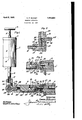
- Figure 1 is an elevation, partly in section, of a greasing apparatus constructed in accordance with my invention, the cup of which is shown as connected with a spring shackle of an automobile.
- Fig. 2 is a fragmental axial section inone horizontal axial plane, of the flexible tube and the swivel joint, the flexible tube and its swivel member being turned to-the horizontal plane of the swivel element of the adapter.
- Fig. 3 vis a fragmental ⁇ sectional detail showing a modified form in which the grease cup element is an integralp'art of the bearing.
- liquid, under pressure which is shown as comprising a cylindrical container 2; a removable and-replaceable c ap 3; a plunger 4; a plunger' stem 5 for threaded' connection with the cap 1 designates a source of grease, or other and having anoperating handle-6 and an outlet 7, in the form of a threaded nipple.
- a tube 8 Secured to the container, as by threading 1 to the outlet nipple, is a tube 8 and carried at the free end of the tube is a coupling element, which will hereinafter be referred-to as the adapter 9, for connecting the tube with the grease duct 10' of a bearing.
- the bearing as the spring shackle bearing of an automobile having the recited grease duct formed as an axial bore in the shackle bolt 11, which connects the V A withstanding relatively hard and rough usage I prefer to construct it of metal and in order to provide iiexibility in the tube for selective relative angularity between the adapter and the source ofgrease supply, I provide an all metal swivel 16, between the tube and adapter, having its one part, or arm, 17 threaded to the tube and its other part, or arm, 18 thread- Y ed to theadapter.
- a bore 23 of substantially the diameter of the bore 22, which extends in adirection toward the shank and only a relatively short distance from the transverse bore.
- a bore 24 of greater diameter than the bore 23 n leads from the inner, or shank, end of the cup to provide communication between the bore 23 and the duct 10 of the shackle and 'at its meetin point with the bore ⁇ 23 forms a seat 25 for t e ball of a ,check valve 26, comprising a spring which occupies the bore24 and. impin es the ball to hold it normally seated or c osed and which spring is held in the bore as by peening, or burring, the end of the bore as at 27.
- Theadapter 9 is b preference constructed as a metallic unit o cylinder shape, havingat its one end means such as threads 28 for connection with the tube 8, or more specilically to the arm 18v of the swivel 16, and at its opposite end with a bore 29, which is smooth and dimensioned to exactly lit over the cup, and is open at the outer end of the adapter.
- a bore 30providin ⁇ g Leading from the inner end of the bore 29 and opening at the peripheryof the adapter is a bore 30providin ⁇ g for the escape of air trapped during the placement of the adapter over the cup and for clearance of fouling matter lodged either on the cup Aor in the bore of theadapter.
- annular reduction, or neutralizing chamber 31 which communicates with the vtube 8 through bores 32, 33 and 34 formed in the adapter body.
- the arm 17 hasl formed in its one end a threaded bore 35.to receive the threaded end of thetube 8 leadingfrom which is a longitudinal bore 36 and leadin from the bore 36 is a right angled bore 3g that receives a pivot 38 bearing threads at each end and adapted to support thearm 18 and a securing nut 39 and 1n which pivot is a bore 40 having a right ⁇ angled branch 41.
- ⁇ In the arm 18 is an annular chamber 42 .for communication with the branch of the bore inthe pivot and leading away from the chamber at a right angle is a bore 43 for communication with the adapter.
- This form of swivel acts freely at all times and is not subject to binding at times when there is relatively high liquid ressures therein..
- cup 15 is formed as an 1ntegral part of the shackle bolt 11 and its operation and relation to the adapter is identical with the form shown in Fig. 1.
- Lubricating scribed comprising a substantially cylindrical nipple havingl a duct extendmg a portion of the lengt and opening in the side thereof, a unitary cylindrical coupling ⁇ memapparatus of the class de- ⁇ ber having an axial bore in onevend thereof .adapted to receive the cylindrical portion of said nipple, a latera ⁇ port at the lnner end' of'said. bore opening; to the atmosphere, and a grease conductin-g duct communicating with said bore at a point adjacent that taken by the opening in said nipple when the coupling is force over said nipple.
- a lubricant receivin nipple havin means for attachment to a earing, and wardl projecting portion a grease passageway ormed in sald nipple and openin in the side thereof
- a unitary coupling mem er said coupling member having a bore longer than the cylindrical portion of said nippleand adapted to'receive and make a lubricant tight fit therewith, a port at the inner end o said bore opening to the atmosphere, an annular'enlargement at the mid portion of said bore and a lubricant duct therein communicating with said annular enlargement of said bore and with a lubricant conduit.
Landscapes
- Engineering & Computer Science (AREA)
- General Engineering & Computer Science (AREA)
- Mechanical Engineering (AREA)
- Pivots And Pivotal Connections (AREA)
Description
April 5, 1932- v c. R. BUCHE-r I 1,852Q001A l GREASING APPARATUS Filed oct. 19. 1927 W K 1 l /mAM/X umass Y 9W. y
' 15x-aww@ Patented Apr. 5, 1932 UNITED STATES CONRAD RIBUCHET, OF LONG BEACH, CALIFORNIA, ASSIGNOR, BY ASSIGNMENTS,
vPATENT OFFICE TO ALEMITE CORPORATION, A. CORPORATION F DELAWARE GBEASING APPARATUS This invention relates to the class of greasing devices for supplying grease, or heavy lubricant, under pressure, to grease cups, or machine bearings, and has been especially designed for 4use in greasing automobiles.
There are two general types of such de-V vices, one of which requires a mechanicall locking means in the connection between the greasing device and the cup of the bearing to effect and maintain a leak proof seal in the grease line which is' the source of much annoyance andA loss of time due to fouling by foreign matter; and, the other of which requires that the greasing device be accurately.
tted and manually held to effect and main- 'tain a working connection 'during the greasing operation.
An object of my invention is to provide means, affording simple connection between a greasing device and a greasecup, which automatically'acts to effect and maintain a sealed mechanical fit and obviates the requirement for either a mechanical lock or manual holding of the greasing device during operation.
Another object is to provide a connection, between a greasing device and a grease cup,
in which a simple relative tting of parts, to effect mechanical connection, frees the related surfaces. of the iitted parts of foreign matter so that upon` final and full fitting of the parts, the grease line between the device and the cup will be fully open and rid of fouling matter.
l A broadly new,'basic and pioneer feature of the invention is a pressure neutralizer, in a grease line comprising separable parts, acting to overcome a tendency of the parts to separate during operation and to obviate 'requirement for mechanicallyl locking or manually holding the parts.
Another broadly new, basic and pioneer feature is a coupling, for separable parts of a grease line, comprising telescopically related elements, each ofV which includes a portion of the grease line and a lateral branch of the grease line opening to the perimeter of the elem'ent so that upon a fitting of the elements to effect communication between the two portions of the grease line .the joining surfaces of the two parts be freed from foreign matter tendlng to clog the grease line.
Advantages incident to the invention are automatic holding and self cleaning of the coupled parts of a grease line.
Other objects, advantages and features of invention may appear from the accompanying drawings, the subjoined detailed description and the appended claims.
The accompanying drawings illustrate the invention.
Figure 1 is an elevation, partly in section, of a greasing apparatus constructed in accordance with my invention, the cup of which is shown as connected with a spring shackle of an automobile.
Fig. 2 is a fragmental axial section inone horizontal axial plane, of the flexible tube and the swivel joint, the flexible tube and its swivel member being turned to-the horizontal plane of the swivel element of the adapter.
Fig. 3 vis a fragmental `sectional detail showing a modified form in which the grease cup element is an integralp'art of the bearing.
liquid, under pressure, which is shown as comprising a cylindrical container 2; a removable and-replaceable c ap 3; a plunger 4; a plunger' stem 5 for threaded' connection with the cap 1 designates a source of grease, or other and having anoperating handle-6 and an outlet 7, in the form of a threaded nipple.
Secured to the container, as by threading 1 to the outlet nipple, is a tube 8 and carried at the free end of the tube is a coupling element, which will hereinafter be referred-to as the adapter 9, for connecting the tube with the grease duct 10' of a bearing. I have arbitrarily shown the bearing as the spring shackle bearing of an automobile having the recited grease duct formed as an axial bore in the shackle bolt 11, which connects the V A withstanding relatively hard and rough usage I prefer to construct it of metal and in order to provide iiexibility in the tube for selective relative angularity between the adapter and the source ofgrease supply, I provide an all metal swivel 16, between the tube and adapter, having its one part, or arm, 17 threaded to the tube and its other part, or arm, 18 thread- Y ed to theadapter.
Theadapter 9, is b preference constructed as a metallic unit o cylinder shape, havingat its one end means such as threads 28 for connection with the tube 8, or more specilically to the arm 18v of the swivel 16, and at its opposite end with a bore 29, which is smooth and dimensioned to exactly lit over the cup, and is open at the outer end of the adapter. Leading from the inner end of the bore 29 and opening at the peripheryof the adapter is a bore 30providin`g for the escape of air trapped during the placement of the adapter over the cup and for clearance of fouling matter lodged either on the cup Aor in the bore of theadapter. Within the length of the bore and at a pointintersecting the transverse bore 22 of the cup, as when seated in the adapter, is an annular reduction, or neutralizing chamber 31, which communicates with the vtube 8 through bores 32, 33 and 34 formed in the adapter body.
In the construction of the swivel 16 I employ as a connection between the two parts,v
or arms 17 and 18, a sealed leak proof joint freed from end thrusts substantially similar to the joint between the adapter and cup. As shown in Fig. 2, the arm 17 hasl formed in its one end a threaded bore 35.to receive the threaded end of thetube 8 leadingfrom which is a longitudinal bore 36 and leadin from the bore 36 is a right angled bore 3g that receives a pivot 38 bearing threads at each end and adapted to support thearm 18 and a securing nut 39 and 1n which pivot is a bore 40 having a right `angled branch 41.
` In the arm 18 is an annular chamber 42 .for communication with the branch of the bore inthe pivot and leading away from the chamber at a right angle is a bore 43 for communication with the adapter. This form of swivel acts freely at all times and is not subject to binding at times when there is relatively high liquid ressures therein..
In Fig. 3 the cup 15 is formed as an 1ntegral part of the shackle bolt 11 and its operation and relation to the adapter is identical with the form shown in Fig. 1.
While I have designated my device as a greasing apparatus and have stressed its advantageous usein connection with the greasingl of bearings, I inno sense wish to be understood as limiting the use otA my mvent1on to such single purpose, as I have found -it to be highly advantageous in the flushing p f bearings by a cleaning fluid ysuch as gasoine.
I claim:
1. Lubricating scribed, comprising a substantially cylindrical nipple havingl a duct extendmg a portion of the lengt and opening in the side thereof, a unitary cylindrical coupling `memapparatus of the class de-` ber having an axial bore in onevend thereof .adapted to receive the cylindrical portion of said nipple, a latera` port at the lnner end' of'said. bore opening; to the atmosphere, and a grease conductin-g duct communicating with said bore at a point adjacent that taken by the opening in said nipple when the coupling is force over said nipple.
2. In high pressure lubricating apparatus,
the combination of a lubricant receivin nipple havin means for attachment to a earing, and wardl projecting portion, a grease passageway ormed in sald nipple and openin in the side thereof, a unitary coupling mem er, said coupling member having a bore longer than the cylindrical portion of said nippleand adapted to'receive and make a lubricant tight fit therewith, a port at the inner end o said bore opening to the atmosphere, an annular'enlargement at the mid portion of said bore and a lubricant duct therein communicating with said annular enlargement of said bore and with a lubricant conduit.
In testimony whereof, I have hereunto set my hand at Los An eles, California, this 7th day of October, 192g?. l lCONRAD R. BUCHET.
aving a smooth cylindrical outlll . ISU
Priority Applications (1)
| Application Number | Priority Date | Filing Date | Title |
|---|---|---|---|
| US227234A US1852001A (en) | 1927-10-19 | 1927-10-19 | Greasing apparatus |
Applications Claiming Priority (1)
| Application Number | Priority Date | Filing Date | Title |
|---|---|---|---|
| US227234A US1852001A (en) | 1927-10-19 | 1927-10-19 | Greasing apparatus |
Publications (1)
| Publication Number | Publication Date |
|---|---|
| US1852001A true US1852001A (en) | 1932-04-05 |
Family
ID=22852310
Family Applications (1)
| Application Number | Title | Priority Date | Filing Date |
|---|---|---|---|
| US227234A Expired - Lifetime US1852001A (en) | 1927-10-19 | 1927-10-19 | Greasing apparatus |
Country Status (1)
| Country | Link |
|---|---|
| US (1) | US1852001A (en) |
Cited By (1)
| Publication number | Priority date | Publication date | Assignee | Title |
|---|---|---|---|---|
| US2950895A (en) * | 1958-05-19 | 1960-08-30 | Edwin A Anderson | Pressure balanced fluid pressure connector |
-
1927
- 1927-10-19 US US227234A patent/US1852001A/en not_active Expired - Lifetime
Cited By (1)
| Publication number | Priority date | Publication date | Assignee | Title |
|---|---|---|---|---|
| US2950895A (en) * | 1958-05-19 | 1960-08-30 | Edwin A Anderson | Pressure balanced fluid pressure connector |
Similar Documents
| Publication | Publication Date | Title |
|---|---|---|
| US2423069A (en) | Swivel attachment for couplers | |
| US1117762A (en) | Coupling for hose and the like. | |
| US2101938A (en) | Lubricated swivel pipe joint | |
| US1852001A (en) | Greasing apparatus | |
| US1948503A (en) | Flow control fitting | |
| US2061086A (en) | Lubricating apparatus | |
| US1883273A (en) | Lubricating system | |
| US1580618A (en) | Nozzle for force-feed lubricators | |
| US1944124A (en) | Swivel coupling joint | |
| US1859251A (en) | Coupling | |
| US2554002A (en) | Check valve | |
| US1929854A (en) | Coupling | |
| US1401765A (en) | Lubricating system | |
| US1865932A (en) | Pressure coupling for lubrication | |
| US2175867A (en) | Valve | |
| US1572073A (en) | Bolt adapter for lubricating purposes | |
| US2272636A (en) | Lubricating attachment | |
| US1553184A (en) | Valved coupling | |
| US1703278A (en) | Lubricating system | |
| US1943326A (en) | Fluid conduit terminal | |
| US1874541A (en) | Lubricating device | |
| US1828934A (en) | Lubricating apparatus for automobiles and the like | |
| US2079361A (en) | Lubricating apparatus | |
| US1744793A (en) | Tool for use in high-pressure lubricating systems | |
| US2087085A (en) | Lubricating apparatus |