US1851997A - Shock absorbing mechanism - Google Patents
Shock absorbing mechanism Download PDFInfo
- Publication number
- US1851997A US1851997A US372108A US37210829A US1851997A US 1851997 A US1851997 A US 1851997A US 372108 A US372108 A US 372108A US 37210829 A US37210829 A US 37210829A US 1851997 A US1851997 A US 1851997A
- Authority
- US
- United States
- Prior art keywords
- casing
- shock absorbing
- shoulders
- wedge
- locking
- Prior art date
- Legal status (The legal status is an assumption and is not a legal conclusion. Google has not performed a legal analysis and makes no representation as to the accuracy of the status listed.)
- Expired - Lifetime
Links
- 230000007246 mechanism Effects 0.000 title description 28
- 230000035939 shock Effects 0.000 title description 25
- 230000003247 decreasing effect Effects 0.000 description 2
- 229940077232 absorbine Drugs 0.000 description 1
- 239000008330 absorbine Substances 0.000 description 1
- 230000000295 complement effect Effects 0.000 description 1
- 210000005069 ears Anatomy 0.000 description 1
- 230000005484 gravity Effects 0.000 description 1
- 238000003780 insertion Methods 0.000 description 1
- 230000037431 insertion Effects 0.000 description 1
- 238000000034 method Methods 0.000 description 1
- 230000004048 modification Effects 0.000 description 1
- 238000012986 modification Methods 0.000 description 1
- 238000005096 rolling process Methods 0.000 description 1
Images
Classifications
-
- B—PERFORMING OPERATIONS; TRANSPORTING
- B61—RAILWAYS
- B61G—COUPLINGS; DRAUGHT AND BUFFING APPLIANCES
- B61G9/00—Draw-gear
- B61G9/04—Draw-gear combined with buffing appliances
- B61G9/10—Draw-gear combined with buffing appliances with separate mechanical friction shock-absorbers
Definitions
- This invention relates to improvements in shock absorbing mechanisms of the typeespecially adapted for use in draft riggings for railway rolling stock and particularly to that type comprising a casing containing a spring resisted plunger or friction wedge means through which bufng Vand pulling shocks are transmitted.
- the principal object of my invention is to provide a shock absorbing mechanism, of the above type, with novel, eiicient andinexpensive means for maintaining the plunger assembled with the other parts of the mechanism.
- Another object of my invention is to provide a shock absorbing mechanism, of the above type, with locking means adapted to be moved into and out of a position to lock with the casing and plunger when the plunger is moved inwardly a predetermined distance relative to the casing in assembling or disassembling the mechanism.
- a further object of my invention' resides in the method of locking the shock transmitting plunger of a shock absorbing mechanism, of the above type, in assembled relation to the other parts of the mechanism which consists in first forcing the plunger inwardly a predetermined distance against the pressure of the shock absorbing springs, then inserting a locking member ina direction longitudinally of the mechanism between the plunger and casing, said member being forced outwardly in a directionl toward the casing as it is so inserted and then relieving the compressing force on the plunger to permit the pressure of the shock absorbing springs to move said plunger into locking engagement with the locking member and the looking member into locking engagement with the casing.
- Figure l is a horizontal longitudinal sectional view of a railway draft rigging embodying my invention
- Fig. 2 is vertical longitudinal sectionalview of the friction shock absorbing mechanism in its assembled condition
- Fig. 3 is an 1929. Serial N0. 372,108.
- the reference characters 1, 1 indicate the usual. spaced center or draft' sills of a railway car, to ,which are secured the usual front draft lugs 2, 2 and rear draft lugs 3, 3. y
- the reference character 4 indicates the inner end of the drawbar to which is operative-V ly connected the usual yoke 5.
- yoke 5 Disposed within the yoke 5 is my improved friction shock absorbing mechanism and a front follower plate 6, all of which are supported inthe usual manner by a strap or-plate 7 detachably secured to the sills, 1, 1, so that the follower plate engages ⁇ the fronti draft lugs 2. 2 and the rear end portionof the shock absorbing mechanism engages the rearldraft lugs3,3.jy Y
- Mv improved friction shock absorbing mechanism may comprise a hollow rectangular casing having side walls 8 ⁇ top and bottom walls 9 and a rear end wall 10.
- the forward end ofthe casing is open and contains groups of alternated friction plates 11 and 12 which are disposed at opposite sides ofpa wedging of the plates being stopped by their engagement with shoulders 17, 17 on the walls 9.
- TheV wedging mechanism comprises longitudinally disposed wedge blocks 18 and 19 having opposed wedging faces adapted to engage corresponding wedging faces of wedge blocks or shoes 20 disposed at opposite-sides ofthe wedge blocks l18 and 19.
- a followeror spring plate 21 Disposed within the casingis a followeror spring plate 21 which, at one side, engages the inner ends of the movable friction plates 12 and also the wedge block 19, the other side Iof the plate 21 being engaged by four springs 22.
- the wedge Vblock 18 is acted upon by springs V23 and 24 through the medium of a follower Y25, which extends through an opening in the spring plate 21, and a spring plate 26 which is interposed between the tops 'of thesprings 23 and V24 and the inner yend of the ,follower l25.
- groovesf27, v27 for the reception'of locking members 28, 28.
- Ea'chof these grooves extends longitudinally of the wedge block, from the forward end thereof to any vsuitable ,point rearwardly of the forward end, 'and throughout its length varies in depth, from its deepest portion at its outer end, toits shallowest portionjat its inner end.
- the inner end. of each slot is 'defined byrra shoulder 29.
- the outer end face 30 ofthe wedge block,'eac'hof the grooves 27 is widened to form shoulders 31, 31, the upper 'ends of n the locking members 28 being broken away in Fig. 2 to 'clearly Vshow vthese shoulders.
- Each lockingl member -'28 comprises a portion "32 which is of a width slightly less 'than the width of :the groove 27 and has an outer straightsurface 33 andan inner sloping surface-34 which corresponds tothe slope ofthe bottom of the grooves 27. yits outer end the locking member is provided with 'ears or lugs Y35 whichproject foutwardly from opposite 'sides Y'ofthe member, and at its inner end.
- lug 36 which projects out wardly'beyondthe plane 'of the surface 33.
- the casing In assembling the friction shock absorbing mechanism the casing is preferably placed in a vertical position as shown in Figs. 2 to 5 inclusive and the springs 22, 23, and 24, spring plates 26 and 21, stationary plates 11, movable plates 12 and follower 25 are mounted in the casing through -the open forward end thereof in theorder named.
- the wedge block 18 is now'inserted through the forward end ⁇ of ⁇ the casing and seats on the outer end of the follower 25. Since all of the springs in vrthe casing are expanded to their free length the parts of the Ymechanism .will be in the positions shown in Fig. l. From this view'it will be .noted that the wedge block 18 wil'lbe in such a forward position relative to the casing that the locking membersl cannot be moved to ⁇ their locking positions.
- Vhenthe shoclrabsorbing mechanism is aslShdV asn described andthe mechanism is embodied in a railway draft rigging as shown in Fig. l, the outer ends of the locking members 28, which are flush with the surface 30, are engaged by the follower plate and due to this, outward movement of the locking members relative to the wedge blocl when the relative positions of the wedge block 18 and casing are changed due to service shocks is prevented.
- ln F 'T a modication of the invention is illustrated in w iich the lugs on the locking members only are engaged by the wedge block in locking the block in operative position.
- a friction shock absorbing mechanism the combination with a casing, of lugs within the forward end of said casing, spring resisted friction means mounted in and engaging the forward end of the casing, said friction means including pressure exerting wedge block having grooves formed in two opposite sides thereof, the bottoms of said grooves diverging rearwardly from the forward end of the wedge block, members cooperating with said ings and wedge bloeit for maintaining said wedge block assembled with the casing, said members being insertable in said grooves and between the wedge block and casing from the forward end of the casing and wedge block when said wedge block is moved inwardly a nredetermined distance relativek to the casing, said diverging bottoms of the grooves forcing said members apart into positions to cooperate with said lugs as said members are beinginserted.
- a casing having an open end and instanding ribs across two of its side walls adjacent such end, shock-absorbing means within the casing including a follower-engaging thrust member having longitudinally .channeled side walls fitting between the ribs, such channelsextending from the outer end of the member and terminating short of its inner end and 'bein of greater depth at theirV outer than at their inne' ends, loclingbars housedwithin the channels and having rib-engaging lugs at their inner ends, and inwardly facing shoulc ers at their outer ends engageable with complementary shoulders on the thrust member'.
- Li. ln a draft gear in combination, a Vcasing having an open end and instandingribs across two of its side Vwalls adjacent such end, shoclr-absorbingmeans within the cas-l ing including a Ifollower-engaging thrust member having longitudinally channeled side walls fitting betweenthe ribs, such channels extending from the outer end of the member and terminating short of its inner end and being of greater depth at their outer than at their inner ends, locking bars housed within the channels and having rib-engaging lugs at their inner ends, and-means for preventing lateral movement of the bars within the channels.
- a Ifollower-engaging thrust member having longitudinally channeled side walls fitting betweenthe ribs, such channels extending from the outer end of the member and terminating short of its inner end and being of greater depth at their outer than at their inner ends, locking bars housed within the channels and having rib-engaging lugs at their inner ends, and-means for preventing lateral movement of the bars within the channels.
- a shock absorbing mechanism in combination, a casing having an open end and inwardly facing shoulders adjacent thereto, a thrust element projecting into the casing and having rearwardly facing lateral shoulders adjacent to its inward end, and lateral faces diverging from its outer end and leading to its shoulders, shock-absorbing elements housed within the casing and cooperating with the thrust member, and retaining bars having bearing on the diverging faces and engageable with the shoulders of the thrust element and casing.
- a shock absorbing mechanism in combination, a casing having an open end and inwardly facing shoulders adjacent thereto, a thrust element projecting into the casing and having rearwardly facing lateral shoulders adjacent to its inward endand lateral faces diverging from its outer end and Y leading to its shoulders, shock absorbing elements housed within the casing and cooperating with the thrust member, retaining bars having bearing on the diverging faces and cngageable with the shoulders of the thrust element and casing, and means for holding th bars in contact with the thrust element.
- a casing having anV open end and rearwardly facing shoulders adjacent thereto, a. thrust element projecting into thel ln a shock absorbing mechanism, in l casing and having longitudinalchannels of gradually decreasing depth inwardly and shoulders facing the inner end of the channels7 retaining bars seated Within the channels and having lateral shoulders engageable With the casing shoulders, and shock absorbing elements Within the casing and cooperating with the thrust element.
- a shock absorbing mechanism incomhination, a casing having an open end and rearwardly facing shoulders adjacent thereto, a thrust element projecting into the casing and having longitudinal ⁇ channels of Y gradually decreasing depth inwardly and Shoulders 'fac-ing the inner end of the channels, retaining bars seated Within the Channels and having lateral shoulders engageaole with the easing shoulders, means for holding thebars Within the channels, and shock ab- 26 sorbing elements Within the casing and cooperating With the thrust element.
Landscapes
- Engineering & Computer Science (AREA)
- Mechanical Engineering (AREA)
- Vibration Dampers (AREA)
Description
April 5, 1932. l G. W. WlLDlN 1,851,997
SHOCK ABsoRBING MECHANISM Filed June 19, 1929 2 sheets-sheet 1 INVENTOR GEORGE W. WILDIN ATTOR EY Patented Apr. 5, 1932 'miran sr'iras GEORGE W. WILDN, 0F PITTSBU'RGI-I,4 PENNSYLVANIA, ASSIGNOR," BY MESNE ASSIGN` kasics MENTS, T0 CARDWELL WESTINGHOUSE CGMPANY, OF CHICAGO, ILLINOISQA COR- PORATION OF DELAWARE siioox ABsoRBine MEcHAmsr/ i Y Application led June 19,
This invention relates to improvements in shock absorbing mechanisms of the typeespecially adapted for use in draft riggings for railway rolling stock and particularly to that type comprising a casing containing a spring resisted plunger or friction wedge means through which bufng Vand pulling shocks are transmitted. l
The principal object of my invention is to provide a shock absorbing mechanism, of the above type, with novel, eiicient andinexpensive means for maintaining the plunger assembled with the other parts of the mechanism.
Another object of my invention is to provide a shock absorbing mechanism, of the above type, with locking means adapted to be moved into and out of a position to lock with the casing and plunger when the plunger is moved inwardly a predetermined distance relative to the casing in assembling or disassembling the mechanism. y
A further object of my invention'resides in the method of locking the shock transmitting plunger of a shock absorbing mechanism, of the above type, in assembled relation to the other parts of the mechanism which consists in first forcing the plunger inwardly a predetermined distance against the pressure of the shock absorbing springs, then inserting a locking member ina direction longitudinally of the mechanism between the plunger and casing, said member being forced outwardly in a directionl toward the casing as it is so inserted and then relieving the compressing force on the plunger to permit the pressure of the shock absorbing springs to move said plunger into locking engagement with the locking member and the looking member into locking engagement with the casing. y
Other objects and advantages will appear in the following more detailed description o f my invention.
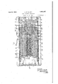
In the accompanying drawings Figure l is a horizontal longitudinal sectional view of a railway draft rigging embodying my invention; Fig. 2 is vertical longitudinal sectionalview of the friction shock absorbing mechanism in its assembled condition; Fig. 3 is an 1929. Serial N0. 372,108.
In .the drawings, the reference characters 1, 1 indicate the usual. spaced center or draft' sills of a railway car, to ,which are secured the usual front draft lugs 2, 2 and rear draft lugs 3, 3. y
The reference character 4 indicates the inner end of the drawbar to which is operative-V ly connected the usual yoke 5.
Disposed within the yoke 5 is my improved friction shock absorbing mechanism and a front follower plate 6, all of which are supported inthe usual manner by a strap or-plate 7 detachably secured to the sills, 1, 1, so that the follower plate engages `the fronti draft lugs 2. 2 and the rear end portionof the shock absorbing mechanism engages the rearldraft lugs3,3.jy Y
Mv improved friction shock absorbing mechanism may comprise a hollow rectangular casing having side walls 8` top and bottom walls 9 and a rear end wall 10. The forward end ofthe casingis open and contains groups of alternated friction plates 11 and 12 which are disposed at opposite sides ofpa wedging of the plates being stopped by their engagement with shoulders 17, 17 on the walls 9.
TheV wedging mechanism comprises longitudinally disposed wedge blocks 18 and 19 having opposed wedging faces adapted to engage corresponding wedging faces of wedge blocks or shoes 20 disposed at opposite-sides ofthe wedge blocks l18 and 19.
Disposed Within the casingis a followeror spring plate 21 which, at one side, engages the inner ends of the movable friction plates 12 and also the wedge block 19, the other side Iof the plate 21 being engaged by four springs 22.
The wedge Vblock 18 is acted upon by springs V23 and 24 through the medium of a follower Y25, which extends through an opening in the spring plate 21, and a spring plate 26 which is interposed between the tops 'of thesprings 23 and V24 and the inner yend of the ,follower l25.
Formed in the top and rbottom sides of the wedge 'block 18, are groovesf27, v27 for the reception'of locking members 28, 28. Ea'chof these grooves, extends longitudinally of the wedge block, from the forward end thereof to any vsuitable ,point rearwardly of the forward end, 'and throughout its length varies in depth, from its deepest portion at its outer end, toits shallowest portionjat its inner end. 'The inner end. of each slot is 'defined byrra shoulder 29. ln the outer end face 30 ofthe wedge block,'eac'hof the grooves 27 is widened to form shoulders 31, 31, the upper 'ends of n the locking members 28 being broken away in Fig. 2 to 'clearly Vshow vthese shoulders.
Each lockingl member -'28 comprises a portion "32 which is of a width slightly less 'than the width of :the groove 27 and has an outer straightsurface 33 andan inner sloping surface-34 which corresponds tothe slope ofthe bottom of the grooves 27. yits outer end the locking member is provided with 'ears or lugs Y35 whichproject foutwardly from opposite 'sides Y'ofthe member, and at its inner end.
is provided with a lug 36 which projects out wardly'beyondthe plane 'of the surface 33.
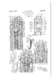
When 'theshock 'absorbing mechanism is assembled as shown Vin Figs. 1, 2 and 3 the locl'ring members 28, 28 substantially fill the grooves 27,127, the lugs 36, 3G-engage the shoulders 15, 15 `of the block 18, andthe lugs 35 are seated fon the shoulders 531 'of the rcasing within the widened portions of vthe grooves so 'that the Vwedge block 18 will tbe held against undue outward ymovement 2by the engagement of the shouldersf29 'of vthe wedge bloclr withthe undersides of the lugs 36. Sincethe'lugs 35 ofthe'members28 are seated ein fthe Vgrooves 27 the outer ends of these members jare prevented from moving outwardly.relativeto-the wedge block in directi'onslacros's the casinglthus eliminating'the possibility of the binding of the members 2 agai'n'st"thel casing4 and also preventing! undue vibrations of the members when the mechanism is in service.
In assembling the friction shock absorbing mechanism the casing is preferably placed in a vertical position as shown in Figs. 2 to 5 inclusive and the springs 22, 23, and 24, spring plates 26 and 21, stationary plates 11, movable plates 12 and follower 25 are mounted in the casing through -the open forward end thereof in theorder named. The wedge block 18 is now'inserted through the forward end `of `the casing and seats on the outer end of the follower 25. Since all of the springs in vrthe casing are expanded to their free length the parts of the Ymechanism .will be in the positions shown in Fig. l. From this view'it will be .noted that the wedge block 18 wil'lbe in such a forward position relative to the casing that the locking membersl cannot be moved to `their locking positions.
After the several kparts of the lmechanism Y have been positioned as ust described, pressure is applied,\through the medium of Vany desired pressure exerting -means, to the outer end of the wedge bloclr'18, causing said block to move inwardly relative to the casing and against thepressure ofthe springs'22, 23 and 24C. After the wedge block has thus been moved inwardly a short distance the distance between the inner surface of `veach of `the thickened portions 14 of the casing Vand the bottom `of the groove 27 `will be sucient 'to permit of the insertion of the `inner end of the locking member. IWith both ofthe lo,cl ing members thus positioned and the lwedge block Ybeing pressed rearwardly the locking members will continueto move i-nwardlydue to the force of gravity and when the wedge hasb'een movedto vthe positionshownlin Fig. 5,'.the locking members will drop into positions as shown 4in dot anddash lines in this figure, in which positions the 'inner 'ends of locking members engage the shoulders 29 of the wedge :block and the lugs :35 engage the shoulders `31 of the wedge block. Pressure on the wedge Vbloclr is 'now relieved and .the pressure of the springs in the casing move the wedge block forward, and `when -the lugs 36 on the locking lmembers come intofen'gagement vwith the shoulders 15 ofthe casing, the wedge block will be positively stopped against further outward movement 'as shown in Fig. 2.
Instead of permitting the 'locking members to drop into place by the Aforce offgravity as justdes'cribed, the wedge bloclrm'ay'be forced. rearwardly to theposition Yshown in Fig.
andthe lookin g'members then inserted.
liVhen it is desired to. remove Athe wedge block 18 from the mechanism, said block Y18 is forced rearwardly tothe position .shown .in Fig. 5 when, it willbe seen, the lockingmembers may be easily removed.
Vhenthe shoclrabsorbing mechanism is asl sembledV asn described andthe mechanism is embodied in a railway draft rigging as shown in Fig. l, the outer ends of the locking members 28, which are flush with the surface 30, are engaged by the follower plate and due to this, outward movement of the locking members relative to the wedge blocl when the relative positions of the wedge block 18 and casing are changed due to service shocks is prevented.
ln F 'T a modication of the invention is illustrated in w iich the lugs on the locking members only are engaged by the wedge block in locking the block in operative position.
ln 8 a further modification has been illustrated in which the lugs 35 of the locking members are out of engagement with the shoulders 3l and the inner end portions of the members are engaged by the wedge block in locking the bloc f in operative position.
it will benoted from the foregoing description that l have provided simple and enicient means for locking the wedge blocl, of a friction shock absorbing mechanism, in its operative position, which means may be readily inserted from the front end of the casing of the mechanism while the wedge block is in the casing.
While several illustrative embodiments of the invention have been described in detail, it is not my intention to limit its scope to these embodiments or otherwise than by the terms of the appended claims.
Having now described my invention, what l claim as new and desire to secure by Letters Patent, is:
l. In a friction shock absorbing mechanism, the combination with a casing, of lugs within the forward end of said casing, spring resisted friction means mounted in and engaging the forward end of the casing, said friction means including pressure exerting wedge block having grooves formed in two opposite sides thereof, the bottoms of said grooves diverging rearwardly from the forward end of the wedge block, members cooperating with said ings and wedge bloeit for maintaining said wedge block assembled with the casing, said members being insertable in said grooves and between the wedge block and casing from the forward end of the casing and wedge block when said wedge block is moved inwardly a nredetermined distance relativek to the casing, said diverging bottoms of the grooves forcing said members apart into positions to cooperate with said lugs as said members are beinginserted.
2. ln a draft 'ear in combination a Casin b v Y 2 i naving an open end instanding ribs across two of its side walls adjacent such end, shockabsorbing means within the casing including a follower-eng ging thrust member having longitudinally channeled side walis .fitting between the ribs, sii-ch channels extending from the outer end of ne member and terminating short of its inner end and being of greater depth at their outer than at their inner ends, and locking bars housed within the channels and having rib-engaging lugs at their inner ends. Y
3. In a draft gear, in combination, a casing having an open end and instanding ribs across two of its side walls adjacent such end, shock-absorbing means within the casing including a follower-engaging thrust member having longitudinally .channeled side walls fitting between the ribs, such channelsextending from the outer end of the member and terminating short of its inner end and 'bein of greater depth at theirV outer than at their inne' ends, loclingbars housedwithin the channels and having rib-engaging lugs at their inner ends, and inwardly facing shoulc ers at their outer ends engageable with complementary shoulders on the thrust member'.
Li. ln a draft gear, in combination, a Vcasing having an open end and instandingribs across two of its side Vwalls adjacent such end, shoclr-absorbingmeans within the cas-l ing including a Ifollower-engaging thrust member having longitudinally channeled side walls fitting betweenthe ribs, such channels extending from the outer end of the member and terminating short of its inner end and being of greater depth at their outer than at their inner ends, locking bars housed within the channels and having rib-engaging lugs at their inner ends, and-means for preventing lateral movement of the bars within the channels.
5. ln a shock absorbing mechanism, in combination, a casing having an open end and inwardly facing shoulders adjacent thereto, a thrust element projecting into the casing and having rearwardly facing lateral shoulders adjacent to its inward end, and lateral faces diverging from its outer end and leading to its shoulders, shock-absorbing elements housed within the casing and cooperating with the thrust member, and retaining bars having bearing on the diverging faces and engageable with the shoulders of the thrust element and casing.
6. In a shock absorbing mechanism, in combination, a casing having an open end and inwardly facing shoulders adjacent thereto, a thrust element projecting into the casing and having rearwardly facing lateral shoulders adjacent to its inward endand lateral faces diverging from its outer end and Y leading to its shoulders, shock absorbing elements housed within the casing and cooperating with the thrust member, retaining bars having bearing on the diverging faces and cngageable with the shoulders of the thrust element and casing, and means for holding th bars in contact with the thrust element.
combination, a casing having anV open end and rearwardly facing shoulders adjacent thereto, a. thrust element projecting into thel ln a shock absorbing mechanism, in l casing and having longitudinalchannels of gradually decreasing depth inwardly and shoulders facing the inner end of the channels7 retaining bars seated Within the channels and having lateral shoulders engageable With the casing shoulders, and shock absorbing elements Within the casing and cooperating with the thrust element.
S. In a shock absorbing mechanism, incomhination, a casing having an open end and rearwardly facing shoulders adjacent thereto, a thrust element projecting into the casing and having longitudinal` channels of Y gradually decreasing depth inwardly and Shoulders 'fac-ing the inner end of the channels, retaining bars seated Within the Channels and having lateral shoulders engageaole with the easing shoulders, means for holding thebars Within the channels, and shock ab- 26 sorbing elements Within the casing and cooperating With the thrust element.
In testimony whereof I have hereunto set myy hand, this 8th' day of June, 1929.
, GEGRGE W. WILDIN.
@of Y
Priority Applications (1)
| Application Number | Priority Date | Filing Date | Title |
|---|---|---|---|
| US372108A US1851997A (en) | 1929-06-19 | 1929-06-19 | Shock absorbing mechanism |
Applications Claiming Priority (1)
| Application Number | Priority Date | Filing Date | Title |
|---|---|---|---|
| US372108A US1851997A (en) | 1929-06-19 | 1929-06-19 | Shock absorbing mechanism |
Publications (1)
| Publication Number | Publication Date |
|---|---|
| US1851997A true US1851997A (en) | 1932-04-05 |
Family
ID=23466741
Family Applications (1)
| Application Number | Title | Priority Date | Filing Date |
|---|---|---|---|
| US372108A Expired - Lifetime US1851997A (en) | 1929-06-19 | 1929-06-19 | Shock absorbing mechanism |
Country Status (1)
| Country | Link |
|---|---|
| US (1) | US1851997A (en) |
-
1929
- 1929-06-19 US US372108A patent/US1851997A/en not_active Expired - Lifetime
Similar Documents
| Publication | Publication Date | Title |
|---|---|---|
| US1851997A (en) | Shock absorbing mechanism | |
| US1862764A (en) | Friction shock absorbing mechanism | |
| US1290307A (en) | Shock-absorbing mechanism. | |
| US2146956A (en) | Friction shock absorbing mechanism | |
| US2421075A (en) | Friction shock absorbing mechanism | |
| US1694987A (en) | Shock absorber | |
| US1938881A (en) | Shock absorbing mechanism | |
| US2399110A (en) | Shock absorbing mechanism | |
| US1844234A (en) | Friction draft gear | |
| US1750455A (en) | Draft gear | |
| US3042224A (en) | Draft assembly | |
| US1968942A (en) | Friction shock absorbing mechanism | |
| US1758966A (en) | Friction shock-absorbing mechanism | |
| US1844197A (en) | Friction draft gear | |
| US1684539A (en) | Friction shock-absorbing mechanism | |
| US1763974A (en) | Railway draft rigging | |
| US1637149A (en) | Friction shock-absorbing mechanism | |
| US2492525A (en) | Friction shock absorbing mechanism for railway draft riggings | |
| US2471061A (en) | Friction shock absorbing mechanism | |
| US1846517A (en) | Friction shock absorbing mechanism | |
| US2897980A (en) | Draft mechanism | |
| US1897780A (en) | Friction shock absorbing mechanism | |
| US1882799A (en) | Friction shock absorbing mechanism | |
| US1831890A (en) | Friction draft gear | |
| US2149203A (en) | Cushioning mechanism |