US1851993A - Lister - Google Patents
Lister Download PDFInfo
- Publication number
- US1851993A US1851993A US446813A US44681330A US1851993A US 1851993 A US1851993 A US 1851993A US 446813 A US446813 A US 446813A US 44681330 A US44681330 A US 44681330A US 1851993 A US1851993 A US 1851993A
- Authority
- US
- United States
- Prior art keywords
- beams
- tractor
- axles
- wheels
- gauge
- Prior art date
- Legal status (The legal status is an assumption and is not a legal conclusion. Google has not performed a legal analysis and makes no representation as to the accuracy of the status listed.)
- Expired - Lifetime
Links
Images


Classifications
-
- A—HUMAN NECESSITIES
- A01—AGRICULTURE; FORESTRY; ANIMAL HUSBANDRY; HUNTING; TRAPPING; FISHING
- A01B—SOIL WORKING IN AGRICULTURE OR FORESTRY; PARTS, DETAILS, OR ACCESSORIES OF AGRICULTURAL MACHINES OR IMPLEMENTS, IN GENERAL
- A01B13/00—Ploughs or like machines for special purposes ; Ditch diggers, trench ploughs, forestry ploughs, ploughs for land or marsh reclamation
- A01B13/02—Ploughs or like machines for special purposes ; Ditch diggers, trench ploughs, forestry ploughs, ploughs for land or marsh reclamation for making or working ridges, e.g. with symmetrically arranged mouldboards, e.g. ridging plough
Definitions
- the present invention relates generally to agricultural implements and more particularly to a type of implement adapted for attachment to or to be carried by a motor driven l tractor so that when connected together the two function as a single power operated machine.
- my invention is concerned with the provision of an eiicient machine adapted particularly for use in preparing the seed bed andin planting cotton, although it is to be understood that it is also appllicable to corn or other listed crops as we
- the principal feature of my invention may be said to lie in the provision of an. iniproved arrangement of adjustable gauge wheels for regulating the operating depth of the ground working elements, whereby the gauge wheels may be so positioned relative to the tractor and'to the ground as to secure the best results for the particular operation performed by the implement at any one time.
- planting mechanism may be omitted during both the first ridging operation and the second ridging operation.
- the gauging of the depth for the furrow openers be done from the undisturbed ground surface for two reasons.
- the first is the obvious reason that it is possible to plow at a uniform depth with respect -to the ground surface only by gauging from the ground surface itself.
- the second reason is ⁇ that it is desirable not to have to shift the depth adjusting levers each time the implement is turned around at the end of the field to start the next rows.- Sincethe gauge wheel that is the landward wheel in traveling up the field, must necessarily run on the undisturbed land. becomes the furrow wheel when coming back, both wheels must gauge from the same level in order that it not be necessary to shift the position of the wheels at the end of the field. It is, of course, also necessary, for accurate gauging, that the gauge wheels be positioned as close as possible to the ground working tool.
- the gauge wheels For the first rldging operation I preferably space the gauge wheels so that they substantially clear the ridges thrown up by the furrow openers, the spacing being such, however, that the furrowed gauge wheel does not run into the adjacent furrow. In this manner the gauge wheelsf'gauge the depth of operation of the furrow openers substantially from the undisturbed ground.
- Figure 2 is an enlarged rear view showing the parts as arranged in Figure 1 and as employed in the second ridging operation, referred to above;
- Figure 3 is a top plan view of the machine as arranged in Figure 1, showing also, in dotted lines, the position of the depth gauging means adjusted for the first ridgingv operation;
- Figure 4 is a fragmentary side elevation showing the depth gauging means arranged forthe first ridging operation
- Figure 5 is a rear ⁇ view of the machine as arranged in Figure 4.
- Figure 6 is a detail of the lifting connection to the axle of the gauge wheels.
- FIGS 7 and 8 are enlarged detail views of the beam connecting means which serve to rigidly connect the beams of the furrow openers.
- the reference numeral 1 indicates generally the tractor having the customary drive wheels 2 and drive housings 3. Pivotally connected to the front of the tractor, as by a bar or shaft 5, are a plurality of longitudinally extending beams 6. The beams 6 are connected to the shaft 5 by means of links or arms 9 and at their rear ends the beams 6 curve downwardly for connection with the furrow openers 11. i i
- the usual planting mechanism is indicated by the reference numeral y15 and it is supported upon transversely extending bars 16 carried by brackets 18 which may be bolted to the drive housings 3.
- the longitudinally extending beams 6 are rigidly connected together at their rear ends by means of a transverse connecting melnber indicated in its entirety by the reference numeral 20.
- the member 20 comprises two I- beams 21 and 22 boltedtogether at their inner ends by two plate vmembers24 and 25, see Figures 7 and v8, and each of the plate members is made up of two plates as indicated in Figure -7.
- the outer plate. of each of the plate members 24 and v25 is adapted to fit .against the outer edges of the flanges of the I-beams while the inner plates of the plate members 24 and 25 are adapted to abut against *thev inner surfaces of the flanges of the I- beams 21 and 22.
- the plate members 24 and 25 areeach providedfwith four holes through which bolts 27 are adapted to be passed whereby the plate members 24 ⁇ -and 25 may be clamped or drawn up against the edges of the flanges ofthe I-beams 21 and 22.
- the adjacent ends of these flanges are apertured and'through theapertures bolts 29 are passed,
- the outer ends of the I-beams 21 and 22 are each provided with a depending bracket 33 secured thereto, as by ,welding or the like.
- the brackets 33 are each bolted to the corresponding beam 6 by bolts 35 as indicated in Figures 1 and 4.
- rllhe depth gauging mechanism is seen to ⁇ comprise a pair of gauge wheels 40 mounted v upon the inwardly turned horizontal portions of the crank axles.
- axles 42 have transversely extending portions 43 by which the crank axles 42 vare j ournaled upon the transverse connecting member 20. Adjacent the outer ends of the transverse member 20 are a number of'bearing brackets 45 secured thereto, as by welding, and
- brackets rotatably receive the crankaxles 42 whereby the rear ends of thebeams 6 may be supported.
- Collars47 are provided for the purpose of preventing undesired transverse displacement of the crank axles 42 in the bearing'brackets 45, and these collars 47 maybe secured to the crank axles 42 by set screws projecting or threaded Kinto. holes formed in the crank axles 42. preferably supply a number .of holes therefor, such as are indicatedin Figure 5 by the reference numeral 50, for a scribed.
- the manual means I have provided for advjusting the depth of operation of the furanism for retaining the levers 55 in any'- of ⁇ their adjusted positions.
- a link 56 is conpurpose later to be 'denected to the lever 55 at its forward end, f
- the levers 56 are each connect-ed to arms 57 bolted to an upwardly projecting lug 59 formed on or a part of a sleeve member 60.
- the sleeve member 60 extends laterally in both directions from the lug 59 and is yadapted to embrace the crank axle 42.
- the sleeve member Has a pair of capv axles 42 tobe secured t0 thesleeve members' 60 in eitherof two positions.
- crank lgauge wheels 40 One position ⁇ of the crank lgauge wheels 40 is shown in'full lines )in Fig-YV 12sV I axles 42 and the l;
- crank axles 42 are so adjusted as to bring the wheels 40 rearwardly of the furrow openers 11 and in their closest position, ⁇ that is, practically directly behind the drive wheels 2'so that they run on the ridges thrown up by the furrow openers 11, as indicated in Figure 2.
- 'VIhis is the position, it will be noted, for which the gauge wheels are 4adjustedwhen performing the second ridging operation.
- crank axles 42 and the gauging wheels 40 are positioned as shown in dotted .lines in Figure 3, that is, each of the crank axles are moved outwardly to space the gauge wheels 40 farther apart, the cap screws 63 being loosened to allow the crank axles to be moved relative to the sleeves 60 and the collars 47 being loosened to allow the crank axles to be moved outwardly relative to the bearing brackets 45 carried on the transverse connecting member 20.
- crank axles 42 are cranked from a rearwardly extending position as shown in Figure 1 to a forwardly extending position as shown in in Figure 4, thus bringing the gauge wheels 40 from a position behind the drive wheels to a position laterally adjacent them.
- the planting mechanism l5 During the first ridging operation it is preferable to detach the planting mechanism l5 and then subsequently attach the same for operation during the secondV ridging operation so that the planting is done at the latter time.
- bumpers 70 comprise a U- shaped bar the ends of which are bolted to the drive housings 3.
- the intermediate portions of the U-shaped bumpers 7 O extend in a vertical plane as indicated in Figure 2 and in a position to bear against the outer sides of the beams 6 to prevent them from swerving laterally. l.
- the gauge wheels When performing the first ridging operavtion the gauge wheels are positioned as shown in' Figure 5, and in this operation the rows or furrows are made consecutively across the field, that is, the implement is driven back and forth across the field, and when going in one direction the left hand gauge wheel 40 will run close to the adjacent furrow, see Figure 5, and in going in the other direction the right hand wheel will be the one running close to the adjacent furrow.
- the opera! or plants two rows and then skips two rows, taking the next two, and so on.
- the operator plants rowsrl and 2, 5 and 6, 9 and 10, and so on, and after he has covered the field in this manner, taking alternate pairs of rows, he starts back and opens up and plants in the rows he left, that is, rows 3 and 4, 7 and 8, and so on.
- the drive wheels of the tractor run in the bottoms of the old furrows, as indicated in Figure 2, but in planting rows 3 and 4, etc., the drivewheels of the tractor are positioned to run on the adjacent half ridges previously formed.
- the gauge wheel In this position, with each gauge wheel disposed substantially directly back of the rear tractor wheel, the gauge wheel will run on the top of the newly formed rid e, which is more or less flat, and where it is arthest removed from the seed rows in the furrows on either side thereof.
- the gauge wheel at one side of the implement will run close to the adjacent furrow when traveling in one direction, and when traveling in the other direction the gauge wheel on the opposite side of the implement will be the one running close to the adjacent furrow, the rows or vfurrows at this time being made consecutively across the field.
- each gauge wheel relativev to the furrow, when the wheel is traveling adjacent to the furrow, is obtained by spacing each gauge wheel-laterally from thev adjacent tool or fuirrow opener a dist-ance equal v to the furrow spacing minus a little more than half the width of the furrow.
- Any suitable planting mechanism 15 may be employed, but as illustrative of one embodiment which may be used attention is directed to the' planting mechanism disclosed in the above mentioned application, which also discloses the details of the-yieldable hitch connection utilizing the vsprings connecting with the lower ends of the draft links or arms 9.
- a tractor in combination, a tractor, a plurality of draft transmitting beams, means pivoting the beams tothe tractor, ground working tools carried by the beams, gauge wheels carried by the beams and adjustable in a plurality of fore and aft positions, and adapted to gaugex the operating depth of said tools.
- a tractor in combination, a tractor, a plurality of draft transmitting beams, means pivoting the beams to ⁇ the tractor, ground working tools ⁇ 601 carried by the beams, gauge wheelscarried by the beams and adjustable in a plurality of lateral positions, and adapted to gauge the operating depth of said tools.
- a tractor In an implement of the glass described in'combination, a tractor, a pluralityof draft transmittingA beams, means pivoting the the beams to and under the tractor in front v ofthe rear wheels thereof, ground working tools carried by the beams, gauge wheels carried by the beams and adjustable in a plurality of vertical and fore and aft positions,
- a tractor a plurality of beams, means pivoting the beams to the tractor, lground working tools carried by the beams, gauge wheels carried by the beams and. adjustablein a' plurality of vertical and lateral positions, and adapted to gauge the operating depth of saidtools.
- av tractor in combination, av tractor, a plurality of beams extending substantially longitudinally .0f the tractor, means pivoting lthe beams to the tractor, ground Working tools carried by the beams, gauge wheels carried by the beams and optionally movable to two separated fore l and aft positions and adapted to gauge vthe operating depth of said tools.v
- a tractor In an implement of the class described, incombination, a tractor, a plurality of beams extending substantially longitudinally of the tractor, means pivoting vthe beams to the tractor, ground working tools carriedby the beams, gauge wheels carried bythe beams and optionally movable to two lateral positions and adapted to gauge the operating depth of said tools.
- a tractor in combination, c a plurality of beams extending substantially longitudinally of the tractor, means pivoting the beams to the tractor, ground working tools carried by the beams, gauge Wheels carried by the beams positions, and adapted to gauge the operating depth of said tooly 9.
- a tractor having a rear axle, a plurality of beams in'a general fore and beams and adjustable in a plurality of ver- ⁇ and adjustable in a plurality of vertical posil tions and optionally rmovable to two lateral tical positions and optionally movable to two Y fore and. aft positions, and adapted to gauge the operating depth of said tools.
- a tractor including front and rear wheels, of an implement comprising a plurality of draft transmitting beams, means pivoting vthe bea-ms to the tractor, ground working tools carried by the beams, gauge wheels carried by the beams and adapted to be spaced laterally from the tools a distance equal to the spacing between the tools less a distance equal to slightly more than half the width of the furrow opened by said tools.
- the combination with atractor including front and rear wheels, of an implement comprising a plurality of beams extending substantially longitudinally of the tractor, means pivoting the beams to the tractor, furrow opening tools carried by the beams, gauge wheels carried by the beams and adapted to be spaced laterally therefrom such'a distance as to run on the ridges formed by said tools.
- An implemnt of the class described comprising, in combination, a tractor having frontv and rear wheels, a plurality of beams extending longitudinally of the tractor between and forwardly of the rear wheels thereof, means pivotally connecting the forward portions o the beams to the tractor, ground working tools carried by the beams at their rearward portions, means connecting the rear 1 portions of the beams together, crank axles beams to the tractor, -ground working tools carried by the beams at their rearward portions, meansconnecting therear portions'of the beams together, a pair of laterally extending crank axles, gauge wheels on the' cranks of the axles, and adjustable journaling means supporting the said beams and connecting means on the axles.
- An implement of the class described comprising, in combination, a tractor having frontand rear wheels, a plurality of beams extending longitudinallylof the tractor and between the rear wheels thereof, means pivotallyvconnecting the forward portions of the beams to the tractor, ground working tools carried by-the beams at their rearward portions, means connecting the rear portions of the beams together, a pair of laterally extending crank axles, gauge wheels on the pranks of the axles, and adjustable journaling tending crank axles, gauge wheels on the cranks of the axles, and adjustable journaling means operable to swing the axles on thel beam connecting means at a number of selected lateral positions, one where the cranks of said axles extend rearwardly from the journaling means and another where the cranks extend forwardly.
- An implement of the class described comprising, in combination a tractor having front and rear wheels, a plurality of beams extendinglongitudinally of the' tractor and between the rear wheels thereof, means pivotally connecting the forward portions of the beams to the tractor, ground working tools carried by the beams at their rearward portions, means connecting the rear portions of the beams together, a pair of laterally extending cranks axles, gauge wheels on the cranks of the axles, means to rock said axles to raise and lower the beams relative to said wheels, said means comprising a ls leeve embracing each of the axles, cooperatmg means on the -sleeves and thevaxles whereby the las 105 tlie beams together, a pair of laterally exaxles maybe secured to the sleeves ina plurality ofselected positions and means to turn the sleeves, and means journaling the axles on said beam connecting means.
- An implement of the class described comprising, in combination, a tractor having front and rear wheels, a plurality of beams extending longitudinally of the tractor and between the rear wheels thereof, means pivotally connecting the forward portions ofy .the beams to the tractor, ground working tools carried by the beams at their rearward I portions, means connectingthe rear portions of the beams together, a'pair of laterally extending crank axles, gauge wheels onthe cranks ofthe axles, means to rock said axles to raise and lower the beams relative to said wheels, said means comprising a sleeve embracing each of the axles, cooperating means on the sleeves and the axles comprising set screw means on one part, and a number of sets of apertures on the other part lto receive the set screw means whereby the axles may be secured to the sleeves in a plurality of selected positions and means to turn the sleeves, means to prevent lateral displacel j ment of the axles when in their selected positions, and means journaling the axles on said ⁇ 'beam connecting
- a tractor having front and rear wheels, a plurality of beams extending longitudinally ofthe tractor and between the rear wheels thereof, means pivotally connecting the forward portions of the beams to the tractor, ground workingv tools carried by thebeams at their rearward portions, means connecting ⁇ the rear portions of f the beams together, a pair of laterally exv tending crank axles, gauge wheels onv the cranks of the axles, means to rock said axles to raise and lower the beams relative to said Wheels, said means comprising a sleeve embracing each Vof the axles, cooperating means on the sleevesand the axles comprising set screw means on one part and a number of sets of apertures on the other part to receive the set screw means whereby the axles may be secured to the sleeves in a plurality of selected positions and means to turn the sleeves, and means journaling the axles on said beam connecting means, said journaling means comprising apertured brackets secured to the beam connecting means, the axles being supported in the apertures of the brackets.
- An implement of the class described comprising, in combination, a tractor having front and rear'wheels, a plurality of beams extending longtudinally of the 'tractor and between the rear wheels thereof, means pivotally connecting the forward portionsof the beams to the tract'or, ground working tools carried by the beams at their rearward portions, means connecting the rear portions 5 of the beams together, a pair of laterally ex- 21.
- An implement of the class described ⁇ movement thereof.
- said means comprising a sleeve emf bracing each of the axles, cooperating means on the sleeves and the axles comprising set screw means on one part and a number of sets of apertures on the other part to receive the set screw means whereby the axles ni'ay be secured to the sleeves in a plurality of selectedpositions and means to turn the sleeves, and means journaling the axles on said beam connecting means, said journaling means comprising apertured brackets secured to the beam connecting means, the axles being supported in the apertures of the brackets and .the rear ends of the beams together, earth working tools carried on the beam, and bumpers carried onthe tractor in a position to be contracted by the beams to limit lateral movement thereof.
- An agricultural machine of the class described comprising, in combination, a tractor, a plurality of beams extending longitudinally of the tractor, means pivotally connecting the front'ends of the beams with the tractor, means connecting the rear ends of the beams together, earth workingtools carried on the beam, and bumpers secured to the drive housings of the tractor and in a position to be contacted by the beams to limit lateral 25.
- An agricultural machine of the Vclass described comprising, in combination, a tractor, a plurality of beams extending in a generally fore and aft direction relative to the tractor, means pivotally connecting the front ends of the beams with the tractor, means connecting the rear ends of the beams tor gether, earth working tools carried on the beam, and bumpers comprising U-shaped brackets having the vends thereof secured toy the drive housings of the tractorl and their intermediate portions extending in a vertical plane longitudinally of the tractor and in a position to be contracted by the beams to limit lateral movement thereof.
- the combination witha tractor havin longi' tudinally extending beams connecte there'- with, of a transversely extending member adapted to ⁇ be secured to the beams and provided with crank axles, gauge wheels on the cranks, and means to connect the axles to the member in a number Lof selected positions whereby the spacing between the gauge wheels is' adj usted.
- a device of the class described comprising beam connecting means including a two part member, means for adjustably securing said parts together, attaching brackets at the ends of said member, crank axles journaled to said member, each of said axles including a crank and parallel extending axles,
- crank axles having gauge wheels, and means on the other, means including collars for maintaining the crank axles in a plurality of selected positions whereby the spacing between the gauge wheels maybe adjusted to suit' operating conditions, and means including a sleeve having a lug whereby eachv of the crank axles may be rocked.
- a device of the class described comprising a beam connecting member including a pair of I-beams and means cooperating with the flanges of said I-beamsto maintain them in adjusted end to end relation, beam attaching means carried by the member, crank axles having gauge wheels, and means rotatably connecting the axles and said member and comprising means adapted to be secured to the axles at a number of selected positions thereon.
- a device of the' class described comprising a beam connecting member including a pair of I-beams and means cooperating taching means carried by the member, crank axles having gauge wheels, and means rotatably connecting the axles and said member, said'means being so arranged that said axles and members arel connected for relative movement in a number of spaced relative ing the axles and said member, said meansV being so arranged that said axles and members are connected for relative movement in a number-of spaced relative positions.
- a device of the class described comprising a beam connecting member includv ing a pair of structural sections, each having a iang, a pair of plates having means to f engage the edges and one surface ⁇ of the flange on each section, means to draw the flanges against the plates, and means to draw the plates against the flanges whereby the said sections are maintained in adjusted relation, beam attaching means carried by the vmember,'crank axles having gauge wheels,
- axles and said member means rotatably connecting the axles and said member, said means being so arranged thatls'aid axles and members are connected for relative movement in a number of spaced relative positions.
- a device of the class described comprising a beam connecting member including a pair of I-beams and means cooperating with the flanges of said I-beams to maintain them in adjusted end .to end relation, beam at- CERTIFICATI; or. CORRECTION.
Landscapes
- Life Sciences & Earth Sciences (AREA)
- Engineering & Computer Science (AREA)
- Mechanical Engineering (AREA)
- Soil Sciences (AREA)
- Environmental Sciences (AREA)
- Agricultural Machines (AREA)
- Soil Working Implements (AREA)
Description
C. H. WHITE LISTER Filed April 24, 19:50
4 Sheets--Shee-rl 5 4:.H.WH1T I 1,851,993
April 5, 1932.
LIsTER Filed April 24. 195.0
4 Sheets-Sheet 4 Patented Apr. 5, 1932 UNITED STATES PATENT OFFICE CHARLES H. WHITE, OF MOLINE, ILLINOIS, ASSIGNOB T DEERE & COMPANY, OF
MOIIINEXILLINOIS, A- CORPORATION OF ILLINOIS LISTER Application led April 24,
The present invention relates generally to agricultural implements and more particularly to a type of implement adapted for attachment to or to be carried by a motor driven l tractor so that when connected together the two function as a single power operated machine.
More specifically, my invention is concerned with the provision of an eiicient machine adapted particularly for use in preparing the seed bed andin planting cotton, although it is to be understood that it is also appllicable to corn or other listed crops as we The principal feature of my invention may be said to lie in the provision of an. iniproved arrangement of adjustable gauge wheels for regulating the operating depth of the ground working elements, whereby the gauge wheels may be so positioned relative to the tractor and'to the ground as to secure the best results for the particular operation performed by the implement at any one time.
In the cotton country for which these implements have been particularly designed, it is usual to plow out the old cotton stalks Vwith a middle burster, thus forming ridges and furrows, shortly after the cotton has been harvested. Shortly before planting the midj dle burster is again used to split the old ridges and throw the earth into the old furrows, thus forming ridges where the furrows were and furrows where the ridges were. In different sections of the country it is considered necessary, because of climatic conditions, to plant at the same time the ridges are being formed the second time. It is in such sections of the country where the plantin is done simultaneously with the second ri ging op-l 40 eration that the implement of the present invention has been of greatest utility, although it is to be understood that my invention may be employed under other circumstances.
For example, while my machine isy part5V ticularly adapted to be used with planting mechanism during the second ridging operation, it is obvious that, if desired, the planting mechanism may be omitted during both the first ridging operation and the second ridging operation.
1930. Serial No. 446,813.
When making the ridges the Iirst time, it is most desirable that the gauging of the depth for the furrow openers be done from the undisturbed ground surface for two reasons. The first is the obvious reason that it is possible to plow at a uniform depth with respect -to the ground surface only by gauging from the ground surface itself. The second reason is `that it is desirable not to have to shift the depth adjusting levers each time the implement is turned around at the end of the field to start the next rows.- Sincethe gauge wheel that is the landward wheel in traveling up the field, must necessarily run on the undisturbed land. becomes the furrow wheel when coming back, both wheels must gauge from the same level in order that it not be necessary to shift the position of the wheels at the end of the field. It is, of course, also necessary, for accurate gauging, that the gauge wheels be positioned as close as possible to the ground working tool.
For the first rldging operation I preferably space the gauge wheels so that they substantially clear the ridges thrown up by the furrow openers, the spacing being such, however, that the furrowed gauge wheel does not run into the adjacent furrow. In this manner the gauge wheelsf'gauge the depth of operation of the furrow openers substantially from the undisturbed ground. l
For the second ridging and planting operation it is desirable to change the spacing of Vi'idging and planting,`I provide in a single' machine an implement equally eicient in erforming two dlferent operations, thus re ucing the cost of producing a crop. l
Other objects and advantages of my invention will be apparent to those skilled in the i art after a consideration of the followin dev tailed description of one embodiment o the means. and the furrow opening means in operative relation; Y
Figure 2 is an enlarged rear view showing the parts as arranged in Figure 1 and as employed in the second ridging operation, referred to above;
Figure 3 is a top plan view of the machine as arranged in Figure 1, showing also, in dotted lines, the position of the depth gauging means adjusted for the first ridgingv operation;
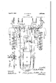
Figure 4 is a fragmentary side elevation showing the depth gauging means arranged forthe first ridging operation;
Figure 5 is a rear` view of the machine as arranged in Figure 4;
Figure 6 is a detail of the lifting connection to the axle of the gauge wheels; and
Figures 7 and 8 are enlarged detail views of the beam connecting means which serve to rigidly connect the beams of the furrow openers. l
n the particular embodiment illustrated, the reference numeral 1 indicates generally the tractor having the customary drive wheels 2 and drive housings 3. Pivotally connected to the front of the tractor, as by a bar or shaft 5, are a plurality of longitudinally extending beams 6. The beams 6 are connected to the shaft 5 by means of links or arms 9 and at their rear ends the beams 6 curve downwardly for connection with the furrow openers 11. i i
The usual planting mechanism is indicated by the reference numeral y15 and it is supported upon transversely extending bars 16 carried by brackets 18 which may be bolted to the drive housings 3.
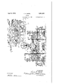
The longitudinally extending beams 6 are rigidly connected together at their rear ends by means of a transverse connecting melnber indicated in its entirety by the reference numeral 20. The member 20 comprises two I- beams 21 and 22 boltedtogether at their inner ends by two plate vmembers24 and 25, see Figures 7 and v8, and each of the plate members is made up of two plates as indicated in Figure -7. The outer plate. of each of the plate members 24 and v25 is adapted to fit .against the outer edges of the flanges of the I-beams while the inner plates of the plate members 24 and 25 are adapted to abut against *thev inner surfaces of the flanges of the I- beams 21 and 22. The plate members 24 and 25 areeach providedfwith four holes through which bolts 27 are adapted to be passed whereby the plate members 24 `-and 25 may be clamped or drawn up against the edges of the flanges ofthe I-beams 21 and 22. The adjacent ends of these flanges are apertured and'through theapertures bolts 29 are passed,
see Figure 8, whereby the iianges of the I- l beams 21 and 22 can'be drawn against the inner plates of the/plate members24 and 25, the Webs of the I-beams 21 and 22 being interrupted, as indicated by the reference numeral 30, for this purpose.
The outer ends of the I-beams 21 and 22 are each provided with a depending bracket 33 secured thereto, as by ,welding or the like. The brackets 33 are each bolted to the corresponding beam 6 by bolts 35 as indicated in Figures 1 and 4.
rllhe depth gauging mechanism is seen to` comprise a pair of gauge wheels 40 mounted v upon the inwardly turned horizontal portions of the crank axles.
Each of the crank.
these brackets rotatably receive the crankaxles 42 whereby the rear ends of thebeams 6 may be supported. Collars47 are provided for the purpose of preventing undesired transverse displacement of the crank axles 42 in the bearing'brackets 45, and these collars 47 maybe secured to the crank axles 42 by set screws projecting or threaded Kinto. holes formed in the crank axles 42. preferably supply a number .of holes therefor, such as are indicatedin Figure 5 by the reference numeral 50, for a scribed.
The manual means I have provided for advjusting the depth of operation of the furanism for retaining the levers 55 in any'- of` their adjusted positions. A link 56 is conpurpose later to be 'denected to the lever 55 at its forward end, f
and atits rearward end the levers 56 are each connect-ed to arms 57 bolted to an upwardly projecting lug 59 formed on or a part of a sleeve member 60. As is more clearly disclosed in Figure 6, the sleeve member 60 extends laterally in both directions from the lug 59 and is yadapted to embrace the crank axle 42. The sleeve member Has a pair of capv axles 42 tobe secured t0 thesleeve members' 60 in eitherof two positions.
One position `of the crank lgauge wheels 40 is shown in'full lines )in Fig-YV 12sV I axles 42 and the l;
11.*', 3. In this position it will be noted that the crank axles 42 are so adjusted as to bring the wheels 40 rearwardly of the furrow openers 11 and in their closest position,`that is, practically directly behind the drive wheels 2'so that they run on the ridges thrown up by the furrow openers 11, as indicated in Figure 2. 'VIhis is the position, it will be noted, for which the gauge wheels are 4adjustedwhen performing the second ridging operation.
When performing the first ridging operation the crank axles 42 and the gauging wheels 40 are positioned as shown in dotted .lines in Figure 3, that is, each of the crank axles are moved outwardly to space the gauge wheels 40 farther apart, the cap screws 63 being loosened to allow the crank axles to be moved relative to the sleeves 60 and the collars 47 being loosened to allow the crank axles to be moved outwardly relative to the bearing brackets 45 carried on the transverse connecting member 20. At the same time the crank axles 42 are cranked from a rearwardly extending position as shown in Figure 1 to a forwardly extending position as shown in in Figure 4, thus bringing the gauge wheels 40 from a position behind the drive wheels to a position laterally adjacent them.
During the first ridging operation it is preferable to detach the planting mechanism l5 and then subsequently attach the same for operation during the secondV ridging operation so that the planting is done at the latter time.
In order to prevent the ground working tools from swaying laterally with respect to the tractor I provide a pair of bumpers for attachment to the tractor at any convenient point. These bumpers 70 comprise a U- shaped bar the ends of which are bolted to the drive housings 3. The intermediate portions of the U-shaped bumpers 7 O extend in a vertical plane as indicated inFigure 2 and in a position to bear against the outer sides of the beams 6 to prevent them from swerving laterally. l.
When performing the first ridging operavtion the gauge wheels are positioned as shown in'Figure 5, and in this operation the rows or furrows are made consecutively across the field, that is, the implement is driven back and forth across the field, and when going in one direction the left hand gauge wheel 40 will run close to the adjacent furrow, see Figure 5, and in going in the other direction the right hand wheel will be the one running close to the adjacent furrow. During the second ridging and planting operation the opera! or plants two rows and then skips two rows, taking the next two, and so on. That is, the operator plants rowsrl and 2, 5 and 6, 9 and 10, and so on, and after he has covered the field in this manner, taking alternate pairs of rows, he starts back and opens up and plants in the rows he left, that is, rows 3 and 4, 7 and 8, and so on. When planting rows l and 2, etc., the drive wheels of the tractor run in the bottoms of the old furrows, as indicated in Figure 2, but in planting rows 3 and 4, etc., the drivewheels of the tractor are positioned to run on the adjacent half ridges previously formed.
lrVhen performing the second ridging and planting operation it is preferable to dispose the gauge wheels in the positions shown in Figures 2 and 3, rather than in the posi-- tions shown in Figures 4, and 5. In this second listing and planting operation if thel gauge` wheels are left in the position shown vtop of the covered seed. It is quite import--v ant that the seed be covered with just la right amount of soil and hence it is preferable inl this second listing and planting operation to dispose the gauge wheels in the lposition shown in Figure 2 where they will not cause soil to'roll down upon the covered seed. In this position, with each gauge wheel disposed substantially directly back of the rear tractor wheel, the gauge wheel will run on the top of the newly formed rid e, which is more or less flat, and where it is arthest removed from the seed rows in the furrows on either side thereof. As previously remarked, when the vgauge wheels are positioned as shown in Figure 5, in the first listing operation, the gauge wheel at one side of the implement will run close to the adjacent furrow when traveling in one direction, and when traveling in the other direction the gauge wheel on the opposite side of the implement will be the one running close to the adjacent furrow, the rows or vfurrows at this time being made consecutively across the field.
This relation of each gauge wheel relativev to the furrow, when the wheel is traveling adjacent to the furrow, is obtained by spacing each gauge wheel-laterally from thev adjacent tool or fuirrow opener a dist-ance equal v to the furrow spacing minus a little more than half the width of the furrow.
It will be apparent that the lateral spacing between the plow beams, 6, 6may be adjusted by loosening the bolts 27 and removing the bolts 29 (Figures 7 and- S) and sliding the beams 21 and 22 toward orfrom each-other, whereupon these beams can be rigidly securedtogether in their adjusted relation by replacing and retightening the bolts.
4I am well aware of the fact' that my invention may be employed in a different manner than that illustrated. For example, the
transverse connecting member. 20 together 80 1n Flgure 5, corresponding to their posltlon with thecrank axles 42 and gauge wheels 40 i might be separately employed for attach'- gether with 'the gauge wheels associated therewith, and substituting therefor the beam structure 20 and gauge wheels 40 as shown in' this application. Any suitable planting mechanism 15 may be employed, but as illustrative of one embodiment which may be used attention is directed to the' planting mechanism disclosed in the above mentioned application, which also discloses the details of the-yieldable hitch connection utilizing the vsprings connecting with the lower ends of the draft links or arms 9.
Another manner in which my invention .may be used is as follows. IVhere it is desired to plant'on the tops of the ridges, sweeps of the usual type are substitutedfo'r the furrow openers 11 which throw up a considerable ridge as indicated at the extreme right and left hand sides of Figure 2, and the gauge lwheels 40 are set to run n the bottom of the old fur-rows, the spacing of the wheels 40 being the same as shown in Figure 2 since the sweeps merely cut off the topportion of the ridge and thereis not enough soil displaced to fill up the old furrow as is the case when furrow openers 11 are used as shown in Figure 2.
While I havey described, in connection with the accompanying drawings, th specific form in which I prefer to' embody my invention, it
is to be understood that the invention is. not tobe limited to the speciiic means which I have herein shown and described, and that, in
. fact, widely different means may be vemployed in the practice'of the broader aspects of my invention.
' What I claim, therefore, and desire to secure by Letters Patent is l. In an implement of the class described, in combination, a tractor, a plurality of draft transmitting beams, means pivoting the beams tothe tractor, ground working tools carried by the beams, gauge wheels carried by the beams and adjustable in a plurality of fore and aft positions, and adapted to gaugex the operating depth of said tools.
2. In an implement of the class described, in combination, a tractor, a plurality of draft transmitting beams, means pivoting the beams to `the tractor, ground working tools `601 carried by the beams, gauge wheelscarried by the beams and adjustable in a plurality of lateral positions, and adapted to gauge the operating depth of said tools.
" 3. In an implement of the glass described in'combination, a tractor, a pluralityof draft transmittingA beams, means pivoting the the beams to and under the tractor in front v ofthe rear wheels thereof, ground working tools carried by the beams, gauge wheels carried by the beams and adjustable in a plurality of vertical and fore and aft positions,
and adapted to gauge theoperating depth of j said tools.
5. In an implement of the'class described in combination, a tractor, a plurality of beams, means pivoting the beams to the tractor, lground working tools carried by the beams, gauge wheels carried by the beams and. adjustablein a' plurality of vertical and lateral positions, and adapted to gauge the operating depth of saidtools.
6. InA an implement of the class described,
in combination, av tractor, a plurality of beams extending substantially longitudinally .0f the tractor, means pivoting lthe beams to the tractor, ground Working tools carried by the beams, gauge wheels carried by the beams and optionally movable to two separated fore l and aft positions and adapted to gauge vthe operating depth of said tools.v
7. In an implement of the class described, incombination, a tractor, a plurality of beams extending substantially longitudinally of the tractor, means pivoting vthe beams to the tractor, ground working tools carriedby the beams, gauge wheels carried bythe beams and optionally movable to two lateral positions and adapted to gauge the operating depth of said tools.
8. In an implementpf the class described, in combination, a tractor, c a plurality of beams extending substantially longitudinally of the tractor, means pivoting the beams to the tractor, ground working tools carried by the beams, gauge Wheels carried by the beams positions, and adapted to gauge the operating depth of said tooly 9. In an implement of the class described, in combination, a tractor having a rear axle, a plurality of beams in'a general fore and beams and adjustable in a plurality of ver- `and adjustable in a plurality of vertical posil tions and optionally rmovable to two lateral tical positions and optionally movable to two Y fore and. aft positions, and adapted to gauge the operating depth of said tools.
10.,The combination with a tractor in- `cluding front and rear wheels, of an implement comprising a plurality of lbeams extending substantially longitudinally of the tractor, means pivoting the beams to the tractor, ground working tools carried by the beams, gauge wheels carried by the beams and adjustable in a plurality of fore and aft positions, one position being directly behind the rear wheels and another being at one side of said rear wheels, said gauge wheels being adapted to control the operating depth of said tools.
11. The combination with a tractor including front and rear wheels, of an implement comprisingOa pluralityG of beams extending d substantially longitudinally of the tractor,
means pivoting the beams to the tractor, ground working tools carried by the beams, gauge wheels carried by the beams and adjustable in a plurality of lateral positions, one position being directly behind the rear wheels and another being at one side of saidj rear wheels, said gauge wheels being adapted to control the operating depth of said tools.
12. The combinationwith a tractor including front and rear wheels, of an implement comprising a plurality of draft transmitting beams, means pivoting vthe bea-ms to the tractor, ground working tools carried by the beams, gauge wheels carried by the beams and adapted to be spaced laterally from the tools a distance equal to the spacing between the tools less a distance equal to slightly more than half the width of the furrow opened by said tools.
13. The combination with atractor including front and rear wheels, of an implement comprising a plurality of beams extending substantially longitudinally of the tractor, means pivoting the beams to the tractor, furrow opening tools carried by the beams, gauge wheels carried by the beams and adapted to be spaced laterally therefrom such'a distance as to run on the ridges formed by said tools.
14. The combination with a tractor including front and rear wheels, of an implement lcomprising a plurality of beams extending substantially longitudinally of the tractor, means pivoting the beams to the tractor, furrow openin tools carried by the beams, gauge wheels carried by the beams and adapted to be spaced laterally from the tools such a distanize that they clear the ridges formed by said too s. l y w 15. An implemnt of the class described comprising, in combination, a tractor having frontv and rear wheels, a plurality of beams extending longitudinally of the tractor between and forwardly of the rear wheels thereof, means pivotally connecting the forward portions o the beams to the tractor, ground working tools carried by the beams at their rearward portions, means connecting the rear 1 portions of the beams together, crank axles beams to the tractor, -ground working tools carried by the beams at their rearward portions, meansconnecting therear portions'of the beams together, a pair of laterally extending crank axles, gauge wheels on the' cranks of the axles, and adjustable journaling means supporting the said beams and connecting means on the axles. v
17 An implement of the class described, comprising, in combination, a tractor having frontand rear wheels, a plurality of beams extending longitudinallylof the tractor and between the rear wheels thereof, means pivotallyvconnecting the forward portions of the beams to the tractor, ground working tools carried by-the beams at their rearward portions, means connecting the rear portions of the beams together, a pair of laterally extending crank axles, gauge wheels on the pranks of the axles, and adjustable journaling tending crank axles, gauge wheels on the cranks of the axles, and adjustable journaling means operable to swing the axles on thel beam connecting means at a number of selected lateral positions, one where the cranks of said axles extend rearwardly from the journaling means and another where the cranks extend forwardly. y
19. An implement of the class described comprising, in combination a tractor having front and rear wheels, a plurality of beams extendinglongitudinally of the' tractor and between the rear wheels thereof, means pivotally connecting the forward portions of the beams to the tractor, ground working tools carried by the beams at their rearward portions, means connecting the rear portions of the beams together, a pair of laterally extending cranks axles, gauge wheels on the cranks of the axles, means to rock said axles to raise and lower the beams relative to said wheels, said means comprising a ls leeve embracing each of the axles, cooperatmg means on the -sleeves and thevaxles whereby the las 105 tlie beams together, a pair of laterally exaxles maybe secured to the sleeves ina plurality ofselected positions and means to turn the sleeves, and means journaling the axles on said beam connecting means. j 20. An implement of the class described comprising, in combination, a tractor having front and rear wheels, a plurality of beams extending longitudinally of the tractor and between the rear wheels thereof, means pivotally connecting the forward portions ofy .the beams to the tractor, ground working tools carried by the beams at their rearward I portions, means connectingthe rear portions of the beams together, a'pair of laterally extending crank axles, gauge wheels onthe cranks ofthe axles, means to rock said axles to raise and lower the beams relative to said wheels, said means comprising a sleeve embracing each of the axles, cooperating means on the sleeves and the axles comprising set screw means on one part, and a number of sets of apertures on the other part lto receive the set screw means whereby the axles may be secured to the sleeves in a plurality of selected positions and means to turn the sleeves, means to prevent lateral displacel j ment of the axles when in their selected positions, and means journaling the axles on said `'beam connecting means.
comprising, in combination, a tractor having front and rear wheels, a plurality of beams extending longitudinally ofthe tractor and between the rear wheels thereof, means pivotally connecting the forward portions of the beams to the tractor, ground workingv tools carried by thebeams at their rearward portions, means connecting` the rear portions of f the beams together, a pair of laterally exv tending crank axles, gauge wheels onv the cranks of the axles, means to rock said axles to raise and lower the beams relative to said Wheels, said means comprising a sleeve embracing each Vof the axles, cooperating means on the sleevesand the axles comprising set screw means on one part and a number of sets of apertures on the other part to receive the set screw means whereby the axles may be secured to the sleeves in a plurality of selected positions and means to turn the sleeves, and means journaling the axles on said beam connecting means, said journaling means comprising apertured brackets secured to the beam connecting means, the axles being supported in the apertures of the brackets. 22. An implement of the class described comprising, in combination, a tractor having front and rear'wheels, a plurality of beams extending longtudinally of the 'tractor and between the rear wheels thereof, means pivotally connecting the forward portionsof the beams to the tract'or, ground working tools carried by the beams at their rearward portions, means connecting the rear portions 5 of the beams together, a pair of laterally ex- 21. An implement of the class described `movement thereof.
tending crank axles, gauge wheels on the cranks of the axles, means to rock said axles oto raise and lower the beams relative to said wheels, said means comprising a sleeve emf bracing each of the axles, cooperating means on the sleeves and the axles comprising set screw means on one part and a number of sets of apertures on the other part to receive the set screw means whereby the axles ni'ay be secured to the sleeves in a plurality of selectedpositions and means to turn the sleeves, and means journaling the axles on said beam connecting means, said journaling means comprising apertured brackets secured to the beam connecting means, the axles being supported in the apertures of the brackets and .the rear ends of the beams together, earth working tools carried on the beam, and bumpers carried onthe tractor in a position to be contracted by the beams to limit lateral movement thereof.
24. An agricultural machine of the class described comprising, in combination, a tractor, a plurality of beams extending longitudinally of the tractor, means pivotally connecting the front'ends of the beams with the tractor, means connecting the rear ends of the beams together, earth workingtools carried on the beam, and bumpers secured to the drive housings of the tractor and in a position to be contacted by the beams to limit lateral 25. An agricultural machine of the Vclass described comprising, in combination, a tractor, a plurality of beams extending in a generally fore and aft direction relative to the tractor, means pivotally connecting the front ends of the beams with the tractor, means connecting the rear ends of the beams tor gether, earth working tools carried on the beam, and bumpers comprising U-shaped brackets having the vends thereof secured toy the drive housings of the tractorl and their intermediate portions extending in a vertical plane longitudinally of the tractor and in a position to be contracted by the beams to limit lateral movement thereof. v
26. In an implement of the class described, the combination witha tractor havin longi' tudinally extending beams connecte there'- with, of a transversely extending member adapted to `be secured to the beams and provided with crank axles, gauge wheels on the cranks, and means to connect the axles to the member in a number Lof selected positions whereby the spacing between the gauge wheels is' adj usted.
27. In an implement of the class described, the combination with a tractor havinga plurality of draft transmitting beams connected therewith, of a transversely extending member adapted to be rigidly secured to the beams and provided with crank axles, gauge wheels on the cranks, and means to connect the axles to the member in a number of selected positions where the gauge wheels may be adjusted at will tovrun on different portions of the ground relative to that traversed by the tractor.
28. In an implement of the class described, the combination with a tractor having longitudinally extending beams connected therewith provided with furrow opening tools, of a transverse connecting member and adapted to be secured to the beams and pro-l vided with crank axles, gauge wheels on the cranks, and means to connect the axles to the member in a number of selected positions whereby the axles can be adjusted at will so that the gauge wheels will run on the land or on the ridges formed by the tools.
29. A device of the class described comprising beam connecting means including a two part member, means for adjustably securing said parts together, attaching brackets at the ends of said member, crank axles journaled to said member, each of said axles including a crank and parallel extending axles,
one journaled to said member, gauge wheels attaching means carried by the member,l
crank axles having gauge wheels, and means on the other, means including collars for maintaining the crank axles in a plurality of selected positions whereby the spacing between the gauge wheels maybe adjusted to suit' operating conditions, and means including a sleeve having a lug whereby eachv of the crank axles may be rocked.
30. A device of the class described comprising a beam connecting member including a pair of I-beams and means cooperating with the flanges of said I-beamsto maintain them in adjusted end to end relation, beam attaching means carried by the member, crank axles having gauge wheels, and means rotatably connecting the axles and said member and comprising means adapted to be secured to the axles at a number of selected positions thereon.
31. A device of the' class described comprising a beam connecting member including a pair of I-beams and means cooperating taching means carried by the member, crank axles having gauge wheels, and means rotatably connecting the axles and said member, said'means being so arranged that said axles and members arel connected for relative movement in a number of spaced relative ing the axles and said member, said meansV being so arranged that said axles and members are connected for relative movement in a number-of spaced relative positions.
34. A device of the class described comprising a beam connecting member includv ing a pair of structural sections, each having a iang, a pair of plates having means to f engage the edges and one surface `of the flange on each section, means to draw the flanges against the plates, and means to draw the plates against the flanges whereby the said sections are maintained in adjusted relation, beam attaching means carried by the vmember,'crank axles having gauge wheels,
and means rotatably connecting the axles and said member, said means being so arranged thatls'aid axles and members are connected for relative movement in a number of spaced relative positions.
In witness whereof, I hereunto subscribe' my name this 17 day of April, 1930. 1
V CHARLES H. WHITE.
with the flanges of said I-beams to maintain them in adjusted-end to end relation, beam rotatably connecting the axles and said mem- -ber whereby the gauge wheels are movable in l selected transversely spaced planes.
82. A device of the class described comprising a beam connecting member including a pair of I-beams and means cooperating with the flanges of said I-beams to maintain them in adjusted end .to end relation, beam at- CERTIFICATI; or. CORRECTION.
Patent-N0. 1;.ss1,f99` 3 Y' Granted Apri15,193z, to
'e CHARLES H. WHITE. l
It is hereby certified that error appears in the'printed specification of the above nunbered-patentrequiring correction'as followsfg Page 4, linev 121, claim v 59, f or the word 1"generalf' Vread generally; page 6, line 87, claim y23, after the wordl "Beams" 'insert a comma, line 88,v for "end" read ends, and line. 93, for "contracted" read contacted"; same page, line 119, claim 25, for -"contracted" read contacted; and thatthe said Letters Patent should be read with thesecor- 4 l 1 re'ctions' therein that 'the same mayconform to the` record of the case 'in the Patent Office. l Signed -andseaied this 14th day of June, yA. D. 1932.
M. J. Moore,
l (SeaU-j'lw i X ctingcommissionercf Patents.
Priority Applications (1)
| Application Number | Priority Date | Filing Date | Title |
|---|---|---|---|
| US446813A US1851993A (en) | 1930-04-24 | 1930-04-24 | Lister |
Applications Claiming Priority (1)
| Application Number | Priority Date | Filing Date | Title |
|---|---|---|---|
| US446813A US1851993A (en) | 1930-04-24 | 1930-04-24 | Lister |
Publications (1)
| Publication Number | Publication Date |
|---|---|
| US1851993A true US1851993A (en) | 1932-04-05 |
Family
ID=23773928
Family Applications (1)
| Application Number | Title | Priority Date | Filing Date |
|---|---|---|---|
| US446813A Expired - Lifetime US1851993A (en) | 1930-04-24 | 1930-04-24 | Lister |
Country Status (1)
| Country | Link |
|---|---|
| US (1) | US1851993A (en) |
-
1930
- 1930-04-24 US US446813A patent/US1851993A/en not_active Expired - Lifetime
Similar Documents
| Publication | Publication Date | Title |
|---|---|---|
| US3110275A (en) | Combined planting machine | |
| US3367293A (en) | Landscaping implement | |
| US3528507A (en) | Field tillage apparatus | |
| US2426529A (en) | Reversible mountable gauge wheel unit | |
| US2337662A (en) | Agricultural implement | |
| US2793576A (en) | Fluid operated cultivator | |
| US1851993A (en) | Lister | |
| US2221769A (en) | Tractor attachment | |
| US3055322A (en) | Planter frame | |
| US1493448A (en) | Agricultural implement | |
| US1846459A (en) | Combination agricultural implement | |
| US2371839A (en) | Tractor-mounted implement | |
| US2259864A (en) | Implement attachment for tractors | |
| US2347017A (en) | Rotary soil tiller | |
| CN209609135U (en) | It is a kind of parallel connection modified greenhouse corps plantation use scarifier attachment | |
| US2586254A (en) | Sugar cane stubble digger | |
| US2626548A (en) | Rigid implement frame for fourwheeled tractors | |
| US1918730A (en) | Plow | |
| US757443A (en) | Plow. | |
| US2071118A (en) | Cultivator attachment for tractors | |
| US2052114A (en) | Tractor stalk cutter and plow | |
| US3037469A (en) | Minimum tillage planter | |
| US2833231A (en) | Grain drill with laterally swinging furrow opener | |
| US1054659A (en) | Ground-working machine. | |
| US11083123B2 (en) | Multi-purpose agricultural implement |