US1851989A - Electrical generating system - Google Patents
Electrical generating system Download PDFInfo
- Publication number
- US1851989A US1851989A US404725A US40472529A US1851989A US 1851989 A US1851989 A US 1851989A US 404725 A US404725 A US 404725A US 40472529 A US40472529 A US 40472529A US 1851989 A US1851989 A US 1851989A
- Authority
- US
- United States
- Prior art keywords
- switch
- load
- mains
- winding
- relay
- Prior art date
- Legal status (The legal status is an assumption and is not a legal conclusion. Google has not performed a legal analysis and makes no representation as to the accuracy of the status listed.)
- Expired - Lifetime
Links
Images
Classifications
-
- H—ELECTRICITY
- H02—GENERATION; CONVERSION OR DISTRIBUTION OF ELECTRIC POWER
- H02J—ELECTRIC POWER NETWORKS; CIRCUIT ARRANGEMENTS OR SYSTEMS FOR SUPPLYING OR DISTRIBUTING ELECTRIC POWER; SYSTEMS FOR STORING ELECTRIC ENERGY
- H02J3/00—Circuit arrangements for AC mains or AC distribution networks
- H02J3/38—Arrangements for feeding a single network from two or more generators or sources in parallel; Arrangements for feeding already energised networks from additional generators or sources in parallel
Definitions
- This invention relates to electrical generating systems.
- the invention relates more particularly to generating systems in which a plurality of gas engine driven units are employed for supplying current to a single load circuit.
- 1,796,810 there is disclosed an automatic generating system employing two generating units of different capacities.
- the smaller generator unit is automatically controlled to supply current to the load circuit under light load conditions while the larger genera-tor unit is automatically controlled to supply current to the load circuit when the current demand exceeds the capacity of the smaller generator unit.
- the small generator unit is operative only under light load conditions and the maximum capacity of the generating system is determined by the generating capacity of the large generating un1t.
- the present invention has among its objects to provide an automatic controller for systems of the aforesaid character which provides for operation of each of the generator units alone under certain load conditions and 35 for parallel operation thereof under other load conditions.
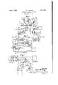
- FIG 1 schematically illustrates an automatic control system embodying the invention
- Fig. 2 diagrammatically illustrates a preferred form of starter which is employed in Serial No. 404,725.
- a small generator unit 1 and a large generator unit 2 each of which includes a generator G and an internal combustion engine E for driving the same.
- Each of said units go is provided with a starter S and as hereinafter set forth a controller C cooperates with the starters S to control said units in the following manner.
- the small generator unit 1 is rendered operative to supply current to the service mains L L under light load conditions and when the current demand exceeds the capacity of the small generator unit 1 but is within the capacity of the large generating unit 2 the latter unit is rendered 2" operative to supply current to said mains and the smaller generator unit is stopped.
- the generator units are operated in parallel to sup- 7 5 ply current to said mains.
- the startersS of units 1 and 2 are of the same type, and in Fig. 2 one of the starters is illustrated in connection with the small generator unit 1.
- Said starter includes a starting switch 5 and a-main switch 6.
- Starting switch 5 provides for connection of the generator to a storage battery B for operation thereof as a motor for cranking of the engine, and as hereinafter set forth said starting switch is controlled through the medium of a normally open relay 7 a normally closed governor operated switch 8 and normally closed auxiliary contacts 6 associated with main switch 6.
- starting switch 5 extending from the negative side of battery B thro'ugh'relay 7 through auxiliary contacts 6 associated with'maln switch 6 through the winding 5 of starting switch 5 and through the governor operated switch 8 to the positive side of battery B.
- Starting switch 5 in responding establishes a circuit extending from the left hand terminal of armature A through battery 13' through switch 5 and through the series field F to the right hand terminal of said armature.
- the generator G thenoperates as amotor to crank the engine E.
- the controller G shown in Fig. 1 includes electro-responsive transfer switches 10 and 11 and an equalizing switch 12.
- Switch 10 is normally closed and provides for connection of service main L to main Z of the small generator unit 1 while switch 11 is normally open and is responsive to connect service main L to main. Z of the large generator unit 2.
- Switch 12 is normally open and is adapted as hereinafter set forth to establish an equalizing connection between the generators of the two units during parallel operation thereof.
- ControllerC also'includes relays 13 14 15 and 16 and a knife switch 17.
- switch 10 is provided with normally open auxiliary 11 and normally closed auxiliary contacts:
- switch 12 is provided with normally closed auxiliary contacts 12 which are arranged to open only upon'closure of said switch.
- relay 13 is provided with normally closed contacts 13 and normally open contacts 13 and the same is provided with a series operating winding 13 and a shunt holding winding 13.
- Relays '14 and 16 are normally open and relay 15 is normally closed and each of said relays has a winding a associated therewith for effecting response thereof.
- controller closed to connect a load across service mains L L the small generator unit 1 will be automatically started as described in connection with Fig. 2 to supply current tothe load.
- the small generator ,unit remains in operation as long as the load across the service mains L L does not exceed the capacity of said unit.
- relay 13 When the load connected across service mains L --L exceeds the capacity of the small generator unit 1 relay 13 responds under the action of its operating inding 13. Upon response of relay 13 the contacts 13 thereof close and the winding 13 of said relay 13 is then connected across the mains Z Z of the large generating unit 2 through the medium of auxiliary contacts 11 of transfer switch 11. Also upon response of relay 13 relay winding 11 is connected across mains Z Z of the large generator unit through the medium of contacts 13 and relay 15 while relay winding 10 is connected'across said mains through the medium of contacts 13 relay 15 and auxiliary contacts 12' associated with equalizing switch 12.
- Relay windings 10 and 11 are of relatively high resistance and relay winding 13 is of relatively low resistance and the latter winding acts as a load across the mains of the large generator unit 2 to effect starting of said unit, as described in connection with ig.
- the windings 10 and 11 effect response of their respective switches.
- Transfer switch 10 in responding disconnects the small 'enerator unit 1 from the service mains L*L and transfer switch 11 in responding connects the larger unit to said mains.
- switch 12 in closing establishes a connection between the right hand terminal of armature A of unit 1 and the left hand terminal of armature A of unit '2.
- such connection provides for equalization of the terminal voltage of the two generators 1 and 2.
- the auxiliary contacts 12 thereof open to interrupt the aforedescribed energizing circuit for the coil 10 of transfer switch 10.
- Transfer switch 10 then returns to normal position to connect the generator of the small unit 1 in parallel with the generator of the large unit 2.
- the load across the service mains L L is then supplied by both generators.
- the auxiliary contacts 10 disconnect resistance r from the mains Z Z of the small generator unit 1.
- winding 13 permits relay 13 to return to normal position and the operating windings 10 and 11 of the transfer switches are then maintained energized through the auxiliary contacts 11 of the latter transfer switch. Also upon return of relay 13 to normal position the contacts 13 thereof connect the winding 16* of relay 16 across mains Z Z of the large generator unit 2 through the medium of the auxiliary contacts 11 of transfer switch 11. Relay 16 then responds to connect a resistance and the coil 15 of relay 15 across the mains Z -Z of the small generator unit 1. Resistance r and coil 15 act as a load across the mains and the small generator unit 1 to eifect starting thereof in the manner hereinbefore set forth.
- two generating units of difierent rent to said load circuit under different predetermined load conditions and to render both of said units operative to supplycurrent to said load circuitunder other predetermined load conditions.
- a common load circuit'therefor means responsive to load conditions in said circuit for selectively rendering one or theother of said generating units operative upon diflerent predetermined load conditions in sand circuit, means assoclated with said former means to efiect parallel operation of said units under other predetermlned load conditlons msaid circuit and.
Landscapes
- Engineering & Computer Science (AREA)
- Power Engineering (AREA)
- Control Of Eletrric Generators (AREA)
Description
April 5, 1932. E. w. SEEGER 1,851,989
ELECTRICAL GENERATING SYSTEM Filed Nov. 4, 1929 @A 13 12' Asa/{P 5 F Ezra- =8- a 5 WT UNIT N0. ,2
UNIT NO. 3
(WIT NQ- 1 6m x BMW "1. $mgw Patented Apr. 5, 1932 a i r a 'TATS EDVVIN W. SEEGEB, 01? WAUWATOSA, WISCONSIN, ASSIGNOR TO CUTLER-HAMMER, II\TC., CF MILWAUKEE, WISCONSIN, A CORPORATION OF DELAWARE ELECTRICAL GENERATING SYSTEM Application filed November 4, 1929.
This invention relates to electrical generating systems.
7 The invention relates more particularly to generating systems in which a plurality of gas engine driven units are employed for supplying current to a single load circuit.
In the copending application of Edwin X. Schmidt and Walter O. Baer, erial No. 404,488 filed Nov. 11, 1929, now Patent No.
1,796,810, there is disclosed an automatic generating system employing two generating units of different capacities. The smaller generator unit is automatically controlled to supply current to the load circuit under light load conditions while the larger genera-tor unit is automatically controlled to supply current to the load circuit when the current demand exceeds the capacity of the smaller generator unit. In this system the small generator unit is operative only under light load conditions and the maximum capacity of the generating system is determined by the generating capacity of the large generating un1t.
In some systems the small generating unit has considerable generating capacity and by providing for parallel operation of the generator units the capacity of the system can be materially increased.
The present invention has among its objects to provide an automatic controller for systems of the aforesaid character which provides for operation of each of the generator units alone under certain load conditions and 35 for parallel operation thereof under other load conditions.
Various other objects and advantages of the invention will hereinafter appear.
The accompanying drawings illustrate a generating system embodying tne invention which will now be described, it being understood that the system illustrated is susceptible of modification without departing from the spirit and scope of the appended claims.
In the drawings:
Figure 1 schematically illustrates an automatic control system embodying the invention;
Fig. 2 diagrammatically illustrates a preferred form of starter which is employed in Serial No. 404,725.
connection with each of the gas engine driven units shown in Fig. 1, and
Fig. 3 is an across-the-line diagram illustrating the circuit connections of certain of the control elements shown in Fig. 1.
Referring to Fig. l, the same illustrates a small generator unit 1 and a large generator unit 2, each of which includes a generator G and an internal combustion engine E for driving the same. Each of said units go is provided with a starter S and as hereinafter set forth a controller C cooperates with the starters S to control said units in the following manner. The small generator unit 1 is rendered operative to supply current to the service mains L L under light load conditions and when the current demand exceeds the capacity of the small generator unit 1 but is within the capacity of the large generating unit 2 the latter unit is rendered 2" operative to supply current to said mains and the smaller generator unit is stopped. When the current demand exceeds the capacity of the large generator unit the generator units are operated in parallel to sup- 7 5 ply current to said mains.
Generators G of units 1and2are ofthe same type, and as shown in Fig. 2 each is provided with an armature A, series field windings F and F and a shunt field winding F The startersS of units 1 and 2 are of the same type, and in Fig. 2 one of the starters is illustrated in connection with the small generator unit 1. Said starter includes a starting switch 5 and a-main switch 6. Starting switch 5 provides for connection of the generator to a storage battery B for operation thereof as a motor for cranking of the engine, and as hereinafter set forth said starting switch is controlled through the medium of a normally open relay 7 a normally closed governor operated switch 8 and normally closed auxiliary contacts 6 associated with main switch 6. Relay 7 is provided with normally closed auxiliary contacts 7 a for controlling a magneto ground circuit 9 for the engine, and said relay is provided with a shunt winding 7 and a series winding 7. Main switch 6 provides for connection of generator G to mains Z and Z and the same is provided with a shunt winding 6 and a series winding 6. Main switch 6 is also provided with normally open auxiliary contacts 6 for establishing a matic start is made by connecting aload across the mains Z Z. Upon connection of a load across said mains circuit is established from the negative side of battery B through the series winding 7 of relay 7 to main Z thence through the load to main Z through the shunt winding 7 b of relay 7 and through resistance r to the positive side of battery B. Winding 7 efiects response of relay 7 and said relay in responding removes the ground connection GR from the magneto of the engine and establishes an energizing circuit for.
starting switch 5 extending from the negative side of battery B thro'ugh'relay 7 through auxiliary contacts 6 associated with'maln switch 6 through the winding 5 of starting switch 5 and through the governor operated switch 8 to the positive side of battery B. Starting switch 5 in responding establishes a circuit extending from the left hand terminal of armature A through battery 13' through switch 5 and through the series field F to the right hand terminal of said armature. The generator G thenoperates as amotor to crank the engine E.
It will be observed from Fig. 2 that the winding 6 of main switch 6 is connected across the armature A and seriesfield winding F and when the engine functions to drive the generator, current issupplied to said winding to effect response of main switch 6. Main switch 6 in responding interrupts the aforedescribed energizing circuit for starting switch 5 extending through auxiliary contacts 6 and establishes circuit from the right hand terminal of the armature A through series field winding F 2 through winding 6 to main Z whereby the load connected across mains Z Z is supplied with current by generator G. Also upon response of main switch 6 the auxiliary contacts 6 thereof establish a charging circuit for battery B through the medium of resistance 7. Winding 6 holds main switch 6 in closed position as long as a load is connected across main Z Z and upon removal of such load said winding is deenergiz'ed to permit opening of main switch 6.
As aforestated starting switch 5 is energized through the medium of the governor operated switchv 8. When the generator operates at a speed in excess of its cranking speed switch 8 opens to interrupt the energizing circuit for starting switch 5. Thus should the load be removed from mains Z -Z and reconnected thereto before the engine speed is reduced below cranking speed, the open governor switch 8 prevents closing of the motor starting circuit unnecessarily and so avoids a direct connection between the battery and the generator terminals while the generator is developing its higher voltage.
From the foregoing it will be observed that the starter illustrated in Fig. 2 provides for automatic starting of the generator unit upon connection of a load across the supply mains and for automatic stopping thereof upon removal of the load. V
The controller G shown in Fig. 1 includes electro- responsive transfer switches 10 and 11 and an equalizing switch 12. Switch 10 is normally closed and provides for connection of service main L to main Z of the small generator unit 1 while switch 11 is normally open and is responsive to connect service main L to main. Z of the large generator unit 2. Switch 12 is normally open and is adapted as hereinafter set forth to establish an equalizing connection between the generators of the two units during parallel operation thereof. ControllerC also'includes relays 13 14 15 and 16 and a knife switch 17.
For purposes hereinafter set forth switch 10 is provided with normally open auxiliary 11 and normally closed auxiliary contacts:
11. Contacts 11 are arranged to open only upon closure of switch 11. Also for purposes hereinafter set forth switch 12 is provided with normally closed auxiliary contacts 12 which are arranged to open only upon'closure of said switch.
Also as shown in Fig. 1 relay 13 is provided with normally closed contacts 13 and normally open contacts 13 and the same is provided with a series operating winding 13 and a shunt holding winding 13. Relays '14 and 16 are normally open and relay 15 is normally closed and each of said relays has a winding a associated therewith for effecting response thereof.
The function and operation of controller closed to connect a load across service mains L L the small generator unit 1 will be automatically started as described in connection with Fig. 2 to supply current tothe load. The small generator ,unit remains in operation as long as the load across the service mains L L does not exceed the capacity of said unit.
When the load connected across service mains L --L exceeds the capacity of the small generator unit 1 relay 13 responds under the action of its operating inding 13. Upon response of relay 13 the contacts 13 thereof close and the winding 13 of said relay 13 is then connected across the mains Z Z of the large generating unit 2 through the medium of auxiliary contacts 11 of transfer switch 11. Also upon response of relay 13 relay winding 11 is connected across mains Z Z of the large generator unit through the medium of contacts 13 and relay 15 while relay winding 10 is connected'across said mains through the medium of contacts 13 relay 15 and auxiliary contacts 12' associated with equalizing switch 12. Relay windings 10 and 11 are of relatively high resistance and relay winding 13 is of relatively low resistance and the latter winding acts as a load across the mains of the large generator unit 2 to effect starting of said unit, as described in connection with ig. When the voltage across the mains Z -Z of the large generator unit 2 reaches a predetermined value the windings 10 and 11 effect response of their respective switches. Transfer switch 10 in responding disconnects the small 'enerator unit 1 from the service mains L*L and transfer switch 11 in responding connects the larger unit to said mains. Upon disconnection of the small generator unit 1 from the service mains L the same stops as set forth in connection with Fig. 2 and the load across the service mains L L is now supplied with current by the large generator unit 2.
In connection with the foregoing it should be noted that upon opening of switch 10 the winding 13 of relay 13 is deenergized. However, during closure of switch 11 relay 13 is held in its operated position by its winding 13 which is energized as hereinbefor described. Following closure of transfer switch 11 the auxiliary contacts 11 thereof open to deenergize the winding 13 but in the meantime the winding 13 of relay 13 is energized by current supplied to the load through switch 11 and said relay is thus held in its operated position.
Assuming now that the load across the service mains L -L exceeds the capacity of the large generator unit 2, the winding 1% then effects response of relay 1 1-. Relay l l in closing connects the operating winding 12 of equalizing switch 12 across the mains Z Z of the small generator unit and also connects a resistance 7' across said mains through the medium of auxiliary contacts 10 of transfer switch 10. Resistance 9' and relay coil 12 then act as a load on the small generator unit to effect starting thereof as set forth in connection with Fig. 2. When the voltage of the small generator unit 1 reaches a given value winding 12 efiects response of equalizing switch 12 and as shown in Fig. 2 switch 12 in closing establishes a connection between the right hand terminal of armature A of unit 1 and the left hand terminal of armature A of unit '2. As is well known, such connection provides for equalization of the terminal voltage of the two generators 1 and 2. Following closure of switch 12 the auxiliary contacts 12 thereof open to interrupt the aforedescribed energizing circuit for the coil 10 of transfer switch 10. Transfer switch 10 then returns to normal position to connect the generator of the small unit 1 in parallel with the generator of the large unit 2. The load across the service mains L L is then supplied by both generators. Upon return of switch 10 to normal posit-ion the auxiliary contacts 10 thereof disconnect resistance r from the mains Z Z of the small generator unit 1.
Assume now that the load across the service mains L L decreases to a value which is within the capacity of the large generator unit 2. Winding 14* then permits relay 1% to re turn to normal position. This results in deenergization of equalizing switch 12 and said switch in returning to normal position interrupts the aforedescribed equalizing connection between the generators of the units and the auxiliary contacts 12 thereof again establish the aforedescribed energizing circuit for the coil 10 of transfer switch 10. Transfer switch 10 then responds to disconnect the small generator unit 1 from the service mains L L and said unit is stopped as described in connection with Fig. 2.
Upon afurther decrease in load to a value within the capacity of the small generator unit 1 winding 13 permits relay 13 to return to normal position and the operating windings 10 and 11 of the transfer switches are then maintained energized through the auxiliary contacts 11 of the latter transfer switch. Also upon return of relay 13 to normal position the contacts 13 thereof connect the winding 16* of relay 16 across mains Z Z of the large generator unit 2 through the medium of the auxiliary contacts 11 of transfer switch 11. Relay 16 then responds to connect a resistance and the coil 15 of relay 15 across the mains Z -Z of the small generator unit 1. Resistance r and coil 15 act as a load across the mains and the small generator unit 1 to eifect starting thereof in the manner hereinbefore set forth. hen the voltage of the small generator unit 1 reaches a given value winding 15 effects response of relay 15 to interrupt the aforedescribed energizing circuit for coils 10 and 11 of the transfer switches 10 and 11. Transfer switch 11 thus opens to disconnect the service mains L L from the mains Z Z of the large generator unit 2 and switch 10 in returning to normal position connects said service mains to the mains Z Z of the small generator unit sistance r from the mains of the small generator unit 1. Under no load conditions the small generator unit 1 is stopped as hereinbefore set forth.
When knife switch 17 ismoved into lts left hand pos1t1on-the small generator unit 1 is rendered inoperative since the service main L is then connected to main Z of the large generator unit 2. However, as is apparent from the descriptionin connection with Fig. 2 the large generator unit 2 is then operative to supply current to' the service mains L1 IJ2 upon connection of a load across the same.
What I claim-as new and desire to secure by Letters Patent is:
1. In a system of electrical distribution, in combination, two generati. g units of difierent capacities, a sin le load circuit to be supplied thereby and means responsive to load conditions in said circuit ;or controlling said units to selectivelyrencer one or theother'of the same operative to supply current to said load circuit under different predetermined load conditions, and to render both of said units operative to supply current to said load circuit'under other predetermined load condi-' tions.
2. In a system of electrical distribution, in
combination, two generating units of difierent rent to said load circuit under different predetermined load conditions and to render both of said units operative to supplycurrent to said load circuitunder other predetermined load conditions.
3. In a system of electrical distribution, in
combination, two gas-engine-operated generating units of different capacities, a common load circuit therefor normally connected to the smaller of said units, means for starting each of said units upon current demand across the mains thereof, and means associated with said former means to render'the larger of said units operative alone to supply current to said load circuit under given load conditions, and to render both of said units operative to supply current to said load circuit under otherload conditions.
' 4. In a system of electrical distribution, in combination, two gas-engine-operatedgenerating units of different capacities, a common load circuit'therefor, means responsive to load conditions in said circuit for selectively rendering one or theother of said generating units operative upon diflerent predetermined load conditions in sand circuit, means assoclated with said former means to efiect parallel operation of said units under other predetermlned load conditlons msaid circuit and.
means for equalizing the terminal voltage of" said units upon operation thereof. in parallel.
5. In a system of electrical distribution, in combination, two gas-engine-operated generating units of different capacities, a common load circuit to be supplied thereby, an automatic controller associated with each of said units to effect starting thereof upon current demand across the mainsthereof, means associated with said controllers to render the smaller of said units operative to supply current to said load circuit when the current demand is within the capacity of the smaller of of said larger unit, and means associated with said controllers for rendering both of said units operative to supply current to said load circuit when the current demand exceeds the capacity of the larger of said units.
In witness whereof, I have hereunto subscribed my name.
EDl/VIN W. SEEGER.
CERTIFICATE OF CORRECTION.
Patent No. 1,851,989. April 5, 1932.
EDWIN W, SEEGERt It is hereby certified that error appears in the printed specification of the above numbered patent requiring correction as follows: Page 4, lines 67 and 68, claim 4, strike out the words "means associated with said former means" and insert the word and; and that the said Letters Patent should be read with this correction therein that the same may conform to the record of the case in the Patent Office.
Signed and sealed this 12th day of July, A. D. 1932.
M. J. Moore, (Seal) Acting Commissioner of Patents.
CERTIFICATE OF CORRECTION.
Patent No. 1,851,989. April 5, 1932.
EDWIN W, SEEGER It is hereby certified that error appears in the printed specification of the above numbered patent requiring correction as follows: Page 4, lines 67 and 68, claim 4, strike out the words "means associated with said former means" and insert the word and; and that the said Letters Patent should be read with this correction therein that the same may conform to the record of the case in the Patent Office.
Signed and sealed this 12th day of July, A. D. 1932.
M. J. Moore,
(Seal) Acting Commissioner of Patents.
Priority Applications (1)
| Application Number | Priority Date | Filing Date | Title |
|---|---|---|---|
| US404725A US1851989A (en) | 1929-11-04 | 1929-11-04 | Electrical generating system |
Applications Claiming Priority (1)
| Application Number | Priority Date | Filing Date | Title |
|---|---|---|---|
| US404725A US1851989A (en) | 1929-11-04 | 1929-11-04 | Electrical generating system |
Publications (1)
| Publication Number | Publication Date |
|---|---|
| US1851989A true US1851989A (en) | 1932-04-05 |
Family
ID=23600777
Family Applications (1)
| Application Number | Title | Priority Date | Filing Date |
|---|---|---|---|
| US404725A Expired - Lifetime US1851989A (en) | 1929-11-04 | 1929-11-04 | Electrical generating system |
Country Status (1)
| Country | Link |
|---|---|
| US (1) | US1851989A (en) |
Cited By (3)
| Publication number | Priority date | Publication date | Assignee | Title |
|---|---|---|---|---|
| US2611877A (en) * | 1951-10-12 | 1952-09-23 | Allen Bradley Co | Automatic starting electrical control circuit for engine driven electric power generators |
| US2655603A (en) * | 1952-08-14 | 1953-10-13 | Bell Telephone Labor Inc | Power supply apparatus for alternately supplying a load |
| US2666872A (en) * | 1950-08-19 | 1954-01-19 | Westinghouse Electric Corp | Electric power system for aircraft |
-
1929
- 1929-11-04 US US404725A patent/US1851989A/en not_active Expired - Lifetime
Cited By (3)
| Publication number | Priority date | Publication date | Assignee | Title |
|---|---|---|---|---|
| US2666872A (en) * | 1950-08-19 | 1954-01-19 | Westinghouse Electric Corp | Electric power system for aircraft |
| US2611877A (en) * | 1951-10-12 | 1952-09-23 | Allen Bradley Co | Automatic starting electrical control circuit for engine driven electric power generators |
| US2655603A (en) * | 1952-08-14 | 1953-10-13 | Bell Telephone Labor Inc | Power supply apparatus for alternately supplying a load |
Similar Documents
| Publication | Publication Date | Title |
|---|---|---|
| US3378755A (en) | Alternator power supply system | |
| US2085072A (en) | Small electric power plant | |
| US1851989A (en) | Electrical generating system | |
| US2213892A (en) | System of motor control | |
| US2595749A (en) | Electric motor-driven installation | |
| US2154314A (en) | Motor control | |
| US2179680A (en) | Controller for electric generating systems | |
| US1796810A (en) | Electrical generating system | |
| US2314588A (en) | Generating electric drive and control system | |
| US1411700A (en) | Motor controller | |
| US1706119A (en) | Power system | |
| US2314587A (en) | Generating electric drive and control system | |
| US2282874A (en) | Power system including rotary transformers | |
| US2666872A (en) | Electric power system for aircraft | |
| US2278632A (en) | Generator control system | |
| US1515166A (en) | Electrical system | |
| US1737722A (en) | Electrical system | |
| US2130584A (en) | Welder | |
| US2197888A (en) | Welder | |
| US1873168A (en) | Electrical apparatus | |
| US2679012A (en) | Starting system for thermal prime movers | |
| US2141624A (en) | Charging storage batteries | |
| US1475746A (en) | Automatic lighting system | |
| US1896093A (en) | Control system | |
| US2075666A (en) | Control system |