US1851985A - Cutter - Google Patents
Cutter Download PDFInfo
- Publication number
- US1851985A US1851985A US364218A US36421829A US1851985A US 1851985 A US1851985 A US 1851985A US 364218 A US364218 A US 364218A US 36421829 A US36421829 A US 36421829A US 1851985 A US1851985 A US 1851985A
- Authority
- US
- United States
- Prior art keywords
- blades
- jaw
- handles
- armor
- cutter
- Prior art date
- Legal status (The legal status is an assumption and is not a legal conclusion. Google has not performed a legal analysis and makes no representation as to the accuracy of the status listed.)
- Expired - Lifetime
Links
- 238000005520 cutting process Methods 0.000 description 32
- 239000004020 conductor Substances 0.000 description 4
- 230000000694 effects Effects 0.000 description 4
- 238000010008 shearing Methods 0.000 description 3
- 230000000295 complement effect Effects 0.000 description 2
- 230000037431 insertion Effects 0.000 description 2
- 238000003780 insertion Methods 0.000 description 2
- 229910001315 Tool steel Inorganic materials 0.000 description 1
- 230000005540 biological transmission Effects 0.000 description 1
- 239000012634 fragment Substances 0.000 description 1
- 239000000463 material Substances 0.000 description 1
- 230000000717 retained effect Effects 0.000 description 1
- 210000003813 thumb Anatomy 0.000 description 1
Images
Classifications
-
- H—ELECTRICITY
- H02—GENERATION; CONVERSION OR DISTRIBUTION OF ELECTRIC POWER
- H02G—INSTALLATION OF ELECTRIC CABLES OR LINES, OR OF COMBINED OPTICAL AND ELECTRIC CABLES OR LINES
- H02G1/00—Methods or apparatus specially adapted for installing, maintaining, repairing or dismantling electric cables or lines
- H02G1/12—Methods or apparatus specially adapted for installing, maintaining, repairing or dismantling electric cables or lines for removing insulation or armouring from cables, e.g. from the end thereof
- H02G1/1297—Removing armouring from cables
Definitions
- My invention relates to cutting tools and relates moreparticularly to a tool particularly adapted for the cutting of spiral metallic armor for flexible armored conduits.
- Flexible armored cable as commonly used for enclosing insulated electrical conductors of electrical power and lighting circults va-l ries in size dependin upon the gauge and -number of the enclose conductors. The most common manner of cutting such armor is by use of a hacksaw, and is sometimes attended by a mutilation of both armor and conducv tors.
- An object of my invention is to provide an improved cutting tool for cutting the armor of iiexible armored conduits.
- Another object of my invention is to provide for the cutting of such armorin such a way that the armor, alone, will be cut and the enclosed conductors left unmutilated.
- 'Another object of my invention is to provide a cutting tool with self-ali ning blades.
- Another object of my invention is to provide a cutting tool, by the use of which the number of separate cutting operations inci dental to cutting such armor may be reduced.
- Another object of my invention is to provide a cutter for cable armor that can readily be pre-set to grip and cut armor .of any of the usual sizes.
- Another object of my invention is to provide a cutter wherein the armor need not be separately handled.
- Another object of my invention is'to provide a toolof the class describedwherein cuts are simultaneouslymade in opposite directions.
- Another object of my invention is to provide for so severing the armor that the ends of the armor may subsequently be readily parted by a simple manualtwisting operation.
- Another object of my invention is to provide for simultaneously gripping and cutting the armor by 'a simple manualv movement.
- Another object of .my invention is to provide a cutting tool havin inexpensive and lade's.'
- Another object of-my invention is to provide a cutting tool wherein .the cuttin'g'end of .the tool is small adapting the same for insertion. into limited corners or spaces. y
- Another object of my invention is to ⁇ provide a cutting tool wherein the small strip of material that is sheared out by the blades is rolled outwardly or away from the enclosed conductors.
- Fig. 1 is a plan view of acutter embodying the principles of my invention, certain hidden parts being shown by dotted lines and an alternate position of the handles also indicated by dotted lines, and wherein a section of cable armor is also shown by dotted lines, the cutterstbeing shown in a closed position;
- Fig. 2 is a side elevational view of the device of Fig. 1; l w' f Fig. 3 is avertical medial sectional view showlng the jaw and cutters in an open position prior to a cutting operation; 1-
- Fig. 4 is a view similar to Fig. 3 but with the cutter adjusted to receive an armor of the larger type;
- Fig. 5 is a so-called exploded view of the said cutter, the parts thereof being shown in side elevation and in their pro er relative positions prior to assembling, t e ends .of the handles being indicated as broken away;
- Figs. 6, 7, and 8 are fra entary plan views of the jaw and armore cable therein. The relative positions of the cutter blades are shown respectively at the start and ⁇ at the end of the cutting operation;
- Fig. 9 is a bottom plan view of the jaw
- Fig. 10 is a plan view of an adjustable ⁇ index plate
- Fig. 11 is a plan view of an adjusting dog
- Fig. 12y is an elevational view of a fragment of armor showing the cut made by the cutter
- Fig. 13 is an elevational view showing the two parts separated.
- a pair of operating levers or handles 2 provided with hand grips 3 at their free ends, in complementary pairs, have ends 4, adapted to support the gripping and cutting mechanism.
- the operative end is broadened and is provided with a camming edge surface at 6, the pur ose of which is later more fully described.
- the ends 4 are also adapted to be laterall superposed, each of the opposing adjacent aces beingrelieved to form a blade receiving recess for one of the two complementary cutter blades 8.
- Each of the recesses is provided with an end wall 9 against which the butt 10 of the cutter blade abuts.
- the cutter blades are alike and are best shown in Figs. 5 to 8 inelusive, and are preferably of tool steel, each having a cutting edge 11 disposed opposite the butt side 10. ⁇
- Each blade is apertured at 12, and a bearing bolt 13 is disposed therethrough being also extended throu h the apertures of the handles, to hold the lades on the handles.
- the bolt has a head 14 at one end and a central threaded bore 15 adapted to receive the threaded end 16 of a ca screw 17. It also has a smooth exterior surace which acts as the pivot bearing for the handles and blades and is of such a length that when the sere-w 17 is tightly screwed therein secured in superosed relation, the parts may still move reely.
- a jaw 18 and index plate 19 are also secured to the levers in superposed relation by the bolt 13.
- the jaw as best shown in Figs. 5, 7 and 9, comprises a substantially rectangular portion 20 which has anv upstanding abutment 21 at one end.
- the inner face 22 of the abutment has a plurality of grooves 23 adapted to conform to the contour of an armored cable.
- a pair of elongated apertures 24 and 25k extend through thek intermediate flat surface of the jaw, the bolt 13 extending through the aperture 24 and securing the jaw slidably to the handles.
- the upper face of the jaw is machined to provide a smooth flat surface which allows the plate 19 to be slid freely thereby.
- the plate '19 is provided with an elongated aperture 26 in its mid-portion through which the bolt 13 is disposed and which allows the plate to slide longitudinally on the jaw.
- a screw threaded aperture 27 is also provided adapted to receive therein a post 28, which is threaded at its lower end 29 and provided with a smooth surface adjacent the head, adapted to have telescoped thereon a pair of like cylindrical cam rollers 30, and is locked to the plate 19 by lock nut 31 which has a relatively long shank 32, adapted to extend through the aperture in the jaw element aidhlock the screw 28 securely to the plate 19 with the rollers freely rotatable thereon and with the post adapted to slide with the plate longitudinally ofthe jaw.
- the upper edge of the plate 19 adjacent the jaw 21 has a beveled surface 33 which is adapted to support the cable armor prior to the cut-ting operation.
- An adjusting dog 34 which l comprises a plate having a plurality of machined edges such as 35, 36 and 37 and which has a short thumb piece or lever 38 for moving the same. Each of the sides is positioned at a different distance from an intermediate aperture 39.
- the dog is pivotally secured to the jaw element, adjacent the end of the plate 19, by a screw 40, and may be rotated about the pivot to present a selected surface against the end portion 41 of the plate 19 preventing further longitudinal movement of the plate in the direction of the ''he jaw element has a longitudinal disposed bore 42 extending between the slot 24 and the end of the jaw parallel to the flat upper surface.
- a plunger 43 is disposed in the bore and is'spring pressed' toward the aperture 24 by helical spring 44.
- a cap 45 which has a guide stem l46 for the spring, is screw threaded into the end of the bore retaining the spring and plunger in spring pressed relation with the plunger abutting bolt 13.
- the pressure upon the bolt 13 tends to force the jaw forward longitudinally relative to the handles.
- the forward position of the jaw being adjustablylimited by the posi tion of the dog 34.
- the pressure of t-he plunger 42 upon the post 13 is transmitted to the handles, retaining the camming faces 6 thereon in contact with the cam rollers 30.
- the dog 34 When it is desired to ⁇ cut the armor of a conduit, the dog 34 is first set to the correct position for the size of the armor to be cut.
- the handles or levers are then spread apart,
- the armor and the convolutions of the cablev will engage the corresponding grooves 23 in the iaw element.
- the handles are then forced towards each other causing the rollers 30 to be forced from the notches 47, which draw the jaw andarmor toward the cutter blades, after which they ride upon the surface 6.
- the notch 47 is of such a'depth as to cause the jaw and armor toA be drawn toward the blades into contact therewith.
- the blades engage the armor, pressing the armor into the grooves of the jaw, the com-A bination of the jaw on one side and blades on the other ⁇ forming a vise holding the -armor immovable in any direction.
- blades engage the armor wall as shown in Fig. 8 at the base of two adjacent convolutions.
- the blades are forced into the armor and cut through it from opposite sides of the convolutions cutting from the armor, through one and one-half convolutions, a ribbonlike section, best shown in Figs. 8 and 12.
- the handles are then spread and the armor removed from the cutter after which the sections of the armor may be parted by unscrewing the same about a half turn, the disconnected armor being shown in Fig. 13.
- the armor is left in such a condition as to be ready for insertion into a 'proper fitting for junction box assembly without further operations thereon.
- the cutter blades may be readily replaced by unscrewing the' cap screw 17 from the bolt 13 and inserting new blades.
- the indexing dog 34 may be provided with a suitable indicia as A B and C adjacent to the surfaces 35, 36 and 37 to indicate the size of armor for which the tool is set to cut. The dog may be readily shifted when the arms are in the spread position and causes the jaw to be advanced toward or retarded from the cutter blades and plate 19, two different adjusted positions for the two separate arL mors being' shown in Figs. 3 and 4 respec tively.
- a lcutter for articulated tubular armor the combination with a pair of pivoted handles, a cutter blade carried at the forward end of each handle, a reciprocating element slidably supported by the handles and terminating in an armor engagingjaw posi-V tioned beyond and spaced from the forward ends of said blades, and means operative reponsive to relative pivotal movement of the handles to effect a shearing movement of the blades and an vinward movement of said jaw toward said blades during a part only of said shearing movement.
- a cutter for articulated tubular conduit comprising a pair of cutting plier blades, pivoted handles for effecting a plier cuttin movement of the blades, a reciprocable bloc slidably carried by the handles rovided with a jaw at its forward end, saidp jaw adapted for disposition on the opposite side of a piecev of conduit relative to said blades, and camming means operable responsive t ⁇ o a blade operating movement of said handles adapted to bring the blades and jaw closer together to hold the conduit in substantially fixed 0perative relation to the-blades, said blades being so related to said handles as to perform a shearing operation on a wall of said conduit, responsive to a continued movement of said handles.
- a cutter for articulated metallic tubular cable comprising a body portion and an abutment portion, a pair of cutting plier elements, each comprising a forwardly disposed cutting blade and a rearwardly extending handle, means for yieldably securing the forward end portions of said plier-elements and said body portion together, the abutment being disposed in spaced relation to said blades, means responsive to a blade opening movement of said plier handles, comprising :a spring for relatively reciprocating said plier elements and said jaw element to move the abutment farther from the blades, and means responsive to a blade closing handle movement to move the abutment toward the blades.
- a cutter for articulated metallic tubular cable the combination with a jaw element comprising a body pbrtion and an abutment portion, a pair of cutting plier elements, each comprising a forwardly disposed cutting blade and a rearwardly extending handle, means for yieldably securing the forward end portions.
- a plier cutter for articulated metallic conduit having a shorter arm with its inner surface so formed as to provide a conduit engaging jaw, a slide plate, a post projecting inwardly from an end portion of the slide plate, a pair of plier cutting elements comprising a pair of rearwardly extending handles and a pair of forwardly extending cutting blades, said plate su erposed on the inner surface of the block, ab jected through the forward portions of said plier elements to pivotally join them together, said longer arm and said slide plate being apertured, an extension of the bolt project-- ed loosely through the arm and plateapertures and terminating in a retaining head disposed on the outer surface of the longer arm, said elements provided with camming edge surfaces disposed rearwardly of their blades adapted forl camming enga ement with said post, spring means adapte to ycontinuously exert a resllient pressureefort tending to 'mainta
- Al plier for longitudinally slitting a generally cylindrical article, comprising a pair of pivotall connected handles, shear blades supported y said handles, and a -j aw element carried thereby, having a aw projected forwardly of the ends of the blades and adapted to restrain movement of the work from the blades during engagement of the blades therewith, and means associated with said handles and said jaw element adapted to effect inward movement of the jaw to a. fixed position relative to the blades during operative movement of said handles.
- a plier for longitudinally slitting a tubular article comprising a pair of pivotally connected handles shear blades supported by said handles and a jaw element non-rotatably carried thereby, having a jaw projected forwardly of the ends of the blades and adapted to restrain movement of the work from the blades during engagement of the blades therewith, and means associated with said handles and said jaw element, adapted to effect inward movement of the jaw to a fixed position relative to the blades during operative movement of said handles.
- a plier for longitudinally slitting a tubular article comprising a pair of pivotally connected handles shear blades supported bv said handles and a jaw element non-rotatably carried thereby, having a jaw projected forwardly of the ends of the blades and adapted to restrain movement of the work from the blades during engagement of the blades therewith, and means associated with said handles and said jaw element, adapted to effect an inward movement of said jaw toward the end of the blades during a part only of an operative movement of said handles.
- a cutter comprising a pair of cutting pliers and a jaw disposed longitudinally in front of the cutters thereof and spaced-therefrom, and means associated with said aw and pliers to cause said jaw and cutters to ef- 110 fect a relative approaching movement responsive to a closing movement of said pliers, said means includingmeans to hold said jaw stationary, relatively to the cutters, after a preliminary operation of said pliers and while the cutting operation thereof is continued.
- a cutter comprising a pair of plier elements, each having a handle portion at .one end and a forwardly projecting cutter blade portion at the other end, said plier'elements 120 eing pivotally secured together near to but rearwardly of said cutter blade portions projecting forwardly thereof, an article retainlng jaw positioned forwardly of the forwardly disposed ends of said cutter blades, and means interconnecting said plier elements and said jaw adapted to retract the jaw rearwardly responsive to relatively approaching movements of said handle portions, said meansin- .cluding a movement transmission means to 13 cause substantially all of the movement of thel jaw to occur during the first part of the approaching movements of the handle portions.
- a cutter comprising a pair of plier elements, each havin a handle portion at one end and a forwar ly projecting cutter blade portion at the other end, said plier elements being pivotally secured together near to but rearwardly of said cutter b ade portions projecting forwardly thereof, an article retaining jaw positioned forwardly of the forwardly disposed ends of said cutter blades, and means interconnecting said plier elements and said jaw adapted to retract the jaw rearwardly responsive to relatively approachin movements of said handle port1ons, sai means including a cam and a cam follower to cause substantiall all of the movement of the jaw to occur uring the first part of the approaching movements of the handle portions.
- a cutter comprising a pair of plier elements, each havin a handle "portion at one end and a. forwar y projecting cutter blade portion at the other end, said plier elements being pivotally secured together near to but rearwardly of said cutter blade portions projecting forwardly thereof, an article retaining 'aw positioned forwardly of the forwardly isposed ends of said cutter blades, and means interconnecting said plier elements and said jaw adapted to retract the jaw rearwardly responsive to relatively approaching movements of said handle portions, said means includin a cam follower and a cam having a surface ormed to cause substantially all of the movement of the 'j aw to occur during the first part of the approaching movements of the handle portions.
Landscapes
- Scissors And Nippers (AREA)
Description
2 SheetsSheet l W. C. ROE
CUTTER Filed May 18, 1929 April 5, 1932.
d QW? M4 C.
W. C. ROE
April 5, 932.
CUTTER Filed May 18. 1929 2 Sheets-Sheet yPatented Apr. 5, 1932 UNITI-:Dv STATES' PATENT OFFICE WILLIAM C.' ROE, OF ELYRIA, OHIO, .ASSI'GNOB T0 TELKOR, INC., 0F EL'YRIA, OHIO, A CORPORATION OF OHIO currar.
' My invention relates to cutting tools and relates moreparticularly to a tool particularly adapted for the cutting of spiral metallic armor for flexible armored conduits.
Flexible armored cable as commonly used for enclosing insulated electrical conductors of electrical power and lighting circults va-l ries in size dependin upon the gauge and -number of the enclose conductors. The most common manner of cutting such armor is by use of a hacksaw, and is sometimes attended by a mutilation of both armor and conducv tors.
\ easily replaceable cutting An object of my invention is to provide an improved cutting tool for cutting the armor of iiexible armored conduits.
Another object of my invention is to provide for the cutting of such armorin such a way that the armor, alone, will be cut and the enclosed conductors left unmutilated.
'Another object of my invention is to provide a cutting tool with self-ali ning blades.
Another object of my invention is to provide a cutting tool, by the use of which the number of separate cutting operations inci dental to cutting such armor may be reduced.
Another object of my invention is to provide a cutter for cable armor that can readily be pre-set to grip and cut armor .of any of the usual sizes. t
Another object of my invention is to provide a cutter wherein the armor need not be separately handled.
Another object of my invention is'to provide a toolof the class describedwherein cuts are simultaneouslymade in opposite directions.
Another object of my invention is to provide for so severing the armor that the ends of the armor may subsequently be readily parted by a simple manualtwisting operation. f'
Another object of my invention is to provide for simultaneously gripping and cutting the armor by 'a simple manualv movement.
Another object of .my invention is to provide a cutting tool havin inexpensive and lade's.'
Another object of-my invention is to provide a cutting tool wherein .the cuttin'g'end of .the tool is small adapting the same for insertion. into limited corners or spaces. y
Another object of my invention is to `provide a cutting tool wherein the small strip of material that is sheared out by the blades is rolled outwardly or away from the enclosed conductors.
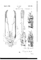
These and still other objects of my invention whereby an improved, highly eicient cutter is provided, will become more apparent-from the following description, wherein reference is made to the accompa'n 'ng drawings, forming a part of this speci catlon and wherein: i .f v n Fig. 1 is a plan view of acutter embodying the principles of my invention, certain hidden parts being shown by dotted lines and an alternate position of the handles also indicated by dotted lines, and wherein a section of cable armor is also shown by dotted lines, the cutterstbeing shown in a closed position;
Fig. 2 is a side elevational view of the device of Fig. 1; l w' f Fig. 3 is avertical medial sectional view showlng the jaw and cutters in an open position prior to a cutting operation; 1-
Fig. 4 is a view similar to Fig. 3 but with the cutter adjusted to receive an armor of the larger type;
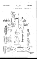
Fig. 5 is a so-called exploded view of the said cutter, the parts thereof being shown in side elevation and in their pro er relative positions prior to assembling, t e ends .of the handles being indicated as broken away;
Figs. 6, 7, and 8 are fra entary plan views of the jaw and armore cable therein. The relative positions of the cutter blades are shown respectively at the start and `at the end of the cutting operation;
Fig. 9 is a bottom plan view of the jaw;
Fig. 10 is a plan view of an adjustable` index plate;
Fig. 11 is a plan view of an adjusting dog;
Fig. 12y is an elevational view of a fragment of armor showing the cut made by the cutter;
Fig. 13 is an elevational view showing the two parts separated.
Referring now to the different figures of drawings wherein like parts are designated 1 by likereferenoe characters, a pair of operating levers or handles 2, provided with hand grips 3 at their free ends, in complementary pairs, have ends 4, adapted to support the gripping and cutting mechanism.
The operative end is broadened and is provided with a camming edge surface at 6, the pur ose of which is later more fully described. The ends 4 are also adapted to be laterall superposed, each of the opposing adjacent aces beingrelieved to form a blade receiving recess for one of the two complementary cutter blades 8.
Each of the recesses is provided with an end wall 9 against which the butt 10 of the cutter blade abuts. The cutter blades are alike and are best shown in Figs. 5 to 8 inelusive, and are preferably of tool steel, each having a cutting edge 11 disposed opposite the butt side 10.`
- Each blade is apertured at 12, and a bearing bolt 13 is disposed therethrough being also extended throu h the apertures of the handles, to hold the lades on the handles.
The bolt has a head 14 at one end and a central threaded bore 15 adapted to receive the threaded end 16 of a ca screw 17. It also has a smooth exterior surace which acts as the pivot bearing for the handles and blades and is of such a length that when the sere-w 17 is tightly screwed therein secured in superosed relation, the parts may still move reely.
A jaw 18 and index plate 19 are also secured to the levers in superposed relation by the bolt 13. The jaw, as best shown in Figs. 5, 7 and 9, comprises a substantially rectangular portion 20 which has anv upstanding abutment 21 at one end. The inner face 22 of the abutment has a plurality of grooves 23 adapted to conform to the contour of an armored cable. A pair of elongated apertures 24 and 25k extend through thek intermediate flat surface of the jaw, the bolt 13 extending through the aperture 24 and securing the jaw slidably to the handles. The upper face of the jaw is machined to provide a smooth flat surface which allows the plate 19 to be slid freely thereby.
The plate '19 is provided with an elongated aperture 26 in its mid-portion through which the bolt 13 is disposed and which allows the plate to slide longitudinally on the jaw. A screw threaded aperture 27 is also provided adapted to receive therein a post 28, which is threaded at its lower end 29 and provided with a smooth surface adjacent the head, adapted to have telescoped thereon a pair of like cylindrical cam rollers 30, and is locked to the plate 19 by lock nut 31 which has a relatively long shank 32, adapted to extend through the aperture in the jaw element aidhlock the screw 28 securely to the plate 19 with the rollers freely rotatable thereon and with the post adapted to slide with the plate longitudinally ofthe jaw.
The upper edge of the plate 19 adjacent the jaw 21 has a beveled surface 33 which is adapted to support the cable armor prior to the cut-ting operation.
An adjusting dog 34 is provided which l comprises a plate having a plurality of machined edges such as 35, 36 and 37 and which has a short thumb piece or lever 38 for moving the same. Each of the sides is positioned at a different distance from an intermediate aperture 39. The dog is pivotally secured to the jaw element, adjacent the end of the plate 19, by a screw 40, and may be rotated about the pivot to present a selected surface against the end portion 41 of the plate 19 preventing further longitudinal movement of the plate in the direction of the ''he jaw element has a longitudinal disposed bore 42 extending between the slot 24 and the end of the jaw parallel to the flat upper surface. A plunger 43 is disposed in the bore and is'spring pressed' toward the aperture 24 by helical spring 44. A cap 45 which has a guide stem l46 for the spring, is screw threaded into the end of the bore retaining the spring and plunger in spring pressed relation with the plunger abutting bolt 13. The pressure upon the bolt 13 tends to force the jaw forward longitudinally relative to the handles. The forward position of the jaw being adjustablylimited by the posi tion of the dog 34. The pressure of t-he plunger 42 upon the post 13 is transmitted to the handles, retaining the camming faces 6 thereon in contact with the cam rollers 30.
When it is desired to `cut the armor of a conduit, the dog 34 is first set to the correct position for the size of the armor to be cut.
The handles or levers are then spread apart,
the armor and the convolutions of the cablev will engage the corresponding grooves 23 in the iaw element.
The relative position of the cutter blades and the armor is best shown in Figs. 3 and 6, the armor beingI supported by the bevelled edge 33 of the plate 19 which is retained in an adjusted position by the dog 34.
The handles are then forced towards each other causing the rollers 30 to be forced from the notches 47, which draw the jaw andarmor toward the cutter blades, after which they ride upon the surface 6. The notch 47 is of such a'depth as to cause the jaw and armor toA be drawn toward the blades into contact therewith.
With the tool constructed as described, the
dles toward each other moves the blades in the radius of a circle with the bearing bolt 13 as the pivot, the cam surface 6 being concentric to the bolt 13, preventing further longitudinal movement ofthe vjaw relative to the handles and blades.
The blades engage the armor, pressing the armor into the grooves of the jaw, the com-A bination of the jaw on one side and blades on the other` forming a vise holding the -armor immovable in any direction. The
blades engage the armor wall as shown in Fig. 8 at the base of two adjacent convolutions.
The blades are forced into the armor and cut through it from opposite sides of the convolutions cutting from the armor, through one and one-half convolutions, a ribbonlike section, best shown in Figs. 8 and 12.
The handles are then spread and the armor removed from the cutter after which the sections of the armor may be parted by unscrewing the same about a half turn, the disconnected armor being shown in Fig. 13. The armor is left in such a condition as to be ready for insertion into a 'proper fitting for junction box assembly without further operations thereon. v
The cutter blades may be readily replaced by unscrewing the' cap screw 17 from the bolt 13 and inserting new blades. The indexing dog 34 may be provided with a suitable indicia as A B and C adjacent to the surfaces 35, 36 and 37 to indicate the size of armor for which the tool is set to cut. The dog may be readily shifted when the arms are in the spread position and causes the jaw to be advanced toward or retarded from the cutter blades and plate 19, two different adjusted positions for the two separate arL mors being' shown in Figs. 3 and 4 respec tively.
Having thus described my inventlon, I am aware that numerous and extensive departures may be made from the embodiment herein illustrated and described but without departing from the spirit of my invention.
I claim:
l. In a lcutter for articulated tubular armor, the combination with a pair of pivoted handles, a cutter blade carried at the forward end of each handle, a reciprocating element slidably supported by the handles and terminating in an armor engagingjaw posi-V tioned beyond and spaced from the forward ends of said blades, and means operative reponsive to relative pivotal movement of the handles to effect a shearing movement of the blades and an vinward movement of said jaw toward said blades during a part only of said shearing movement.
2. A cutter for articulated tubular conduit comprising a pair of cutting plier blades, pivoted handles for effecting a plier cuttin movement of the blades, a reciprocable bloc slidably carried by the handles rovided with a jaw at its forward end, saidp jaw adapted for disposition on the opposite side of a piecev of conduit relative to said blades, and camming means operable responsive t`o a blade operating movement of said handles adapted to bring the blades and jaw closer together to hold the conduit in substantially fixed 0perative relation to the-blades, said blades being so related to said handles as to perform a shearing operation on a wall of said conduit, responsive to a continued movement of said handles.
3. In a cutter for articulated metallic tubular cable, the combination with a jaw element comprising a body portion and an abutment portion, a pair of cutting plier elements, each comprising a forwardly disposed cutting blade and a rearwardly extending handle, means for yieldably securing the forward end portions of said plier-elements and said body portion together, the abutment being disposed in spaced relation to said blades, means responsive to a blade opening movement of said plier handles, comprising :a spring for relatively reciprocating said plier elements and said jaw element to move the abutment farther from the blades, and means responsive to a blade closing handle movement to move the abutment toward the blades.
r 4. `In a cutter for articulated metallic tubular cable, the combination with a jaw element comprising a body pbrtion and an abutment portion, a pair of cutting plier elements, each comprising a forwardly disposed cutting blade and a rearwardly extending handle, means for yieldably securing the forward end portions. o said plier elements and said body portion together, the abutment being disposed in spaced relation to said blades, means responsive to a blade opening movement of said plier handles, comprising a spring for relatively reciprocating said plier elements and said jaw element to move the abutment farther from the blades, and means responsive vto an initial blade closing handle movement to move the abutment toward the blades, and means .to support said jaw element in a substantially lixed spaced position relative to `said'blades during the concluding portion of ting blade anda rearwardly extending b andle means for yieldably securing the forward en portions of said plier elements and said shaped block, having ashorter arm with itsy innergsurface so formedas to provide a conduit engaging jaw, a projecting inwardly from an end portlonv of the longer arm, a pair of plierl cutting elements comprising a pair of rearwardly extending handles and a pair-of forwardly extending cutting blades, a bolt? rejected througli the forward portions fo said plier elements to pivotally join them together, said longer arm being intermediatel apertured,l an extension of the bolt projecte loosely through the arm aperture andterminating in a; retaining. head, said elements provided with camming' edge surfaces dis osed rearwardly of their blades adapted or camming enga ement with said post, spring means adapte to continuously exert a resilient pressure effort tending to maintain the cammingeedgesof said plier elements in engagement with said ost and to maintain the jaw in proper space relation to the blades.
7. In a plier cutter for articulated metallic conduit, thecombination with a attened L-shaped block, having a shorter arm with its inner surface so formed as to provide a conduit engaging jaw, a slide plate, a post projecting inwardly from an end portion of the slide plate, a pair of plier cutting elements comprising a pair of rearwardly extending handles and a pair of forwardly extending cutting blades, said plate su erposed on the inner surface of the block, ab jected through the forward portions of said plier elements to pivotally join them together, said longer arm and said slide plate being apertured, an extension of the bolt project-- ed loosely through the arm and plateapertures and terminating in a retaining head disposed on the outer surface of the longer arm, said elements provided with camming edge surfaces disposed rearwardly of their blades adapted forl camming enga ement with said post, spring means adapte to ycontinuously exert a resllient pressureefort tending to 'maintain the camming edges of said plier elements in engagement with said vostand to maintain the jaw in proper space relation to the blades, and means for adjusting'said plate on said block to fixedly adjust the norolt pron mal spacing between said jaw and said blades. 8. Al plier for longitudinally slitting a generally cylindrical article, comprising a pair of pivotall connected handles, shear blades supported y said handles, and a -j aw element carried thereby, having a aw projected forwardly of the ends of the blades and adapted to restrain movement of the work from the blades during engagement of the blades therewith, and means associated with said handles and said jaw element adapted to effect inward movement of the jaw to a. fixed position relative to the blades during operative movement of said handles.
f 9. A plier for longitudinally slitting a tubular article, comprising a pair of pivotally connected handles shear blades supported by said handles and a jaw element non-rotatably carried thereby, having a jaw projected forwardly of the ends of the blades and adapted to restrain movement of the work from the blades during engagement of the blades therewith, and means associated with said handles and said jaw element, adapted to effect inward movement of the jaw to a fixed position relative to the blades during operative movement of said handles.
1 0. A plier for longitudinally slitting a tubular article, comprising a pair of pivotally connected handles shear blades supported bv said handles and a jaw element non-rotatably carried thereby, having a jaw projected forwardly of the ends of the blades and adapted to restrain movement of the work from the blades during engagement of the blades therewith, and means associated with said handles and said jaw element, adapted to effect an inward movement of said jaw toward the end of the blades during a part only of an operative movement of said handles.
11. A cutter comprising a pair of cutting pliers and a jaw disposed longitudinally in front of the cutters thereof and spaced-therefrom, and means associated with said aw and pliers to cause said jaw and cutters to ef- 110 fect a relative approaching movement responsive to a closing movement of said pliers, said means includingmeans to hold said jaw stationary, relatively to the cutters, after a preliminary operation of said pliers and while the cutting operation thereof is continued.
12, A cutter comprising a pair of plier elements, each having a handle portion at .one end and a forwardly projecting cutter blade portion at the other end, said plier'elements 120 eing pivotally secured together near to but rearwardly of said cutter blade portions projecting forwardly thereof, an article retainlng jaw positioned forwardly of the forwardly disposed ends of said cutter blades, and means interconnecting said plier elements and said jaw adapted to retract the jaw rearwardly responsive to relatively approaching movements of said handle portions, said meansin- .cluding a movement transmission means to 13 cause substantially all of the movement of thel jaw to occur during the first part of the approaching movements of the handle portions.
13. A cutter comprising a pair of plier elements, each havin a handle portion at one end and a forwar ly projecting cutter blade portion at the other end, said plier elements being pivotally secured together near to but rearwardly of said cutter b ade portions projecting forwardly thereof, an article retaining jaw positioned forwardly of the forwardly disposed ends of said cutter blades, and means interconnecting said plier elements and said jaw adapted to retract the jaw rearwardly responsive to relatively approachin movements of said handle port1ons, sai means including a cam and a cam follower to cause substantiall all of the movement of the jaw to occur uring the first part of the approaching movements of the handle portions.
14. A cutter comprising a pair of plier elements, each havin a handle "portion at one end and a. forwar y projecting cutter blade portion at the other end, said plier elements being pivotally secured together near to but rearwardly of said cutter blade portions projecting forwardly thereof, an article retaining 'aw positioned forwardly of the forwardly isposed ends of said cutter blades, and means interconnecting said plier elements and said jaw adapted to retract the jaw rearwardly responsive to relatively approaching movements of said handle portions, said means includin a cam follower and a cam having a surface ormed to cause substantially all of the movement of the 'j aw to occur during the first part of the approaching movements of the handle portions. i
In testimony whereof I hereunto affix my signature this 10th day of May, 1929.
WILLIAM C. ROE.
Priority Applications (1)
| Application Number | Priority Date | Filing Date | Title |
|---|---|---|---|
| US364218A US1851985A (en) | 1929-05-18 | 1929-05-18 | Cutter |
Applications Claiming Priority (1)
| Application Number | Priority Date | Filing Date | Title |
|---|---|---|---|
| US364218A US1851985A (en) | 1929-05-18 | 1929-05-18 | Cutter |
Publications (1)
| Publication Number | Publication Date |
|---|---|
| US1851985A true US1851985A (en) | 1932-04-05 |
Family
ID=23433559
Family Applications (1)
| Application Number | Title | Priority Date | Filing Date |
|---|---|---|---|
| US364218A Expired - Lifetime US1851985A (en) | 1929-05-18 | 1929-05-18 | Cutter |
Country Status (1)
| Country | Link |
|---|---|
| US (1) | US1851985A (en) |
-
1929
- 1929-05-18 US US364218A patent/US1851985A/en not_active Expired - Lifetime
Similar Documents
| Publication | Publication Date | Title |
|---|---|---|
| US3596541A (en) | Wire stripping tools | |
| US2674796A (en) | Pivoted utility cutting tool having a latching mechanism | |
| US4945788A (en) | Adjustable-mid-span stripper for wire and cable | |
| US3831207A (en) | Multipurpose pliers | |
| US3309948A (en) | Wire cutting and stripping apparatus adjustable for sizes and lengths of wire to be stripped | |
| US2313793A (en) | Wire stripping tool | |
| US2141002A (en) | Cable stripper | |
| US12294204B2 (en) | Armored cable stripping tool for cutting the armor in two places | |
| US2683930A (en) | Cable vise and cutter for removing armor from cable | |
| US3238618A (en) | Electric cable insulation cutter | |
| CN218633074U (en) | A wire stripper capable of cutting cables | |
| US3171199A (en) | Blade type plastic tube cutter with blade guiding means | |
| US2179581A (en) | Wire stripper hand tool | |
| US3125908A (en) | rozmus | |
| US2217077A (en) | Wire insulation cutting and stripping device | |
| US1851985A (en) | Cutter | |
| US20220193941A1 (en) | Ratcheting pvc cutter with quick release blade mechanism | |
| US1902913A (en) | Pliers | |
| US2642658A (en) | Cutting tool for cutting sheet metal | |
| US3731561A (en) | Mechanism for severing and simultaneously stripping wires covered by a sheet | |
| US1866426A (en) | Combination wrench | |
| US2273376A (en) | Cutting tool | |
| US2817898A (en) | Pipe cutters | |
| US2465694A (en) | Combined comb and clipper | |
| US2230030A (en) | Tool |