US185196A - Improvement in side-bar vehicles - Google Patents
Improvement in side-bar vehicles Download PDFInfo
- Publication number
- US185196A US185196A US185196DA US185196A US 185196 A US185196 A US 185196A US 185196D A US185196D A US 185196DA US 185196 A US185196 A US 185196A
- Authority
- US
- United States
- Prior art keywords
- bar
- improvement
- vehicles
- vehicle
- bar vehicles
- Prior art date
- Legal status (The legal status is an assumption and is not a legal conclusion. Google has not performed a legal analysis and makes no representation as to the accuracy of the status listed.)
- Expired - Lifetime
Links
Images
Classifications
-
- B—PERFORMING OPERATIONS; TRANSPORTING
- B60—VEHICLES IN GENERAL
- B60G—VEHICLE SUSPENSION ARRANGEMENTS
- B60G11/00—Resilient suspensions characterised by arrangement, location or kind of springs
- B60G11/02—Resilient suspensions characterised by arrangement, location or kind of springs having leaf springs only
- B60G11/10—Resilient suspensions characterised by arrangement, location or kind of springs having leaf springs only characterised by means specially adapted for attaching the spring to axle or sprung part of the vehicle
- B60G11/12—Links, pins, or bushes
Definitions
- My invention consists in the peculiar construction and application of wood or metal side bars and reaches, combined with and connecting both axles.
- the object of my invention is to construct a cheap, durable, and efficient vehicle, and it -will be observed that I dispense with many pieces that are generally used in the construction of vehicles, and consequently the weight and expense of the same are considerably more substantial and durable article produced.
- A represents the ordinary wheels of a vehicle;
- A the axles of the same.
- B represents my improved combination of side bar and reach, or reaches of one piece of wood or metal, bentor formed so as to connect both axlesgmd in this instance is a T-shaped bar, forme in the shape of the letter U, so that when in position upon the axles the flat or broadest part of the bar comes upon the same.
- a is a piece of wood provided with a metal face, which acts as a rocker-iron on the axle.
- the head of the king-bolt is sunk into the wood, and then the piece is secured to the under side of the bar, which holds the bolt firmly in position and prevents rattling.
- the bolt then passes through the axle in the ordinary manner.
- the opposite ends of the bar are secured to the rear axle.
- a is a safety-clip passing under the front axle, the ends being secured to the bar or Wooden block between rocker-plate and the bar, so that in case the king-bolt breaks the clip will prevent the front axle from drawing from under the box.
- bb are stirrups secured to the under side of the bar, and receiving the ends of the springs 11 b.
- the bent bar 13 for connecting the front and rear axles and supporting the body
Landscapes
- Engineering & Computer Science (AREA)
- Mechanical Engineering (AREA)
- Vehicle Step Arrangements And Article Storage (AREA)
Description
1 .1. new. SIDE-BAR VEHICLE.
6 7 8 1- 2 1- m D d Patente lessened, and at the same time a Urrn STATES Fries;
IMPROVEMENT IN SIDE-BAR VEHICLES.
Specification forming part of Letters Patent No. I 85,196, dated December 12, 1876; application filed April 1, 1876.
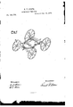
To all whom it may concern Be it known that I, FRANK P. STONE, of the city ofOhicago, in the county of Cook and State of Illinois, have invented certain new and useful Improvements in Vehicles; and I do hereby declare the following to be a full, clear, and exact description thereof, which will enable others skilled in the art to which my invention relates to make and use the same, reference being had to the accompanying drawing, forming part of this specification, in which Figure 1 is a perspective of the running-gear of a vehicle embodying my improvement.
My invention consists in the peculiar construction and application of wood or metal side bars and reaches, combined with and connecting both axles.
The object of my invention is to construct a cheap, durable, and efficient vehicle, and it -will be observed that I dispense with many pieces that are generally used in the construction of vehicles, and consequently the weight and expense of the same are considerably more substantial and durable article produced.
In the accompanying drawing, A represents the ordinary wheels of a vehicle; A, the axles of the same. B represents my improved combination of side bar and reach, or reaches of one piece of wood or metal, bentor formed so as to connect both axlesgmd in this instance is a T-shaped bar, forme in the shape of the letter U, so that when in position upon the axles the flat or broadest part of the bar comes upon the same.
a is a piece of wood provided with a metal face, which acts as a rocker-iron on the axle. The head of the king-bolt is sunk into the wood, and then the piece is secured to the under side of the bar, which holds the bolt firmly in position and prevents rattling. The bolt then passes through the axle in the ordinary manner. The opposite ends of the bar are secured to the rear axle.
a is a safety-clip passing under the front axle, the ends being secured to the bar or Wooden block between rocker-plate and the bar, so that in case the king-bolt breaks the clip will prevent the front axle from drawing from under the box. bb are stirrups secured to the under side of the bar, and receiving the ends of the springs 11 b.
It is plain to be seen that a vehicle constructed in this manner consumes less time and material in its construction than by the ordinary manner.
Having thus described my in ention, what I claim as new, and desire to secure by Letters Patent, is-
As an improvement in the construction of vehicles, the bent bar 13, for connecting the front and rear axles and supporting the body,
substantially as set forth.
The above specification signed by me this 18th day of November, 1875.
FRANK P. STONE.
Witnesses:
B. D. INGERSOLL, S. J. STOW.
Publications (1)
| Publication Number | Publication Date |
|---|---|
| US185196A true US185196A (en) | 1876-12-12 |
Family
ID=2254601
Family Applications (1)
| Application Number | Title | Priority Date | Filing Date |
|---|---|---|---|
| US185196D Expired - Lifetime US185196A (en) | Improvement in side-bar vehicles |
Country Status (1)
| Country | Link |
|---|---|
| US (1) | US185196A (en) |
-
0
- US US185196D patent/US185196A/en not_active Expired - Lifetime
Similar Documents
| Publication | Publication Date | Title |
|---|---|---|
| US185196A (en) | Improvement in side-bar vehicles | |
| US639013A (en) | Vehicle-body loop. | |
| US243436A (en) | Oscillating vehicle-gear | |
| US282733A (en) | Running-gear for vehicles | |
| US244008A (en) | Jacob g | |
| US333271A (en) | Side-bar vehicle | |
| US221631A (en) | Improvement in sulkies | |
| US11490A (en) | Spring-body carriage | |
| US348642A (en) | Vehicle running-gear | |
| US173245A (en) | Improvement in spring saddle-clips | |
| US121378A (en) | Improvement in wagons | |
| US204360A (en) | Improvement in vehicle-springs | |
| US685629A (en) | Fifth-wheel. | |
| US159117A (en) | Improvement in fifth-wheels for vehicles | |
| US395463A (en) | Vehicle-spring | |
| US758878A (en) | Means for connecting running-gears to vehicle-bodies. | |
| US297543A (en) | Two-wheeled vehicle | |
| US356358A (en) | Wagon-spring | |
| US203212A (en) | Improvement in vehicle-springs | |
| US597225A (en) | Spring-shackle for vehicles | |
| US324342A (en) | Heebeet m | |
| US186883A (en) | Improvement in vehicle-springs | |
| US341216A (en) | Maetih l | |
| US199646A (en) | Improvement in carriage-springs | |
| US414534A (en) | Charles |