US1851964A - Type or matrix for typographical composing machines - Google Patents
Type or matrix for typographical composing machines Download PDFInfo
- Publication number
- US1851964A US1851964A US415665A US41566529A US1851964A US 1851964 A US1851964 A US 1851964A US 415665 A US415665 A US 415665A US 41566529 A US41566529 A US 41566529A US 1851964 A US1851964 A US 1851964A
- Authority
- US
- United States
- Prior art keywords
- matrices
- matrix
- elevator
- ears
- rail
- Prior art date
- Legal status (The legal status is an assumption and is not a legal conclusion. Google has not performed a legal analysis and makes no representation as to the accuracy of the status listed.)
- Expired - Lifetime
Links
- 239000011159 matrix material Substances 0.000 title description 32
- 210000005069 ears Anatomy 0.000 description 33
- 238000005266 casting Methods 0.000 description 5
- 230000002459 sustained effect Effects 0.000 description 4
- 102100023170 Nuclear receptor subfamily 1 group D member 1 Human genes 0.000 description 3
- 230000006378 damage Effects 0.000 description 2
- 208000027418 Wounds and injury Diseases 0.000 description 1
- 238000010276 construction Methods 0.000 description 1
- 230000000994 depressogenic effect Effects 0.000 description 1
- 238000006073 displacement reaction Methods 0.000 description 1
- 208000014674 injury Diseases 0.000 description 1
- 239000002184 metal Substances 0.000 description 1
- 230000008520 organization Effects 0.000 description 1
- 230000000284 resting effect Effects 0.000 description 1
- 230000000717 retained effect Effects 0.000 description 1
Images

Classifications
-
- B—PERFORMING OPERATIONS; TRANSPORTING
- B41—PRINTING; LINING MACHINES; TYPEWRITERS; STAMPS
- B41B—MACHINES OR ACCESSORIES FOR MAKING, SETTING, OR DISTRIBUTING TYPE; TYPE; PHOTOGRAPHIC OR PHOTOELECTRIC COMPOSING DEVICES
- B41B11/00—Details of, or accessories for, machines for mechanical composition using matrices for individual characters which are selected and assembled for type casting or moulding
Definitions
- This invention relates to typographical composing machines, such as linotype machines of the general organization represented in U. S. Letters Patent to O. Mergenthaler,
- class of machines designed to handle matrices provided with two or more superposed characters, and wherein the assembling elevator, intermediatechannel, and first elevator are each provided with two sets of supporting rails whereby the matrices may be composed and maintained at an upper or lower level, or both, as desired, to locate the selected characters in operative position.
- the present invention is intended to overcome the above objection and aims to provide head-letter or display matrices which will'always be assembled in the lower position without regard to the adjustment of the machine parts, that is to say, whether the assembler rail and the stop member are either orboth in operative or inoperative position.
- the improved matrices are formed as usual with upper and lower pairs of supporting lugs or. ears (which project from the front and'rear edges of the matrices and are located in the same vertical plane), but the lower front ears, instead of being arranged directly opposite the lower rear ears as customary, are situated at a higher level on the matrix bodies.
- the difference in the level of these lower frontand rear lugs is made to correspond with the distance in level between the upper assembler rail, known as the duplex rail (which is adjustably mounted in the front wall of the assembling elevator and serves to determine the level of the twoletter matrices during composition, as well as to support them intheir upper position), and the lower assembler rails (which are fixed to the front and rear walls of the assembling elevator and support the matrices in their lowerposition). Consequently, when the improved head-letter matrices are composed in line in the assembling elevator, they will 211- ways clear the duplex rail, whether it occupies its operative or projecting position or occupies its inoperative or withdrawn posi- 85 tion.
- the duplex rail which is adjustably mounted in the front wall of the assembling elevator and serves to determine the level of the twoletter matrices during composition, as well as to support them intheir upper position
- the lower assembler rails which are fixed to the front and rear walls of the assembling elevator and support the matric
- the duplex rail cannot intercept the incoming matrices, due to the raised position of their front lower ears, and the matrices therefore pass onto the lower fixed rails where they are supported in the lower position as required.
- the action of the parts is as though the lower front ears'of the matrices were entirely omitted, as might actually be done, so that the matrices are in- 95 capable of support in the assembling elevator except in the lower position.
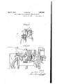
- Fig. 1 is a front elevation of a portion of a linotype machine equipped with the improved matrices
- Fig. 2' is a perspective view showing by comparison a regular two-letter matrix and an improved head-letter matrix, the former being shown at two different composing levels and the latter at a single (lower) level;
- Fig. 3 is a vertical section through the upper portion of the assembling elevator, showing by the full lines animproved matrix assembled at the lower level therein and by the dotted lines a regular two-letter matrix assembled at the upper level;
- Fig. 4 is a vertical section through the casting mechanism showing the first elevator supporting a line of the improved matrices in operative relation to the mold.
- the regular two-letter matrices X and the single letter display matrices Y are stored in the respective magazines A, A and are adapted to be released therefrom in the usual way by the manipulation of the keyboard B, whence they pass into the assembling elevator C wherein they are composed in line.
- the elevator C is raised into registration with the intermediate channel D, such movement of theelevator tripping the transfer carriage E, which thereupon shifts the composed line to the left into the first elevator or transporter F.
- the first elevator then descends to locate the line before the casting mold G, which immediately advances from the rear into en gagement therewith preparatory to the casting operation, all as well understood in the art.
- the first elevator F are each provided with two sets of supporting rails for sustaining the matrices at the upper or lower level, as
- the mold G (herein shown as of the recessed variety used only for casting from the larger or head-letter matrices Y) is formed with a single horizontal groove G wherein the rear or aligning ears 3 of these matrices engage, whereas the type of mold most commonly employed is provided with two such grooves, in one or the other of which the aligning ears of the regular two-letter matrices engage according to the level at which they are sustained in the first elevator.
- the first elevator F is allowed to descend to its lowermost position as determined by the engagement of its set screw F with the top of the vise frame H.
- a second set screw F with which the elevator is also provided is adapted to engage and depress the vise automatic H, as the elevator comes to rest so that the cycle of the operation may continue.
- the machine is usually equipped with a stop member J which may be thrown into action at will to arrest the elevator in a raised position with reference to the mold G as shown in Fig. 4:, but when the elevator is thus arrested, it is necessary that the matrices be sustained therein at the lower level, as otherwise the objections before mentioned will arise.
- the improved head-letter or display matrices Y are identical in form or contour with the regular two-letter matrices X except as to location of their lower front ears.
- the in'iproved matrix Y is formed at the top and on its front and rear edges with projecting ears y (also the customary distributing combination 3 and at the bottom and on its front and rear edges in AU with projectingears y and g respectively.
- t e lowerfront ear :2/ of the improved matrix Y is located on the matrix body at a higher level than the rear ear 1 thus distinguishing from the regular matrix X whose lower earsa: are arranged directly opposite each other or at the same level. It is this difference in location of the ear g which constitutes the essenceof the present invention.
- the matrix is so formed that its lower front car i will stand above the upper rail C while its lower rear ear y will rest upon the rear one of the lower rails C
- the matrices Y can only be composed in the assembling elevator at one level, namely, the lower level, even though the rail C may be set in its projected or operative position, as in Fig. 3.
- the regular two-letter matrices X on the other hand, they will be composed at the upper or lower level in the assembling ele vator according to the position of the rail 0
- the dot-ted lines show a twoletter matrix X as supported at the upper level by the rail 0 this being due to the nonraised location of its lower front ear.
- the ears 3 (which as previously stated are arranged in the same vertical plane with the other ears) are very useful in effecting the distribution of the matrices into their storage magazine, since they not only cooperate with threads of the lower distributor screw of the set usually employed for propelling the matrices along the distributor bar, but also serve to guide the matrices into and through their respective magazine channels after they drop from the bar.
- vise automatic H is depressed and the mold advanced into engagement with the line preparatory to 'justification and the casting of the slug.
- the invention has been herein shown merelyf-in preferred form and as applied to a standard linotype matrix, but obviouslymany changes and variations may be made therein which will still be comprised within its spirit. For example, it might be adapted to other forms of matrices or to other kinds of typographical machines, such as those which handle type or dies instead of matrices. It should, therefore,be understood that the invention is not limited to any specific formor embodiment except insofar as such limita tions are specified in the claims.
- a type or matrix formed at its lower end with a pair of projectingears located respectively at relatively different levels on the front and rearedges thereof.
- a type or matrix formed at its lower end with a pair of ears projecting from the front and rear edges of the matrix, the level V of the front projecting car being definitely higher than that of the rear projecting ear;
- a type ormatrix formed at its lower end and on its front and rear edges with a pair of projecting ears, one of said ears being located at the bottom of the matrix and the other being located at a definitely higher.
- a type or matrix formed with upper and lower pairs of ears projecting from its front and rear edges, all of said ears being located in the same vertical plane and the said lower projecting ears being located at relatively different levels, for the purpose described.
- a single character type or matrix formed at its upper end and on'its opposite edges with a pair of projecting ears, and at its lower end and on opposite edges with a pair of projecting ears vertically aligned with the upper ears but located respectivelyv at relatively different levels, for the purpose described.
- a typographical machine equipped with single character matrices and provided with an assembling elevator having an upper front rail and a lower rear rail for supporting twoletter matrices at respectively different levels, the said single'character matrices each being formed at the bottom and on its rear edge with a projecting ear adapted to engage the said lower rail and having a portion of its front edge so disposed that it lies in front of a vertical plane passing through the rear edge of the said upper rail.
- a typographical machine equipped with single character matrices and provided with an assembling elevator having an upper front rail and a lower rear rail for supporting twoletter matrices at respectively different levels, the said single character matrices each being formed at its lower end with a pair of ears projecting from its front and rear edges at relatively different levels so as to cooperate with both of said rails simultaneously, for the purpose described.
- a typographical machine equipped with single character matrices and provided with an assembling elevator having an upper front retractable rail and a lower rear fixed rail for supporting two-letter matrices at'respectively different levels, said single character matrices each being formed at the lower end with an ear projecting from its rear edge and adapted to engage the said lower rail and on its front edge with an ear projecting therefrom at ahigher level and adapted to engage the said upper rail, whereby the matrices may be composed at the lower level irrespective of the presence or absence of the front supporting rail.
- a type or matrix presenting front and.
- the front edge being devoid of a protruding.
Landscapes
- Lift-Guide Devices, And Elevator Ropes And Cables (AREA)
Description
April5, 1932. A, ARCHER 1,851,964
TYPE OR MATRIX FOR TYPOGRAPHICAL COMPOSING MACHINES Filed Dec. 21, 1929 2-Sheets-Sheet 1 BY 1% m? I April 5, 1932. I A. ARCHER TYPE OR MATRIX FOR TYPOGRAPHICAL COMPOSING MACHINES a 2 Sheets-Sheet Filed Dec. 21, 1929 INVENTOR Patented Apr. 5, 1932' UNITED STATES PAT NT; OFFICE ALFRED ARCHER, OF CALDWELL, NEW JERSEY, ASSIGNOR,TO MERGENTHALER.LTNO- TYPE COMPANY, A CORPORATION OF NEW YORK TYPE OR MATRIX FOR TYPOGRAPHICAL COMPOSING MACHINES Application filed December 21, 1929. Serial No. 415,665.
This invention relates to typographical composing machines, such as linotype machines of the general organization represented in U. S. Letters Patent to O. Mergenthaler,
5 No. 436,532, wherein circulating matrices are released from a magazine in the order in which their characters are to appear in print and then composed in line in an assembler or assembling elevator, the composed line then transferred through an intermediate guide or channel into a vertically movable transporter or first elevator which presents it to a mold, whereupon the mold is filled with molten metal to form a slug or linotype against the matrices which produce the type characters thereon, and the matrices thereafter elevated and returned through a distributing mechanism to the magazine from which they started. More particularly, it relates to that class of machines designed to handle matrices provided with two or more superposed characters, and wherein the assembling elevator, intermediatechannel, and first elevator are each provided with two sets of supporting rails whereby the matrices may be composed and maintained at an upper or lower level, or both, as desired, to locate the selected characters in operative position.
In. the use of head-letter, or display matrices, or matrices with single characters above 14: point, it is the usual practice to assemble and maintain such matrices not at the upper level as would. otherwise be required, but at the lower level, and then to arrest the first elevator in a slightly raised position so as to locate the characters opposite the mold slot, such arrest of the elevator being ordinarily effected by a stop member on the vise frame and adapted to be thrown into action at the will of the operator. The foregoing practice has given rise to very serious objections, as it frequently happens that an operator, through oversight or carelessness, will assemble the said matrices at the upper level while the elevator stop is in action, which will result in the improper presentation of the matrix line to: the mold and hence produce a squirt, or cause damage to the parts, or both.
The present invention is intended to overcome the above objection and aims to provide head-letter or display matrices which will'always be assembled in the lower position without regard to the adjustment of the machine parts, that is to say, whether the assembler rail and the stop member are either orboth in operative or inoperative position. 'In the preferred embodiment illustrated,the improved matrices are formed as usual with upper and lower pairs of supporting lugs or. ears (which project from the front and'rear edges of the matrices and are located in the same vertical plane), but the lower front ears, instead of being arranged directly opposite the lower rear ears as customary, are situated at a higher level on the matrix bodies. The difference in the level of these lower frontand rear lugs is made to correspond with the distance in level between the upper assembler rail, known as the duplex rail (which is adjustably mounted in the front wall of the assembling elevator and serves to determine the level of the twoletter matrices during composition, as well as to support them intheir upper position), and the lower assembler rails (which are fixed to the front and rear walls of the assembling elevator and support the matrices in their lowerposition). Consequently, when the improved head-letter matrices are composed in line in the assembling elevator, they will 211- ways clear the duplex rail, whether it occupies its operative or projecting position or occupies its inoperative or withdrawn posi- 85 tion. In the former case, which of course is the only one need be considered, the duplex rail cannot intercept the incoming matrices, due to the raised position of their front lower ears, and the matrices therefore pass onto the lower fixed rails where they are supported in the lower position as required. The action of the parts is as though the lower front ears'of the matrices were entirely omitted, as might actually be done, so that the matrices are in- 95 capable of support in the assembling elevator except in the lower position.
In this connectiomit willbe understood that the ordinary two-letter matrices are not changed in form and cantherefore be commo posed in the assembling elevator in an upper or lower position as before and in exactly the same way. In other words, this invention does not involve any change whatever in the standard machine or in the regular two-letter matrices, but contemplates only a change in the single character head-letter or display matrices, although this change is merely one of location of the lower front ears of such matrices, which otherwise remain the same as heretofore. It is in this simple way that the objections before noted are done away with, making it entirely unnecessary to resort to the use of safety devices or attachments such as are now in use upon the commercial machines. While as above stated the lower front ears might be entirely omitted from the improved matrices, they are retained in their new location in order to enable the matrices to be more readily handled by the various machine elements during their travel or circulation through the machine.
Referring to the drawings:
Fig. 1 is a front elevation of a portion of a linotype machine equipped with the improved matrices; Fig. 2'is a perspective view showing by comparison a regular two-letter matrix and an improved head-letter matrix, the former being shown at two different composing levels and the latter at a single (lower) level;
Fig. 3 is a vertical section through the upper portion of the assembling elevator, showing by the full lines animproved matrix assembled at the lower level therein and by the dotted lines a regular two-letter matrix assembled at the upper level; and
Fig. 4 is a vertical section through the casting mechanism showing the first elevator supporting a line of the improved matrices in operative relation to the mold.
' As shown in Fig. '1, the regular two-letter matrices X and the single letter display matrices Y are stored in the respective magazines A, A and are adapted to be released therefrom in the usual way by the manipulation of the keyboard B, whence they pass into the assembling elevator C wherein they are composed in line. After composition of the line, the elevator C is raised into registration with the intermediate channel D, such movement of theelevator tripping the transfer carriage E, which thereupon shifts the composed line to the left into the first elevator or transporter F. The first elevator then descends to locate the line before the casting mold G, which immediately advances from the rear into en gagement therewith preparatory to the casting operation, all as well understood in the art.
As previously indicated, the assembling elevator C, the intermediate channel I), and
the first elevator F are each provided with two sets of supporting rails for sustaining the matrices at the upper or lower level, as
required. This construction is so well known that no detailed description thereof seems necessary, but, to identify the parts, it may be noted (see the dotted lines, Fig. 3) that the two-letter matrices X aresustained at the upper level in the assembling elevator C by the engagement of their lower front projecting ears m with the retractable duplex rail C or at the lower level by the engagement of both the front and rear lower ears with the fixed supporting rails C Those matrices assembled at the upper level will be sustained in the first elevator F at a corresponding level by the engagement of their lower front ears with the retractable rail F or at the lower level by the engagement of their upper projecting ears m with the fixed rails F (see Fig. 4).
The mold G (herein shown as of the recessed variety used only for casting from the larger or head-letter matrices Y) is formed with a single horizontal groove G wherein the rear or aligning ears 3 of these matrices engage, whereas the type of mold most commonly employed is provided with two such grooves, in one or the other of which the aligning ears of the regular two-letter matrices engage according to the level at which they are sustained in the first elevator.
In the normal operation of the machine,
the first elevator F is allowed to descend to its lowermost position as determined by the engagement of its set screw F with the top of the vise frame H. At the same time, a second set screw F with which the elevator is also provided, is adapted to engage and depress the vise automatic H, as the elevator comes to rest so that the cycle of the operation may continue. However, for reasons previously noted.'the machine is usually equipped with a stop member J which may be thrown into action at will to arrest the elevator in a raised position with reference to the mold G as shown in Fig. 4:, but when the elevator is thus arrested, it is necessary that the matrices be sustained therein at the lower level, as otherwise the objections before mentioned will arise. Thus, if the display matrices Y were sustained at the upper level as indicated by the dotted lines in Fig. l, it is evident that their rear lower ears would fail to engage in the aligning groove G of the mold G as the latter advances from the rear, so that injury to the parts or a bad squirt would necessarily result.
As before stated, the improved head-letter or display matrices Y are identical in form or contour with the regular two-letter matrices X except as to location of their lower front ears. Thus (see Fig. 2) like the regular two-letter matrix X, the in'iproved matrix Y is formed at the top and on its front and rear edges with projecting ears y (also the customary distributing combination 3 and at the bottom and on its front and rear edges in AU with projectingears y and g respectively.
However, it is pointed out that t e lowerfront ear :2/ of the improved matrix Y is located on the matrix body at a higher level than the rear ear 1 thus distinguishing from the regular matrix X whose lower earsa: are arranged directly opposite each other or at the same level. It is this difference in location of the ear g which constitutes the essenceof the present invention.
By reference to Fig. 3, it will be observed that the duplex rail C is projected into the composing channel of the'assembling elevator C and yet that the matrix Y is shown as standingat the lower level in the elevator. This is because of the raised position of the lower front ear 1 whose level above that of the lower rear ear g is fixed according to the different levels of the upper retractable rail C and the lower fixed rails C (see also Fig. 2). In other words, the matrix is so formed that its lower front car i will stand above the upper rail C while its lower rear ear y will rest upon the rear one of the lower rails C Accordingly, the matrices Y can only be composed in the assembling elevator at one level, namely, the lower level, even though the rail C may be set in its projected or operative position, as in Fig. 3. In the case of the regular two-letter matrices X, on the other hand, they will be composed at the upper or lower level in the assembling ele vator according to the position of the rail 0 In Fig. 3, the dot-ted lines show a twoletter matrix X as supported at the upper level by the rail 0 this being due to the nonraised location of its lower front ear.
While in Fig. 3 the lower front car of the matrix Y is shown resting upon the duplex rail C this specific relation of the parts is really not essential, since under normal conditions the matrix, would be main tained in the required upright position by the assembler gate C even though the ear 7 stopped short of the duplex rail C or were indeed entirely eliminated. The presence of this ear, however, is desirable for the reason that (unless the front lower rail C were extended laterally beneath the body of the matrix) the matrix might topple, forward or drop to the floor when the gage C is opened for access to the line (see dotted lines, Fig. 3). As it is. the ear 1 is adapted either to engage the duplex rail, if it happens to be adjusted to its active position as shown in Fig. 3, or to engage the front side wall of the elevator, and thus support the matrices against forward displacement when the gate C is swung down to its inactive position. Moreover, the ears 3 (which as previously stated are arranged in the same vertical plane with the other ears) are very useful in effecting the distribution of the matrices into their storage magazine, since they not only cooperate with threads of the lower distributor screw of the set usually employed for propelling the matrices along the distributor bar, but also serve to guide the matrices into and through their respective magazine channels after they drop from the bar.
It will now be seen that, as the improved matrices Y are being composed," they will I be allowed to pass to the lower level in the assembler elevator C'irrespective of the adjusted position of the "duplex rail C the rear lower ears y being adapted to engage the rear one of the fixed rails C and the front ears 3 at such time clearing the. rail C and serving merely as a potential support which becomes effective when access to the line is desired. After the composed line is shifted horizontally from the assembling elevator G into the first elevator F, the matrices will be supported by their upper projecting earsg upon'the fixed rails F 2 as shown in Fig. 4, the matrices being 'still maintained at the lower level and the lower front ears idly engaging in the cimtomary groove f located immediately above the auxiliary rail F When therefore the first elevator descends and is arrested in its raised position by the engagement of its set screw F with the stop member J, the lower rear or aligning ears 3 of the matrices will be located in proper relation to the mold G (see Fig. 4). As the elevator comes to rest, the
vise automatic H is depressed and the mold advanced into engagement with the line preparatory to 'justification and the casting of the slug.
The invention has been herein shown merelyf-in preferred form and as applied to a standard linotype matrix, but obviouslymany changes and variations may be made therein which will still be comprised within its spirit. For example, it might be adapted to other forms of matrices or to other kinds of typographical machines, such as those which handle type or dies instead of matrices. It should, therefore,be understood that the invention is not limited to any specific formor embodiment except insofar as such limita tions are specified in the claims.
Having thus described my invention, what I claim is: j
1. A type or matrix formed at its lower end with a pair of projectingears located respectively at relatively different levels on the front and rearedges thereof.
2. A type or matrix formed at its lower end with a pair of ears projecting from the front and rear edges of the matrix, the level V of the front projecting car being definitely higher than that of the rear projecting ear;
3. A type ormatrix formed at its lower end and on its front and rear edges with a pair of projecting ears, one of said ears being located at the bottom of the matrix and the other being located at a definitely higher.
level.
: projecting ears located respectively at relatively different levels;
5. A type or matrix formed with upper and lower pairs of ears projecting from its front and rear edges, all of said ears being located in the same vertical plane and the said lower projecting ears being located at relatively different levels, for the purpose described.
6. A, type or matrix as specified in claim 5, characterized by the fact that the lower rear projecting ear is located at the bottom of the matrix and the lower front projecting ear is located at a predetermined higher level. V
7. A single character type or matrix formed at its upper end and on'its opposite edges with a pair of projecting ears, and at its lower end and on opposite edges with a pair of projecting ears vertically aligned with the upper ears but located respectivelyv at relatively different levels, for the purpose described.
8. A typographical machine equipped with single character matrices and provided with an assembling elevator having an upper front rail and a lower rear rail for supporting twoletter matrices at respectively different levels, the said single'character matrices each being formed at the bottom and on its rear edge with a projecting ear adapted to engage the said lower rail and having a portion of its front edge so disposed that it lies in front of a vertical plane passing through the rear edge of the said upper rail. V A
9. A typographical machine equipped with single character matrices and provided with an assembling elevator having an upper front rail and a lower rear rail for supporting twoletter matrices at respectively different levels, the said single character matrices each being formed at its lower end with a pair of ears projecting from its front and rear edges at relatively different levels so as to cooperate with both of said rails simultaneously, for the purpose described.
10. A typographical machine equipped with single character matrices and provided with an assembling elevator having an upper front retractable rail and a lower rear fixed rail for supporting two-letter matrices at'respectively different levels, said single character matrices each being formed at the lower end with an ear projecting from its rear edge and adapted to engage the said lower rail and on its front edge with an ear projecting therefrom at ahigher level and adapted to engage the said upper rail, whereby the matrices may be composed at the lower level irrespective of the presence or absence of the front supporting rail.
11. A type or matrix presenting front and.
the front edge being devoid of a protruding.
ear located at the same level as the car on its rear edge. p
In testimony whereof, this specification has been duly signed.
ALFRED ARCHER.
Priority Applications (1)
| Application Number | Priority Date | Filing Date | Title |
|---|---|---|---|
| US415665A US1851964A (en) | 1929-12-21 | 1929-12-21 | Type or matrix for typographical composing machines |
Applications Claiming Priority (1)
| Application Number | Priority Date | Filing Date | Title |
|---|---|---|---|
| US415665A US1851964A (en) | 1929-12-21 | 1929-12-21 | Type or matrix for typographical composing machines |
Publications (1)
| Publication Number | Publication Date |
|---|---|
| US1851964A true US1851964A (en) | 1932-04-05 |
Family
ID=23646661
Family Applications (1)
| Application Number | Title | Priority Date | Filing Date |
|---|---|---|---|
| US415665A Expired - Lifetime US1851964A (en) | 1929-12-21 | 1929-12-21 | Type or matrix for typographical composing machines |
Country Status (1)
| Country | Link |
|---|---|
| US (1) | US1851964A (en) |
-
1929
- 1929-12-21 US US415665A patent/US1851964A/en not_active Expired - Lifetime
Similar Documents
| Publication | Publication Date | Title |
|---|---|---|
| US1851964A (en) | Type or matrix for typographical composing machines | |
| US2074511A (en) | Typographical casting machine | |
| US1980110A (en) | Slug casting machine | |
| US1383769A (en) | Typographical machine | |
| US1231912A (en) | Typographical machine. | |
| US1869940A (en) | Typographical composing and casting machine | |
| US2166170A (en) | Slug-casting machine | |
| US1579812A (en) | Typographical composing and casting machine | |
| US1124180A (en) | Line-composing and type-casting machine. | |
| US1960182A (en) | Typographical machine | |
| US2201140A (en) | Typographical composing and casting machine | |
| US1182555A (en) | Typographical machine. | |
| US1804489A (en) | Typographical composing and casting machine | |
| US2293000A (en) | Typographical composing machine | |
| US1085925A (en) | Typographical composing-machine. | |
| US1494231A (en) | Matrix for typographical machines | |
| US1431742A (en) | Typographical machine | |
| US1927236A (en) | Typographical composing, casting, and distributing machine | |
| US2011523A (en) | Typographical casting machine | |
| US2098916A (en) | Typographical matrix | |
| US2708507A (en) | Magazine raising and lowering mechanism for typographical machines | |
| US2368860A (en) | Typographical composing and distributing machine | |
| US890177A (en) | Linotype-machine. | |
| US2639026A (en) | Typographical distributing machine | |
| US2095000A (en) | Typographical casting machine |