US1851960A - Air valve - Google Patents
Air valve Download PDFInfo
- Publication number
- US1851960A US1851960A US231187A US23118727A US1851960A US 1851960 A US1851960 A US 1851960A US 231187 A US231187 A US 231187A US 23118727 A US23118727 A US 23118727A US 1851960 A US1851960 A US 1851960A
- Authority
- US
- United States
- Prior art keywords
- casing
- valve
- float
- outlet
- port
- Prior art date
- Legal status (The legal status is an assumption and is not a legal conclusion. Google has not performed a legal analysis and makes no representation as to the accuracy of the status listed.)
- Expired - Lifetime
Links
- 239000011324 bead Substances 0.000 description 12
- XLYOFNOQVPJJNP-UHFFFAOYSA-N water Substances O XLYOFNOQVPJJNP-UHFFFAOYSA-N 0.000 description 12
- 210000002445 nipple Anatomy 0.000 description 9
- 230000005494 condensation Effects 0.000 description 4
- 238000009833 condensation Methods 0.000 description 4
- 239000012530 fluid Substances 0.000 description 4
- 238000010276 construction Methods 0.000 description 2
- 239000007788 liquid Substances 0.000 description 2
- 229910001369 Brass Inorganic materials 0.000 description 1
- 229910000906 Bronze Inorganic materials 0.000 description 1
- 239000010951 brass Substances 0.000 description 1
- 239000010974 bronze Substances 0.000 description 1
- KUNSUQLRTQLHQQ-UHFFFAOYSA-N copper tin Chemical compound [Cu].[Sn] KUNSUQLRTQLHQQ-UHFFFAOYSA-N 0.000 description 1
- 238000010438 heat treatment Methods 0.000 description 1
- 230000006903 response to temperature Effects 0.000 description 1
- 230000000153 supplemental effect Effects 0.000 description 1
Images
Classifications
-
- F—MECHANICAL ENGINEERING; LIGHTING; HEATING; WEAPONS; BLASTING
- F24—HEATING; RANGES; VENTILATING
- F24D—DOMESTIC- OR SPACE-HEATING SYSTEMS, e.g. CENTRAL HEATING SYSTEMS; DOMESTIC HOT-WATER SUPPLY SYSTEMS; ELEMENTS OR COMPONENTS THEREFOR
- F24D19/00—Details
- F24D19/08—Arrangements for drainage, venting or aerating
- F24D19/081—Arrangements for drainage, venting or aerating for steam heating systems
Definitions
- the invention consists in the improved construction and combination ofparts, to be more fully described hereinafter, and the l5 novelty of which will be particularly pointed out and distinctly claimed.
- Fig. 2 is a horizontal section on the line 2-2 of Fig. 1
- Fig. 3 is a detail section on the line 3-3 of Fig. 2.
- FIG. 1 designates, generally, the casing of an air relief valve comprising a bottom 'member 2 and a top member 3, preferably of brass. 2 in which is a central transverse channel 4 substantially semi-cylindrical in cross-section. Extendingupward from the periphery of the base 2 is a substantially cylindrical side wall 5 having a circular opening 6 therethrough, the lowermost point of said opening being substantially tangent to the channel l. Fixed in the channel 4 is one end 7 of a nipple 8 forming the valve inlet and which is sealed in and projects through the' opening 6. The outer end of the nipple 8.
- the nipple 8 has an aperture 10 in its topside within the member 2 and terminates at its inner end 7 adjacent the longitudinal center line of casing 1.
- a siphon tube 12 having a flange 13 at its inner end within The bottom member 2 has a base the member 2.
- the nipple 8 is 5, 1927. Serial No. 231,187.
- the wall 5 is offset radially near its top to form a shoulder or seat 15 above which is a band or ring 16 of enlarged internal diameter.
- the top member 3 serves as a cap for memher 2 and is substantially cylindrical, having a side wall 17 which converges slightly, as at 18, near its upper end, and then converges sharply, as at 19, to an apex 20 to form the top proper of the cap.
- the external diameter of the top member 3 is substantially equal to the internal diameter of the bottom member 2 so that the top member may be telescoped within the bottom member.
- the wall is bent outwardly or otherwise formed with an external annular bead 22 which provides an internal'annular recess or socket 23.
- the diameter of the bead 22 is preferably made slightly larger than the internal diameter of the band or ring 16 of the bottom member 2.
- top and bottom members 2, 3, respectively, are joined to form the, hollow casing 1 by inserting the'top member3 into the bottom member 2, and then forcing bead 22 within ring 16 until the lower edge 24 of the bead abuts'the shoulder 15, thus forming a tight fit.
- the top edge of the bottom member ,2 is burnished or rolled over the upper edge 25 of bead 22, as at 26.
- a plate or cross-bar 29 Through the midpoint of this cross-bar 29 and in the longitudinal center line ofthe casing 1 is an internally threaded hole 30 in which is threaded a supporting and adjust ing screw '31.
- the ring 32 is compressed-and snapped into the recess 23 and held therein by its own resilience, expanding it outwardly against the side wall 17 of the casing.
- a power element 34 which is prefera-bly a thermostatic float having a side wall 35, preferably cylindrical,: and a rigid upper end wall 36.
- the bottom or lower end of the element 34 is sealed by a diaphragm 37, preferably of spring tempered bronze, which is dished or concave, and preferably corrugated in concentric rings, as at 38, to provide greater flexibility of the diaphragm.
- the element 34 is charged in any well known manner with a suitable volatile fluid which will expand when subjected to steam temperature to act on the diaphragm 37 to force it outward.
- the weight of the volatile charge is insufiicient to prevent free floating of the element 34.
- valve stem 39 Carried rigidly by the end wall 36 is an elongated plunger or valve stem 39 having a valve 40 at its free end, which is adapted to close a port 41 in the apex 20 of member '3 by cooperation with a valve seat 42.
- the element 34, valve stem 39 and valve 40 constitute the valve member.
- the valve member is guided for movement longitudinally of the casing 1 to insure proper seating of valve 41' on its seat 42 by sliding engagement of the side wall 35 of element 34 with the reentrant portions or fingers 33 of the guide member 32.
- the operation of the valve is as follows:
- the adjusting screw 31 is first set during assembly of the valve so that the port 41 will be open, i. e., valve 40 will be off its seat, when the volatile fluid in element 34 is cold and contracts; but screw 31 is so set that the outward movement of the diaphragm 37 acting against screw 31, when the volatile fluid expands in response to temperature of steam in casing 1, Wlll raise the valve member to seat the valve 40 and close the port 41.
- the device is applied to a radiator (not shown) by inserting the syphon tube 12 through the radiator ventand then screwing the nipple 8 tightly into the vent.
- annular passage 34 around the element 34 has been made of large area, and that by employing my novel guide member 32 (see Fig. 2) which occupies a minimum of space within the passage 34 the passage is substantially unrestricted, there being main passages 43 and supplemental passages 44.
- a large separating cham ber 3 provided in the cap 3, which is elongated for this purpose.
- a valve of the character described comprising a substantially cylindrical hollow casing having a bottom member and a top member, one of said members having a radially offset portion adjacent its open end, the other of said members'having an annular external bead of slightly greater external diameter than the internal diameter of said oifset portion, said other member being telescoped within said one member with aforce fit forming atight joint, said casing having an inlet and an outlet, a thermostatic float within said casing, and a valve carried by said float adapted to close said outlet.
- a valve of the character described comprising a substantially cylindrical hollow casing having a bottom member and top member, one of said members having a radially offset portion adjacent its open end, the other of said members having an annular external head of slightly greater external diameter than the internal diameter of said offset portion, said other member being telescoped within said one member with a force fit forming a tight joint, said end of said one member overlying a face of said head to lock said members together, said casing having an inlet and an outlet, at thermostatic float within said casing, and a valve-carried by said float adapted to close said outlet.
- A-valve of the character described comprising a hollow casing having a top member and a bottom member, one of said members being telescoped within the other of said members, said one member having oppositely disposed sockets in the telescoped portion, a cross-bar having its ends respectively seated in said sockets, said bottom member having an inlet, said top member having anoutlet, a
- thermostatic float within said casing and supported on said c1ossbar, and a valve carried by said thermostatic float adapted to close said outlet;
- a valve ofthe character described comprising a hollow casing having a top member and a bottom member, one of said members being telescoped within the other of said members, said one member havingoppositely disposed sockets in the telescoped portion, a cross-bar having its ends respectively seated in said sockets, said cross-bar having a centrally disposed adjustable supporting member, said bottom member having an inlet, said top member having an outlet, a thermostatic float within said casing and supported on said adjustable supporting member, and a valve carried by said thermostatic float adapted to close said outlet.
- a valve of the character described comprising a hollow casing having a top member and a bottom member, one of said members being telescoped within the other of said members, said one member having oppositely disposed sockets in the telescoped portion, a cross-bar having its ends respectively seated in said sockets, said cross-bar having a centrally disposed adjustable supporting member, said bottom member having an inlet, said top member having a port, a thermostatic float within said casing and supported on said adjustable supporting member, guide means within said casing for said thermostatic float, and a valve carried by said thermostatic float adapted to close said port.
- a valve of the character described comprising a hollow casing having an inlet and an outlet, a longitudinally reciprocable valve member within said casing adapted to close said outlet, and means in said casing to guide said valve member, said means being held in positionin said casing by expansion against said casing.
- a valve of the character described comprising a hollow casing having an inlet and an outlet, said outlet having a valve seat, a valve member in said casing adapted to engage said seat to close said outlet, and means within said casing to guide said valve member to its seat, said means comprising a split ring held in position by its expansion against said casmg.
- a valve of the character'described comprising a hollow casing having an inlet and an outlet, a resilient split ring compressed within'said casing and held in position by its outward expansion against said casing, said ring having guide means, and a valve member positioned within said ring and guided in longitudinal movement by said guide means, said valve member being adapted to close said outlet.
- a valve of the character described comprising a hollow casing having an inlet and an outlet, aninternal recess extending around casing and held in position by outward expansion against said casing.
- a valve of the character described comprising a hollow casing having an inlet and an outlet, oppositely disposed socketsinsaid casing, a cross-bar having its ends respectively seated in said sockets, a longitudinally reciprocable thermostatic float within said casing supported on said cross-bar, a valve carried by said thermostatic float to close said outlet, a resilient split ring securedin said casing by outward expansion against said casing, said ring surrounding said thermostatic float, and guide fingers on said ring for said thermostatic float.
- a valve of the character described comprising a hollow casing having an inlet and an outlet, oppositely disposed sockets in said casing, across-bar havingitsends respectively seated in said sockets, an annular recess in said casing above said sockets, a resilient split ring secured in said recess by outward expansion against said casing, said ring having. pairs of oppositely disposed reentrant curved portions, a thermostatic float supported on said cross-bar and projecting through said ringin slideable engagement with said reentrant portions, and a valve car- 1ried bysaid float adapted to close said out- 13.
- a valve of the character described comprising a hollow casing having a top member and a bottom member, one of said members having an annular bead forming an internal annular recess, the other of said members having a radially offset annular portion adjacent its open end forming a sur-' rounding shoulder, said one member being telescoped within said other member with said bead engaging said shoulder, said casing having an inlet, and an outlet, alongi tudina'lly reciprocable valve member within said casing adapted to close said outlet, and guide means for said valve member positioned within said recess.
- a valve of the character described comprising a hollow casing having a top member and a bottom member, one of said members having an annular bead forming an internal annular recess, the other of said members having a radially offset annular portion adjacent its open end forming a surrounding shoulder, said one member being telescoped within said other member with said bead engaging said shoulder, said casing having an inlet and an outlet, oppositely disposed sockets in said top member below said recess, a cross-bar having its ends respectively seated in said sockets, a longitudinally reciprocable valve member within said casing supported by said cross-bar and adapted to close said outlet, and guide means for said valve member positioned within said recess.
- a valve of the character described comprising a hollow casing having a top member and a bottom member, one of said members having an annular bead forming an internal annular recess, the other of said members having a radially ofl'set annular portion adjlacent its 'topedge forming a surrounding shoulder, said one member being telescoped within said bottom member with said bead engaging said shoulder, said casing having an inlet and an outlet, oppositely disposed sockets in said one member below said recess, a cross-bar having its ends respectively seated in said sockets, a thermostatic float supported by said cross-bar and having a valve adapted toclose said outlet, and guide means for said float positioned in said recess and held therein by outward expansion of said guide means against said casing.
- a valve of the character described comprising a hollow casing'defining a float chamber having an inlet, said casing having a top member with anoutlet port and having a bottom member, a float member Within said top member and having valve means cooperable with said port, said float member being'directly subject to liquid level in said chamber such that said float member is lifted by and simultaneously with the rise of liquid level in said casing, and means carried by said top member and supporting said float member.
- a valve of the character comprising a hollow casing having a top member with an outlet port and having a bottom member, a float member within said top member andhaving valve means cooperable with said port, and adjustable means carried by said top member and supporting I said floatmember.
- a valve of the character described comprising a hollow casing having a top member with an outlet port and having a bottom member, a float member within said top member and having valve means cooperable with said port, a cross-bar rigidly fixed in said top member, and an adjustable abutment on said cross-bar and supporting said float member.
- a valve of the character described comprising a hollow casing having a top member with an outlet port and having a bottom member, a float member within said top member and having valve means cooperable with said port, means carried by said top member and supporting said float memher, and guide means cooperating. directly with said float member and positioned with-- in said top member and being independent of said supporting means and said valve means.
Landscapes
- Engineering & Computer Science (AREA)
- Physics & Mathematics (AREA)
- Thermal Sciences (AREA)
- Chemical & Material Sciences (AREA)
- Combustion & Propulsion (AREA)
- Mechanical Engineering (AREA)
- General Engineering & Computer Science (AREA)
- Self-Closing Valves And Venting Or Aerating Valves (AREA)
Description
March 29, 1932. DUFFIELD 1,851,960
AIR VALVE Filed Nov s. 1927 37 1 INVENIZOR. 4.4 0 366% w W ,33 33 BY W 43 l 35 v 3 ATTORNEY.
Patented Mar.'29, 1932 TEiS GEORGE BETHUNE DUFFIELD, or nnrnor'r,
PATENT; OFFICE MICHIGAN, ASSIGNOR TO AMERICAN RADI- ATOR COMPANY, OF NEW YORK, N. Y., A CORPORATION OF NEW JERSEY AIR VALVE Application filed. November radiator and prevent the escape of steam or.
water of condensation therefrom.
. The invention consists in the improved construction and combination ofparts, to be more fully described hereinafter, and the l5 novelty of which will be particularly pointed out and distinctly claimed.
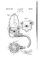
In the accompanying drawings, I have fully and clearly illustrated a preferred embodiment of my invention, to be taken as a part of this specification, and wherein Figure 1 is a vertical central section of the valve;
Fig. 2 is a horizontal section on the line 2-2 of Fig. 1, and 2 Fig. 3 is a detail section on the line 3-3 of Fig. 2.
Referring to the drawings by characters of reference,1 designates, generally, the casing of an air relief valve comprising a bottom 'member 2 and a top member 3, preferably of brass. 2 in which is a central transverse channel 4 substantially semi-cylindrical in cross-section. Extendingupward from the periphery of the base 2 is a substantially cylindrical side wall 5 having a circular opening 6 therethrough, the lowermost point of said opening being substantially tangent to the channel l. Fixed in the channel 4 is one end 7 of a nipple 8 forming the valve inlet and which is sealed in and projects through the' opening 6. The outer end of the nipple 8.
is threaded, as at 9, for connection to a radiator vent. The nipple 8 has an aperture 10 in its topside within the member 2 and terminates at its inner end 7 adjacent the longitudinal center line of casing 1. Through the bore 11 of the nipple 8 is a siphon tube 12 having a flange 13 at its inner end within The bottom member 2 has a base the member 2. At its end 7 the nipple 8 is 5, 1927. Serial No. 231,187.
punched or bent, as at 14, to prevent withdrawal of the siphon tube through the nip-e ple, but'notclamping the tube so as to pre vent rotative and endwise play. The wall 5 is offset radially near its top to form a shoulder or seat 15 above which is a band or ring 16 of enlarged internal diameter.
The top member 3 serves as a cap for memher 2 and is substantially cylindrical, having a side wall 17 which converges slightly, as at 18, near its upper end, and then converges sharply, as at 19, to an apex 20 to form the top proper of the cap. The external diameter of the top member 3 is substantially equal to the internal diameter of the bottom member 2 so that the top member may be telescoped within the bottom member. At a determined distance from the bottom edge 21 of wall 17, the wall is bent outwardly or otherwise formed with an external annular bead 22 which provides an internal'annular recess or socket 23. The diameter of the bead 22 is preferably made slightly larger than the internal diameter of the band or ring 16 of the bottom member 2. The top and bottom members 2, 3, respectively, are joined to form the, hollow casing 1 by inserting the'top member3 into the bottom member 2, and then forcing bead 22 within ring 16 until the lower edge 24 of the bead abuts'the shoulder 15, thus forming a tight fit. In order to lock the members together and to strengthen the joint, the top edge of the bottom member ,2 is burnished or rolled over the upper edge 25 of bead 22, as at 26.
Adjacent the bottom edge 21 of wall 17 I preferably'provide diametrically opposed sockets 27 28 to receive the opposite ends, respectively, of a plate or cross-bar 29. Through the midpoint of this cross-bar 29 and in the longitudinal center line ofthe casing 1 is an internally threaded hole 30 in which is threaded a supporting and adjust ing screw '31. The socket or recess 23, above described, receives a guide member 32, preferably of resilient wire and in the form of a split-ring having ,radially reentrant or inwardly curved portions '33 which serve as guide fingers. The ring 32 is compressed-and snapped into the recess 23 and held therein by its own resilience, expanding it outwardly against the side wall 17 of the casing.
lVithin the casing 1 and supported on the screw 31 is a power element 34 which is prefera-bly a thermostatic float having a side wall 35, preferably cylindrical,: and a rigid upper end wall 36. The bottom or lower end of the element 34 is sealed by a diaphragm 37, preferably of spring tempered bronze, which is dished or concave, and preferably corrugated in concentric rings, as at 38, to provide greater flexibility of the diaphragm. The element 34 is charged in any well known manner with a suitable volatile fluid which will expand when subjected to steam temperature to act on the diaphragm 37 to force it outward. The weight of the volatile charge, however, is insufiicient to prevent free floating of the element 34. Carried rigidly by the end wall 36 is an elongated plunger or valve stem 39 having a valve 40 at its free end, which is adapted to close a port 41 in the apex 20 of member '3 by cooperation with a valve seat 42. The element 34, valve stem 39 and valve 40 constitute the valve member. The valve member is guided for movement longitudinally of the casing 1 to insure proper seating of valve 41' on its seat 42 by sliding engagement of the side wall 35 of element 34 with the reentrant portions or fingers 33 of the guide member 32.
The operation of the valve is as follows: The adjusting screw 31 is first set during assembly of the valve so that the port 41 will be open, i. e., valve 40 will be off its seat, when the volatile fluid in element 34 is cold and contracts; but screw 31 is so set that the outward movement of the diaphragm 37 acting against screw 31, when the volatile fluid expands in response to temperature of steam in casing 1, Wlll raise the valve member to seat the valve 40 and close the port 41. The device is applied to a radiator (not shown) by inserting the syphon tube 12 through the radiator ventand then screwing the nipple 8 tightly into the vent. When steam is admitted to the heating system, which includes the radiator, air and water of condensation may be forced by the steam through vent and nipple passage 11 into the casing 1. Any air which is above the water will pass freely through casing 1 and out of port 41. As the water of condensation rises in the casing 1, the element 34 will float, thus seating the valve 40 and preventing-the escape of water from port 41. This water may surge into and out of the casing 1, and I therefore employ the nipple and syphon tube construction, shown and described, for as water leaves casing 1 it will pass back through tube 12 into the radiator and permit air to enter the casing 1 through nipple 8 and aperture 10, and pass through casing 1 and out into the at mosphere through port 41. If there is subatmospheric pressure in the system when the float drops and opens the port 41, air may pass therethrough intothe casing 1 and the system. It will be noted that the annular passage 34 around the element 34 has been made of large area, and that by employing my novel guide member 32 (see Fig. 2) which occupies a minimum of space within the passage 34 the passage is substantially unrestricted, there being main passages 43 and supplemental passages 44. Above the element or float 34 is a large separating cham ber 3 provided in the cap 3, which is elongated for this purpose. As water leaves and airenters the casing 1, as above described, the air must pass through the water, and due to the large area of the annular passage 34 the velocity of the escaping air will be cut down, thus preventing a jet action which would force water out of the open port 41. Any water, however, which may be entrapped by the air and carried above element 34, will, due to the height of chamber 3 be broken up and released from the air stream to fall back to the lower portion of the casing 1 and not be expelled with the air from the port 41. As steam fills the radiator, any water of condensation will be vaporized, and the float 34 will drop, thus opening the port 41. Any air forced into casing 1 ahead of the steam in the system will be expelled through port 41, and momentarily some steam may also issue with the air from port 41 until the heat of the steam expands the volatile fluid in element 34 to bulge the diaphragm 37 outward to thereby raise the valve member slidably through fingers 33 to seat the valve 40 and close port 41.
What I, claim and desireto secure by Letters Patent of the United States is 1. A valve of the character described, comprising a substantially cylindrical hollow casing having a bottom member and a top member, one of said members having a radially offset portion adjacent its open end, the other of said members'having an annular external bead of slightly greater external diameter than the internal diameter of said oifset portion, said other member being telescoped within said one member with aforce fit forming atight joint, said casing having an inlet and an outlet, a thermostatic float within said casing, and a valve carried by said float adapted to close said outlet.
2. A valve of the character described, comprising a substantially cylindrical hollow casing having a bottom member and top member, one of said members having a radially offset portion adjacent its open end, the other of said members having an annular external head of slightly greater external diameter than the internal diameter of said offset portion, said other member being telescoped within said one member with a force fit forming a tight joint, said end of said one member overlying a face of said head to lock said members together, said casing having an inlet and an outlet, at thermostatic float within said casing, and a valve-carried by said float adapted to close said outlet.
3. A-valve of the character described, comprising a hollow casing having a top member and a bottom member, one of said members being telescoped within the other of said members, said one member having oppositely disposed sockets in the telescoped portion, a cross-bar having its ends respectively seated in said sockets, said bottom member having an inlet, said top member having anoutlet, a
thermostatic float within said casing and supported on said c1ossbar, and a valve carried by said thermostatic float adapted to close said outlet;
4. A valve ofthe character described,comprising a hollow casing having a top member and a bottom member, one of said members being telescoped within the other of said members, said one member havingoppositely disposed sockets in the telescoped portion, a cross-bar having its ends respectively seated in said sockets, said cross-bar having a centrally disposed adjustable supporting member, said bottom member having an inlet, said top member having an outlet, a thermostatic float within said casing and supported on said adjustable supporting member, and a valve carried by said thermostatic float adapted to close said outlet.
5. A valve of the character described, comprising a hollow casing having a top member and a bottom member, one of said members being telescoped within the other of said members, said one member having oppositely disposed sockets in the telescoped portion, a cross-bar having its ends respectively seated in said sockets, said cross-bar having a centrally disposed adjustable supporting member, said bottom member having an inlet, said top member having a port, a thermostatic float within said casing and supported on said adjustable supporting member, guide means within said casing for said thermostatic float, and a valve carried by said thermostatic float adapted to close said port.
6. A valve of the character described, comprising a hollow casing having an inlet and an outlet, a longitudinally reciprocable valve member within said casing adapted to close said outlet, and means in said casing to guide said valve member, said means being held in positionin said casing by expansion against said casing.
7. A valve of the character described, comprising a hollow casing having an inlet and an outlet, said outlet having a valve seat, a valve member in said casing adapted to engage said seat to close said outlet, and means within said casing to guide said valve member to its seat, said means comprising a split ring held in position by its expansion against said casmg.
8. A valve of the character'described, comprising a hollow casing having an inlet and an outlet, a resilient split ring compressed within'said casing and held in position by its outward expansion against said casing, said ring having guide means, and a valve member positioned within said ring and guided in longitudinal movement by said guide means, said valve member being adapted to close said outlet.
9. A valve of the character described, comprising a hollow casing having an inlet and an outlet, aninternal recess extending around casing and held in position by outward expansion against said casing.
11. A valve of the character described, comprising a hollow casing having an inlet and an outlet, oppositely disposed socketsinsaid casing, a cross-bar having its ends respectively seated in said sockets, a longitudinally reciprocable thermostatic float within said casing supported on said cross-bar, a valve carried by said thermostatic float to close said outlet, a resilient split ring securedin said casing by outward expansion against said casing, said ring surrounding said thermostatic float, and guide fingers on said ring for said thermostatic float.
12. A valve of the character described, comprising a hollow casing having an inlet and an outlet, oppositely disposed sockets in said casing, across-bar havingitsends respectively seated in said sockets, an annular recess in said casing above said sockets, a resilient split ring secured in said recess by outward expansion against said casing, said ring having. pairs of oppositely disposed reentrant curved portions, a thermostatic float supported on said cross-bar and projecting through said ringin slideable engagement with said reentrant portions, and a valve car- 1ried bysaid float adapted to close said out- 13. A valve of the character described, comprising a hollow casing having a top member and a bottom member, one of said members having an annular bead forming an internal annular recess, the other of said members having a radially offset annular portion adjacent its open end forming a sur-' rounding shoulder, said one member being telescoped within said other member with said bead engaging said shoulder, said casing having an inlet, and an outlet, alongi tudina'lly reciprocable valve member within said casing adapted to close said outlet, and guide means for said valve member positioned within said recess.
14:. A valve of the character described, comprising a hollow casing having a top member and a bottom member, one of said members having an annular bead forming an internal annular recess, the other of said members having a radially offset annular portion adjacent its open end forming a surrounding shoulder, said one member being telescoped within said other member with said bead engaging said shoulder, said casing having an inlet and an outlet, oppositely disposed sockets in said top member below said recess, a cross-bar having its ends respectively seated in said sockets, a longitudinally reciprocable valve member within said casing supported by said cross-bar and adapted to close said outlet, and guide means for said valve member positioned within said recess.
15. A valve of the character described, comprising a hollow casing having a top member and a bottom member, one of said members having an annular bead forming an internal annular recess, the other of said members having a radially ofl'set annular portion adjlacent its 'topedge forming a surrounding shoulder, said one member being telescoped within said bottom member with said bead engaging said shoulder, said casing having an inlet and an outlet, oppositely disposed sockets in said one member below said recess, a cross-bar having its ends respectively seated in said sockets, a thermostatic float supported by said cross-bar and having a valve adapted toclose said outlet, and guide means for said float positioned in said recess and held therein by outward expansion of said guide means against said casing. i i
16. A valve of the character described, comprising a hollow casing'defining a float chamber having an inlet, said casing having a top member with anoutlet port and having a bottom member, a float member Within said top member and having valve means cooperable with said port, said float member being'directly subject to liquid level in said chamber such that said float member is lifted by and simultaneously with the rise of liquid level in said casing, and means carried by said top member and supporting said float member.
171' A valve of the character comprising a hollow casing having a top member with an outlet port and having a bottom member, a float member within said top member andhaving valve means cooperable with said port, and adjustable means carried by said top member and supporting I said floatmember.
described,
19. A valve of the character described, comprising a hollow casing having a top member with an outlet port and having a bottom member, a float member within said top member and having valve means cooperable with said port, means carried by said top member and supporting said float memher, and guide means cooperating. directly with said float member and positioned with-- in said top member and being independent of said supporting means and said valve means.
In testimony whereof I have hereunto signed my name.
GEORGE BETHUNE DUFFIELD.
Priority Applications (1)
| Application Number | Priority Date | Filing Date | Title |
|---|---|---|---|
| US231187A US1851960A (en) | 1927-11-05 | 1927-11-05 | Air valve |
Applications Claiming Priority (1)
| Application Number | Priority Date | Filing Date | Title |
|---|---|---|---|
| US231187A US1851960A (en) | 1927-11-05 | 1927-11-05 | Air valve |
Publications (1)
| Publication Number | Publication Date |
|---|---|
| US1851960A true US1851960A (en) | 1932-03-29 |
Family
ID=22868099
Family Applications (1)
| Application Number | Title | Priority Date | Filing Date |
|---|---|---|---|
| US231187A Expired - Lifetime US1851960A (en) | 1927-11-05 | 1927-11-05 | Air valve |
Country Status (1)
| Country | Link |
|---|---|
| US (1) | US1851960A (en) |
-
1927
- 1927-11-05 US US231187A patent/US1851960A/en not_active Expired - Lifetime
Similar Documents
| Publication | Publication Date | Title |
|---|---|---|
| US4736886A (en) | Disk type steam trap | |
| US1644265A (en) | A cobpoba | |
| US1851960A (en) | Air valve | |
| US2234387A (en) | Steam trap | |
| US1816142A (en) | Steam trap | |
| US2707969A (en) | Valve construction | |
| US2340220A (en) | Valve | |
| US2050853A (en) | murphy | |
| ITMI20011951A1 (en) | PRESSURE CAP | |
| US2687146A (en) | Bellows for radiator valves | |
| US1777274A (en) | Air valve | |
| US2125662A (en) | Radiator air valve | |
| US1326358A (en) | Valve construction. | |
| US2095506A (en) | Air-venting valve for steam appliances | |
| US889142A (en) | Air-valve for radiators. | |
| US2112211A (en) | Air venting valve | |
| US2188441A (en) | Air valve | |
| US2253588A (en) | Vent valve for steam heating systems | |
| US1784153A (en) | Steam trap | |
| US2222324A (en) | Air valve for radiators | |
| US2576954A (en) | Air valve for steam systems | |
| US888913A (en) | Valve for radiators. | |
| US1708622A (en) | Air-relief and vacuum check valve for steam radiators | |
| US1363447A (en) | Thermostatic valve | |
| US1541930A (en) | Air valve |