US1851947A - Ignition meter - Google Patents
Ignition meter Download PDFInfo
- Publication number
- US1851947A US1851947A US237579A US23757927A US1851947A US 1851947 A US1851947 A US 1851947A US 237579 A US237579 A US 237579A US 23757927 A US23757927 A US 23757927A US 1851947 A US1851947 A US 1851947A
- Authority
- US
- United States
- Prior art keywords
- rectifier
- series
- condenser
- galvanometer
- filament
- Prior art date
- Legal status (The legal status is an assumption and is not a legal conclusion. Google has not performed a legal analysis and makes no representation as to the accuracy of the status listed.)
- Expired - Lifetime
Links
- 230000008878 coupling Effects 0.000 description 7
- 238000010168 coupling process Methods 0.000 description 7
- 238000005859 coupling reaction Methods 0.000 description 7
- 238000010276 construction Methods 0.000 description 2
- 230000000694 effects Effects 0.000 description 2
- 235000014443 Pyrus communis Nutrition 0.000 description 1
- 238000011088 calibration curve Methods 0.000 description 1
- 238000002485 combustion reaction Methods 0.000 description 1
- 238000007599 discharging Methods 0.000 description 1
- 238000010438 heat treatment Methods 0.000 description 1
- 239000007788 liquid Substances 0.000 description 1
- 238000005259 measurement Methods 0.000 description 1
- 238000000034 method Methods 0.000 description 1
- 230000003068 static effect Effects 0.000 description 1
Images
Classifications
-
- G—PHYSICS
- G01—MEASURING; TESTING
- G01R—MEASURING ELECTRIC VARIABLES; MEASURING MAGNETIC VARIABLES
- G01R19/00—Arrangements for measuring currents or voltages or for indicating presence or sign thereof
- G01R19/22—Arrangements for measuring currents or voltages or for indicating presence or sign thereof using conversion of AC into DC
- G01R19/225—Arrangements for measuring currents or voltages or for indicating presence or sign thereof using conversion of AC into DC by means of thermocouples or other heat sensitive elements
Definitions
- My invention relates broadly to apparatus for measuring the eflects of weak and erratic alternating currents and more particularly to apparatus for the galvanometric measurement of the maximum intensity of varlable currents.
- the object of my invention is to produce an apparatus which may be utilized to measure the effects of alternating currents that are weak or erratic such as the currents employed in the ignition systems of internal combustion engines or those alternating currents produced in radio apparatus by static or strays.
- My invention consists substantially in the construction, combination and arrangement of parts associated therewith or as will be more fully hereinafter set forth as shown by the accompanying drawing and finally polnted out in the appended claims.
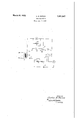
- FIG. 1 represents the primary of a transformer 2 which is used to couple my device to the apparatus in which are" flowing the currents whose eflects it is desired to measure.
- One terminal 3 of the secondary of the transformer 2 is connected to the filament 5 of a thermionic rectifier 6 through a resistance 7.
- the heating current fort e filament of the thermionic rectifier Gis supplied from a source of direct current power 8 through a rheostat 9 and the resistance 7.
- a milliammeter A is provided in series in this circuit for the determination of the correct current to be supplied to the filament of the thermionic rectifier 6.
- the other terminal 10 ofthe secondary 4 of the transformer 2 is connected to one terminal of a galvanometer G, the other terminal of which is connected through a switch 11 to the anode 12 of the thermionic rectifier 6.
- I have provided a variable resistance 13 to shunt a portion of the current flowing in the anode circuit of the thermionic rectifier around the galvanometer in case the current to be measured is higher than the limit to which the galvanometer G will read.
- the resistance 7 provides a sufiicient negative bias to revent any deflection of the galvanometer when no current is flowing in the primary 1 of the transformer 2.
- I have provided a'circuit in which the current may be measured by charging a condenser in the anode circuit of the rectifier and then discharging the condenser through the galvanometer G.
- This circuit consists of a connection from theterminal 10 of the secondary 4 of the transformer 2 to one terminal of a condenser 7 14, the other terminal of which is connected to a double-throw switch 15.
- One terminal 16 of the switch 15 is connected to the anode 12 of the thermionic rectifier 6.
- the other terminal 17 of the switch 15 is connected to 7 the galvanometer G.
- the operation of the device is as follows.-
- the terminals 18 and 19 of the primary 1 of the transformer 2 are either connecteddirectly to the circuit in which the alternating 30 current that it is desired to measure-is flowing or in parallel with a known resistance in 3 series with that circuit.
- the switch 15 is open and the switch 11 is closed.
- the filament 5 of the thermionic rectifier 6 is 85.
- the galvano'meter G gives a value that is proportionate to the amount of current flowing in the circuit under test. Should the current in the circuit under test he erratic the switch 11 is opened and the lever 20 of the switch 15 is pressed against the contact. 16
- thermionic rectifier 6 may be replaced by any rectifier which is sensitive enough to rectify weak currents.
- I have used a lurality of three element vacuum tubes suc as have been used in radio apparatus, with the grid shorted to the plate with very ood success.
- liquid rectifiers, if sta 1e, serve thepurpose equally as well.
- a rectifier means for coupling the rectifier to the source of alternating current
- a galvanometer in series with the rectifier
- a switch in series with the galvanometer and the rectifier
- a condenser in parallel with the galvanomet'er and a double pole switch, one pole of which is in series with the condenser and the rectifier and the other 01 of'hih" 'th-thcnd er.
- p e w c 1s m Senes W1 8 0 ens combination ofa rectlfier, means for coupling and the galvanometer.
- a therm1onic rectifier In an alternating current meter, the combination of a therm1onic rectifier, a source of ower therefor, a variable resistance and a ed resistance in series with the said source and the filament of the thermionic rectifier, a filament anode circuit for thereotifier, said filament anode circuit including the said fixed resistance, means'for coupling the rectifier to the source of alternating current to be measured, a measuring dev1ce,a condenser and means for alternately placing the condenser in series. with the coupling means and the rectifier andin parallel with the measuring device.
- a thermionic rectifier a source of power therefor, a variable resistance and a fixed resistance in series with the said source and the filament of the thermionic rectifier, a filament anode circuit for the rectifier, said filament anode circuit includthe measuring device in series with the rectifier and the coupling means.
- a thermionic rectifier a source of power therefor, a variable resist ance and a fixed resistance in series with the source of power and the filament of the ther mionic rectifier, and a filament anode circuit for the rectifier
- said filament-anode circuit including a transformer, the secofidary of which is connected in series with the fixed resistance and a measuring device and a condenser, means for alternately placing the condenser in series with the anode of the thermionic rectifier and the secondary of the transformer and in parallel with the measuring device and means for placing the measuring device, in series with the rectifier and the secondary of the'transformer.
- the rectifier to a source of alternating current, a condenser and a galvanometer, and means adapted to connect the condenser in series with the rectifier to charge said condenser and said means being also adapted to connect said condenser in series with said galvanometer to discharge said condenser through said galvanometer, whereb an indication of the maximum value of t e alternating current in said source may be obtained.
Landscapes
- Engineering & Computer Science (AREA)
- Power Engineering (AREA)
- Physics & Mathematics (AREA)
- General Physics & Mathematics (AREA)
- Measurement Of Resistance Or Impedance (AREA)
Description
IGNITION METER Filed Dec. 3. 1927 IN V EN TOR.
A TTORNEYS.
c. B. MIRICK v 1,851,947-
Patented Mar. 29, 1932 UNITED STATES PATENT OFFICE CARLOS 1B; MIBICK, 011 WASHINGTON, DISTRICT OF COLUMBIA, ASSIGNOR TO NATIONAL ELECTRICAL SUPPLY COMPANY, OF WASHINGTON, DISTRICT OF COLUMBIA, A'COBr POBATION OF VIRGINIA IGNITION METER Application filed December 3, 1927. Serial No. 237,579.
(GRANTED BINDER THE ACT OF MARCH 3, 1888, AS AMENDED APBIL 30, 1828; 370 0. G. 757) My invention relates broadly to apparatus for measuring the eflects of weak and erratic alternating currents and more particularly to apparatus for the galvanometric measurement of the maximum intensity of varlable currents. The object of my invention is to produce an apparatus which may be utilized to measure the effects of alternating currents that are weak or erratic such as the currents employed in the ignition systems of internal combustion engines or those alternating currents produced in radio apparatus by static or strays.
Further objects of my invention will ap pear more fully hereinatter as the descrlption of the method and apparatus is developed.
My invention consists substantially in the construction, combination and arrangement of parts associated therewith or as will be more fully hereinafter set forth as shown by the accompanying drawing and finally polnted out in the appended claims. I
Reference'is' to be had to the accompanying drawingforming a art of this specification in which the figure 1s a diagrammatic arrangement of the electrical apparatus embodying my invention. V
' Referring to the drawing numeral 1 represents the primary of a transformer 2 which is used to couple my device to the apparatus in which are" flowing the currents whose eflects it is desired to measure. One terminal 3 of the secondary of the transformer 2 is connected to the filament 5 of a thermionic rectifier 6 through a resistance 7. The heating current fort e filament of the thermionic rectifier Gis supplied from a source of direct current power 8 through a rheostat 9 and the resistance 7. A milliammeter A is provided in series in this circuit for the determination of the correct current to be supplied to the filament of the thermionic rectifier 6.
The other terminal 10 ofthe secondary 4 of the transformer 2 is connected to one terminal of a galvanometer G, the other terminal of which is connected through a switch 11 to the anode 12 of the thermionic rectifier 6. In parallel with the galvanometer G, I have provided a variable resistance 13 to shunt a portion of the current flowing in the anode circuit of the thermionic rectifier around the galvanometer in case the current to be measured is higher than the limit to which the galvanometer G will read. The resistance 7 provides a sufiicient negative bias to revent any deflection of the galvanometer when no current is flowing in the primary 1 of the transformer 2.
In addition totheabove described circuit, in which there is a direct reading of the current flowing in the anode circuit of the thermionic rectifier, I have provided a'circuit in which the current may be measured by charging a condenser in the anode circuit of the rectifier and then discharging the condenser through the galvanometer G.
This circuit consists of a connection from theterminal 10 of the secondary 4 of the transformer 2 to one terminal of a condenser 7 14, the other terminal of which is connected to a double-throw switch 15. One terminal 16 of the switch 15 is connected to the anode 12 of the thermionic rectifier 6. The other terminal 17 of the switch 15 is connected to 7 the galvanometer G.
The operation of the device is as follows.- The terminals 18 and 19 of the primary 1 of the transformer 2 are either connecteddirectly to the circuit in which the alternating 30 current that it is desired to measure-is flowing or in parallel with a known resistance in 3 series with that circuit. The switch 15 is open and the switch 11 is closed. When the filament 5 of the thermionic rectifier 6 is 85.
heated to the proper temperature as indicated y the milliammeter A the deflection shown the galvano'meter G gives a value that is proportionate to the amount of current flowing in the circuit under test. Should the current in the circuit under test he erratic the switch 11 is opened and the lever 20 of the switch 15 is pressed against the contact. 16
and held in this position for a suitable period oftimeQduring which the effect of the applied voltage is integrated. The lever 20 is then shifted to the contact 17 andthe deflection of the galvanometer G is noted. By the comparison of this deflection with the calibration curve of thegalvanometer G the said integrated efiect may bemeasured.
It is to be understood that the thermionic rectifier 6 may be replaced by any rectifier which is sensitive enough to rectify weak currents.- I have used a lurality of three element vacuum tubes suc as have been used in radio apparatus, with the grid shorted to the plate with very ood success. Further, liquid rectifiers, if sta 1e, serve thepurpose equally as well.
It will be understood that the above description and accompanying drawing comprehends only the general and preferred embodiment of my invention and that minor detail changes in the construction and arrangement of parts may be made within the scope of the appended claims without sacrificing any of the advantages of my invention.
The invention herein described may be manufactured and used by or for the Government of the United States for governmental purposes without -the payment to me of any royalty thereon or therefor.
What I claim is as follows:
1. In an alternating current meter, the combination of a rectifier, means for coupling the rectifier to the source of alternating current, a galvanometer in series with the rectifier a switch in series with the galvanometer and the rectifier, a condenser in parallel with the galvanomet'er and a double pole switch, one pole of which is in series with the condenser and the rectifier and the other 01 of'hih" 'th-thcnd er. p e w c 1s m Senes W1 8 0 ens combination ofa rectlfier, means for coupling and the galvanometer. p
2. In an alternating current meter, the combination of a therm1onic rectifier, a source of ower therefor, a variable resistance and a ed resistance in series with the said source and the filament of the thermionic rectifier, a filament anode circuit for thereotifier, said filament anode circuit including the said fixed resistance, means'for coupling the rectifier to the source of alternating current to be measured, a measuring dev1ce,a condenser and means for alternately placing the condenser in series. with the coupling means and the rectifier andin parallel with the measuring device.
3. In an alternating current meter, the:
combination of a thermionic rectifier, a source of power therefor, a variable resistance and a fixed resistance in series with the said source and the filament of the thermionic rectifier, a filament anode circuit for the rectifier, said filament anode circuit includthe measuring device in series with the rectifier and the coupling means.
4. In an alternating current meter, the
combination of a thermionic rectifier, a
' denser, and means for alternatel placing the condenser in series with the ano e of the thermionic rectifier and the secondary of the transformer and in parallel with the measuring device.
5. In an alternating current meter, the combination of a thermionic rectifier, a source of power therefor, a variable resist ance and a fixed resistance in series with the source of power and the filament of the ther mionic rectifier, and a filament anode circuit for the rectifier, said filament-anode circuit including a transformer, the secofidary of which is connected in series with the fixed resistance and a measuring device and a condenser, means for alternately placing the condenser in series with the anode of the thermionic rectifier and the secondary of the transformer and in parallel with the measuring device and means for placing the measuring device, in series with the rectifier and the secondary of the'transformer.
6. In an alternating current meter, the
the rectifier to a source of alternating current, a condenser and a galvanometer, and means adapted to connect the condenser in series with the rectifier to charge said condenser and said means being also adapted to connect said condenser in series with said galvanometer to discharge said condenser through said galvanometer, whereb an indication of the maximum value of t e alternating current in said source may be obtained.
CARLOS B. MIRICK.
ing the said fixed resistance, means for coupling the rectifier to the source of alternating current to be measured, a measuring device, acondenser, means for alternately placing the condenser in series with the coupling means and the rectifier and in parallel with the measuring device, and means for placing
Priority Applications (1)
| Application Number | Priority Date | Filing Date | Title |
|---|---|---|---|
| US237579A US1851947A (en) | 1927-12-03 | 1927-12-03 | Ignition meter |
Applications Claiming Priority (1)
| Application Number | Priority Date | Filing Date | Title |
|---|---|---|---|
| US237579A US1851947A (en) | 1927-12-03 | 1927-12-03 | Ignition meter |
Publications (1)
| Publication Number | Publication Date |
|---|---|
| US1851947A true US1851947A (en) | 1932-03-29 |
Family
ID=22894320
Family Applications (1)
| Application Number | Title | Priority Date | Filing Date |
|---|---|---|---|
| US237579A Expired - Lifetime US1851947A (en) | 1927-12-03 | 1927-12-03 | Ignition meter |
Country Status (1)
| Country | Link |
|---|---|
| US (1) | US1851947A (en) |
Cited By (4)
| Publication number | Priority date | Publication date | Assignee | Title |
|---|---|---|---|---|
| US2416276A (en) * | 1944-07-13 | 1947-02-18 | Baldwin Locomotive Works | Instantaneous recorder |
| US2480063A (en) * | 1945-10-06 | 1949-08-23 | Mallory & Co Inc P R | Cell testing circuit |
| US2862177A (en) * | 1955-02-28 | 1958-11-25 | Yale W Titterington | Apparatus for measuring the charge on buried conductors |
| US3584294A (en) * | 1967-07-17 | 1971-06-08 | Fenwal Inc | A system for measuring low levels of electrical energy |
-
1927
- 1927-12-03 US US237579A patent/US1851947A/en not_active Expired - Lifetime
Cited By (4)
| Publication number | Priority date | Publication date | Assignee | Title |
|---|---|---|---|---|
| US2416276A (en) * | 1944-07-13 | 1947-02-18 | Baldwin Locomotive Works | Instantaneous recorder |
| US2480063A (en) * | 1945-10-06 | 1949-08-23 | Mallory & Co Inc P R | Cell testing circuit |
| US2862177A (en) * | 1955-02-28 | 1958-11-25 | Yale W Titterington | Apparatus for measuring the charge on buried conductors |
| US3584294A (en) * | 1967-07-17 | 1971-06-08 | Fenwal Inc | A system for measuring low levels of electrical energy |
Similar Documents
| Publication | Publication Date | Title |
|---|---|---|
| GB1469849A (en) | Electronic battery testing device | |
| US2399674A (en) | Alternating current power bridge | |
| US2079485A (en) | Protective arrangement for electrical instruments | |
| US2432390A (en) | Testing machine | |
| US1836934A (en) | Electrical meter | |
| US1851947A (en) | Ignition meter | |
| US2961606A (en) | Capacitor testing device | |
| US1966185A (en) | Apparatus for measuring electrical conductivity | |
| US2022790A (en) | Frequency indicating system | |
| US1983665A (en) | Electrical measuring instrument | |
| US2587697A (en) | Apparatus for testing amplifiers | |
| US2841765A (en) | Electric ohmmeter | |
| US1957454A (en) | Power output indicator for high frequency apparatus | |
| US2451613A (en) | Electrical conductivity testing machine | |
| US2510691A (en) | Megohmmeter | |
| US2152690A (en) | Magnetic testing | |
| US2762976A (en) | Electrical measuring instrument | |
| US2466746A (en) | Means for measuring resistance at high voltage | |
| US2392737A (en) | Battery capacity tester | |
| US1715446A (en) | Electrical measuring apparatus | |
| US3476914A (en) | Temperature control arrangement | |
| US1931460A (en) | System of measuring capacity and power factor, and apparatus therefor | |
| USRE15469E (en) | Thermionic voltmeter | |
| US2937334A (en) | Heat transfer testing apparatus | |
| US2521917A (en) | Micrometer |