US1851946A - Wiper ring for reciprocating rods - Google Patents
Wiper ring for reciprocating rods Download PDFInfo
- Publication number
- US1851946A US1851946A US339524A US33952429A US1851946A US 1851946 A US1851946 A US 1851946A US 339524 A US339524 A US 339524A US 33952429 A US33952429 A US 33952429A US 1851946 A US1851946 A US 1851946A
- Authority
- US
- United States
- Prior art keywords
- ring
- rings
- rod
- segments
- wiper
- Prior art date
- Legal status (The legal status is an assumption and is not a legal conclusion. Google has not performed a legal analysis and makes no representation as to the accuracy of the status listed.)
- Expired - Lifetime
Links
- 239000007788 liquid Substances 0.000 description 3
- 238000012856 packing Methods 0.000 description 3
- 238000010276 construction Methods 0.000 description 2
- 230000006835 compression Effects 0.000 description 1
- 238000007906 compression Methods 0.000 description 1
- 210000004907 gland Anatomy 0.000 description 1
- 230000000717 retained effect Effects 0.000 description 1
Images

Classifications
-
- F—MECHANICAL ENGINEERING; LIGHTING; HEATING; WEAPONS; BLASTING
- F16—ENGINEERING ELEMENTS AND UNITS; GENERAL MEASURES FOR PRODUCING AND MAINTAINING EFFECTIVE FUNCTIONING OF MACHINES OR INSTALLATIONS; THERMAL INSULATION IN GENERAL
- F16J—PISTONS; CYLINDERS; SEALINGS
- F16J15/00—Sealings
- F16J15/16—Sealings between relatively-moving surfaces
- F16J15/26—Sealings between relatively-moving surfaces with stuffing-boxes for rigid sealing rings
- F16J15/28—Sealings between relatively-moving surfaces with stuffing-boxes for rigid sealing rings with sealing rings made of metal
Definitions
- This invention relates to improvements in rod packings and particularly to improvements in wiper rings for reciprocating rods.
- the object of my invention is to provide a wiper ring assembly for reciprocating rods which may be used in the ordinary stufiing box without altering the same.
- a further object is to provide a wiper ring assembly which will float freely in the stuiling box and always maintain a close lit on the piston rod even though it may have some lateral movement as it reciprocates.
- a still further object is to provide the rings with cooperating parts so that the joints of the rings will n-ever come into alignment.
- Fig. 1 is a side elevation of the wiper assembly in a is interposed between the rings.
- the wiper ring assembly which in the form illustrated in the drawings consists of three rings 20; 21 and 22.
- the ring 20 is comprised of three similar segments 24 which are retained in assembled relation by a garter spring 25 which lits in a groove 26 in the outer periphery of each of the segments.
- Each segment 24 includes lug portions 28 which project axially from the opposite side faces of the body of the segments. These lug portions are about half as long as the segment itself and are located midway between its ends.
- each segment 1s also provided on one side with a knife edged lip 32 which extends axially from the inner pe riphery thereof and which is adapted to fit closely about the piston rod 11 and as the piston rod reciprocates deiiect the oil it scrapes from the rod outwardly away from it.
- the center ring 21 is substantially identical in construction with the ring 20, being made in three segmentswith lugs 28 and oil delecting'lip 32. In this center ring 21, however, sockets 30 are provided in the. lugs 27 and 28 for the reception of compression springs 31.
- Ring 22 is constructed of three segments which are similar to the segments 24 of ring 20 having a lug portion 28 and knife edged oil deflecting lip portion 32v onl one side. The opposite side face of the segments are plain so that a relatively tight joint may be eifectedbetween this outer ring and the stuing box.
- the springs 31 are each provided with one end coil 33 materially greater in diameter than the rest of the spring. This end coil 33 its tightly in the sockets 30 of the center ring and retains the spring therein while the spring itself is free to operate inthe'socket.
- sockets 30 are located. to Vone side of the center of the lugs 28 to avoid having the spring come directly over the joints of the next adjacent ring segments against which the springs press.
- the rings may be 5 a provided with lips 32 on both sides and the liquids stripped from the -rod be drained to any desi-red place from the box 12.
- this wiper ⁇ ring assembly may be used on a horizontally as well as a vertically disposed piston rod, the views on the drawings being merely illustrativeand not limiting.
- each ring is in three sections, it is to be understood that the rings may be made in only two or more than three sections Constructed in the same general manner with substantially centrally disposed lugs and the adjacent rings interlocking as described above.
- the lips 32 of the rings would function in the same manner.
- a packing for a piston rod or the'like comprising a plurality of ring members each composed of a plurality of separate segments
- each segment of each ring having a knife edged oil deflecting lip fitting closely against said rod, all said lips extending in the same direction.
- AV packing for a piston rod or the like comprising a plurality of ring members each composed of a plurality of separate segments, means for holding said segments in contact with said rod, adjacent rings being notched and nteritting with each other, and resilient means carried by one of said rings tending to separate them in a direction longitudinal to said rod, each segment of each ring having a knife edged oil deflecting lip itting closely against said rod, all said lips extending in the same direction, there being in all positions of said rings a space adjacent each knife edge into which oil may flow.
Landscapes
- Engineering & Computer Science (AREA)
- General Engineering & Computer Science (AREA)
- Mechanical Engineering (AREA)
- Sealing Devices (AREA)
Description
March 29, 1932. A. H. KRUGMAN 1,851,946
WIPER RING FOR RECIPROCATING RODS Filed'feb. 1:5. 1929 z sheets-sheet 2 Patented Mar. 29, 1932 UNITEDL STATES PATENT yoFFicl:
ARNOLD H. KRUGMAN, OF ELYRIA, OHIO, ASSIGNOR TO ROMEO PUMP COMPANY, OF
i ELYRIA, OHIO, A CORPORATION OF OHIO WIPER RING FOR RIFJCIPROCATING-A RODS Application led February 13, 1929. Serial No. 339,524.
This invention relates to improvements in rod packings and particularly to improvements in wiper rings for reciprocating rods.
The object of my invention is to provide a wiper ring assembly for reciprocating rods which may be used in the ordinary stufiing box without altering the same.
A further object is to provide a wiper ring assembly which will float freely in the stuiling box and always maintain a close lit on the piston rod even though it may have some lateral movement as it reciprocates.
A still further object is to provide the rings with cooperating parts so that the joints of the rings will n-ever come into alignment.
With these and such other objects in view as will appear from the description the invention resides in all the novel features of construction and combination of parts here-` inafter described and particularly pointed out in the appended claims.
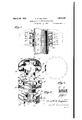
In the accompanying drawings, Fig. 1 is a side elevation of the wiper assembly in a is interposed between the rings.
Describing the invention as it is illustrated 1n the drawings and referring to the various parts by reference numerals, with like numerals referring to like parts in the several views, designates the top portion of a crank case through whichthe piston rod 11 reciprocates and which is provided with the usual stuiiing box 12 over which the gland or cover plate 13 is secured by bolts 14 with nuts 15 threaded thereon. A sheet gasket 16 is interposed between the plate 13 and casing 10 and the plate 13 is provided with openings 17 through which the oil may drain back into the crank case of the machine.
Within the stuffing box 12 iittingclosely about the rod 1l is the wiper ring assembly which in the form illustrated in the drawings consists of three rings 20; 21 and 22.
n The ring 20 is comprised of three similar segments 24 which are retained in assembled relation by a garter spring 25 which lits in a groove 26 in the outer periphery of each of the segments. Each segment 24 includes lug portions 28 which project axially from the opposite side faces of the body of the segments. These lug portions are about half as long as the segment itself and are located midway between its ends. It will be noted that these lugs do not extend the full width of the segment but are spaced outwardly from its inner periphery.A Each segment 1s also provided on one side with a knife edged lip 32 which extends axially from the inner pe riphery thereof and which is adapted to fit closely about the piston rod 11 and as the piston rod reciprocates deiiect the oil it scrapes from the rod outwardly away from it.
The center ring 21 is substantially identical in construction with the ring 20, being made in three segmentswith lugs 28 and oil delecting'lip 32. In this center ring 21, however, sockets 30 are provided in the. lugs 27 and 28 for the reception of compression springs 31.
The springs 31 are each provided with one end coil 33 materially greater in diameter than the rest of the spring. This end coil 33 its tightly in the sockets 30 of the center ring and retains the spring therein while the spring itself is free to operate inthe'socket.
Vhen the rings 2O, V 21 and 22 are assembled the lugs 28 interfit with each other so that there can be no relative rotation of the rings and it is impossible for the joints between the segments of one ring ever working into alignment with the joints of the next ring. When the rings are assembled about the rod 11 there lll gli
used.
The assembling of the rings on the rod -is obvious. The springs 81 held in the sockets 30 by the enlarged coil 33 prevent them from dropping out while being assembled.
It will be noted that the sockets 30 are located. to Vone side of the center of the lugs 28 to avoid having the spring come directly over the joints of the next adjacent ring segments against which the springs press.
rlhe operation of the wiper assembly is clear. As the rod 11 reciprocates carrying oil upward yat each upward stroke the lips 32 scrape off this oil delecting it outward between the rings to the outer parts of the stuffing box. 11 from where it drains through the openings 17 back into the ,crank case.
It is obvious that when the piston rod is reciprocating through a wall on each side of which are different liquids a second set of K, rings arranged with the lips 32 in the opposite direction may be used. They would prevent the liquid from being carried into the box 12.
It is also apparent that the rings may be 5 a provided with lips 32 on both sides and the liquids stripped from the -rod be drained to any desi-red place from the box 12.
It is also obvious that this wiper `ring assembly may be used on a horizontally as well as a vertically disposed piston rod, the views on the drawings being merely illustrativeand not limiting.
lhile I have illustrated each ring as being in three sections, it is to be understood that the rings may be made in only two or more than three sections Constructed in the same general manner with substantially centrally disposed lugs and the adjacent rings interlocking as described above. The lips 32 of the rings would function in the same manner.
Having thus described my invention, what I claim is 1. A packing for a piston rod or the'like comprising a plurality of ring members each composed of a plurality of separate segments,
means for holding said segments in contact with said rod, adjacent rings being notched and interfitting with each other, and resilient means carried by one of said rings tending to separate them in a directionV longitudinal to said rod, each segment of each ring having a knife edged oil deflecting lip fitting closely against said rod, all said lips extending in the same direction. n
2; AV packing for a piston rod or the like comprising a plurality of ring members each composed of a plurality of separate segments, means for holding said segments in contact with said rod, adjacent rings being notched and nteritting with each other, and resilient means carried by one of said rings tending to separate them in a direction longitudinal to said rod, each segment of each ring having a knife edged oil deflecting lip itting closely against said rod, all said lips extending in the same direction, there being in all positions of said rings a space adjacent each knife edge into which oil may flow.
In testimony whereof, I hereunto affix my signature.
ARNOLD H. KRUGMAN.
Priority Applications (1)
| Application Number | Priority Date | Filing Date | Title |
|---|---|---|---|
| US339524A US1851946A (en) | 1929-02-13 | 1929-02-13 | Wiper ring for reciprocating rods |
Applications Claiming Priority (1)
| Application Number | Priority Date | Filing Date | Title |
|---|---|---|---|
| US339524A US1851946A (en) | 1929-02-13 | 1929-02-13 | Wiper ring for reciprocating rods |
Publications (1)
| Publication Number | Publication Date |
|---|---|
| US1851946A true US1851946A (en) | 1932-03-29 |
Family
ID=23329408
Family Applications (1)
| Application Number | Title | Priority Date | Filing Date |
|---|---|---|---|
| US339524A Expired - Lifetime US1851946A (en) | 1929-02-13 | 1929-02-13 | Wiper ring for reciprocating rods |
Country Status (1)
| Country | Link |
|---|---|
| US (1) | US1851946A (en) |
Cited By (1)
| Publication number | Priority date | Publication date | Assignee | Title |
|---|---|---|---|---|
| US5913812A (en) * | 1995-06-07 | 1999-06-22 | Electric Boat Corporation | Steam seal air removal system |
-
1929
- 1929-02-13 US US339524A patent/US1851946A/en not_active Expired - Lifetime
Cited By (2)
| Publication number | Priority date | Publication date | Assignee | Title |
|---|---|---|---|---|
| US5913812A (en) * | 1995-06-07 | 1999-06-22 | Electric Boat Corporation | Steam seal air removal system |
| US5941506A (en) * | 1995-06-07 | 1999-08-24 | Electric Boat Corporation | Steam seal air removal system |
Similar Documents
| Publication | Publication Date | Title |
|---|---|---|
| US2180795A (en) | Packing | |
| US9803752B2 (en) | Seal assembly | |
| US2210823A (en) | Laterally expanded oil seal | |
| US3084946A (en) | Reciprocating rod packing | |
| US1828178A (en) | Piston rod packing and scraping device | |
| CN205371632U (en) | Cambered surface Y composite seal that appears | |
| US2267183A (en) | Stuffing box | |
| US1851946A (en) | Wiper ring for reciprocating rods | |
| US1822521A (en) | Piston rod packing and scraping means | |
| US2367403A (en) | Fluid seal | |
| US2266935A (en) | Stuffing box | |
| US2006602A (en) | Packing | |
| US3068017A (en) | High pressure packing adaptor | |
| US996446A (en) | Rod-packing. | |
| US1928122A (en) | Flexible stuffing box assembly | |
| US2041316A (en) | Flexible stuffing box assembly | |
| US3330569A (en) | Packing cone with doubly curved surfaces | |
| US1617952A (en) | Rod packing | |
| US1788966A (en) | Automatically-adjustable seal packing | |
| US4192517A (en) | Anti-scale stuffing box improvement | |
| US1326242A (en) | Rod and shaft packing | |
| US2243598A (en) | Wellhead fitting | |
| US557107A (en) | Louie henry clark | |
| US2526590A (en) | Shaft seal | |
| US1881555A (en) | Oil saver |