US1851945A - Apparatus for expressing bakers' material - Google Patents
Apparatus for expressing bakers' material Download PDFInfo
- Publication number
- US1851945A US1851945A US357301A US35730129A US1851945A US 1851945 A US1851945 A US 1851945A US 357301 A US357301 A US 357301A US 35730129 A US35730129 A US 35730129A US 1851945 A US1851945 A US 1851945A
- Authority
- US
- United States
- Prior art keywords
- roller
- container
- chamber
- rollers
- openings
- Prior art date
- Legal status (The legal status is an assumption and is not a legal conclusion. Google has not performed a legal analysis and makes no representation as to the accuracy of the status listed.)
- Expired - Lifetime
Links
- 239000000463 material Substances 0.000 title description 69
- 238000007493 shaping process Methods 0.000 description 7
- 238000005520 cutting process Methods 0.000 description 6
- 238000010276 construction Methods 0.000 description 4
- 238000000034 method Methods 0.000 description 4
- 235000014594 pastries Nutrition 0.000 description 3
- 238000003825 pressing Methods 0.000 description 3
- 235000015895 biscuits Nutrition 0.000 description 2
- 230000001276 controlling effect Effects 0.000 description 2
- 238000004519 manufacturing process Methods 0.000 description 2
- 239000002184 metal Substances 0.000 description 2
- 230000010355 oscillation Effects 0.000 description 2
- 240000004808 Saccharomyces cerevisiae Species 0.000 description 1
- 244000299461 Theobroma cacao Species 0.000 description 1
- 235000019219 chocolate Nutrition 0.000 description 1
- 238000004140 cleaning Methods 0.000 description 1
- 230000001427 coherent effect Effects 0.000 description 1
- 238000004891 communication Methods 0.000 description 1
- 235000009508 confectionery Nutrition 0.000 description 1
- 230000000694 effects Effects 0.000 description 1
- 238000003780 insertion Methods 0.000 description 1
- 230000037431 insertion Effects 0.000 description 1
- 235000011837 pasties Nutrition 0.000 description 1
- 229920000136 polysorbate Polymers 0.000 description 1
- 230000001105 regulatory effect Effects 0.000 description 1
- 238000005096 rolling process Methods 0.000 description 1
- 238000000926 separation method Methods 0.000 description 1
- 239000007779 soft material Substances 0.000 description 1
Images


Classifications
-
- A—HUMAN NECESSITIES
- A21—BAKING; EDIBLE DOUGHS
- A21C—MACHINES OR EQUIPMENT FOR MAKING OR PROCESSING DOUGHS; HANDLING BAKED ARTICLES MADE FROM DOUGH
- A21C11/00—Other machines for forming the dough into its final shape before cooking or baking
- A21C11/16—Extruding machines
Definitions
- This invention relates to a process of and apparatus for expressing quantities of bakers material of the consistency for instance of icing, dough or pasty material.
- the invention consists in the material being conveyed from the material container by means of smooth rollers rotating in opposite directions into a relatively small discharge chamber, the rollers controlling communication ben tween the chamber and the container.
- the material is then forced, substantially in the same direction of movement as at the intro duction into the chamber, through the chamber to outlet openings from which it is expressed and at the same time shaped, so that the nature or quality of the materials to be treated is unfavourably aflected to the least possible extent.
- the invention is based on the discovery that the best method of supplying the material to be treated to the expression chamber is by means of feedrollers, as this ensures that the material passing into the chamber has a uniform density throughout the whole width of the chamber. This cannot be ensured by the use of other means for the transfer of the material from the container to the chamber, for instance, by the use of suction pistons or plungers.
- soft, frothy, or similar materials such as sillabubs, sweets, pastry, biscuits, macaroons or chocolates may be made into small articles of a given size and of the most varied shapes.
- the machine also substantially facilitates the introduction of the material into the expressing chamber, as the space which becomes openings, and a very large part of the boundary surfaces of the expression chamber is ,formed by the circumferential surfaces of the rollers, and in that way the surfaces exerting friction on the material are considerably reduced.
- this plate may also be given, for the purpose of shaping the material, any imaginable movement in the horizontal plane with a considerably greater facility than in other machines.
- This makes it possible to manufacture drop-shaped portions when the outlet openings (also called nozzles) are standing still during the shaping, and also portions which are shaped by the movement of the nozzles.
- cam discs are preferably used.
- the portions of paste or dough may be made from different materials, for instance the so-called filled confectioners work. This may be done by extruding an ornamentation or a second layer of a material of-a different kind on semi manufactured articles positioned by the table conveying devicesunder the expression nozzles, or by arrangin behind one another several-upper parts w ich put on materials of different kinds.
- An advantage of the machine is also that the upper partsima be directly turned apart for the purpose 0 cleaning the expression chamber. l
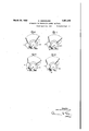
- Figures 2 and 3 show the positionof the container and of the expressing device at the beginning and at the end of the feeding-in.
- Figure 4 shows the cam gear for the driving of the nozzles.
- FIG. 5 shows a cam disc with two guides.
- Figures 6 to 9 show the position of the rollers during the feeding-in .a'nd' fthe express ng. a
- Fig. 11 is an end view'of the same.
- Fig. 12 is a detailed side elevation of the mounting and-the actuating means of the second roller.
- Fig. 13 is an end view of the same.
- Fig. .14 is a detailed side elevation of the cam shaft and of the actuating means for the cutting device.
- Fig. 15 is a detailed top planview of the shaft 52 and the members mounted thereon.
- v Fig. 16 is a side elevation of the cam shaft.
- 1 Fig. 17 is a detailed top planview of the camshaft.
- Figure 18 is a side elevation view ofthe machine showing an arrangement employing two containers and also showing the driving connections to a disc provided with cam grooves on both sides as in- Figure 5.
- Figure 19 is a plan view of the disc shown in Figures 5 and 18'disc1osing the connecting means for guiding the horizontal movement of the nozzle plate:
- the container 2- for the material to be treated.
- the container is closed at the bottom by two oppositely vrotating, practically smooth,
- rollers 3, 4 which are adaptedtorotate with thesame circumferential speed under the ac- 7 -tion of spur wheels.
- the larger-roller 3 is secured to "a spindle 5 to which is further secured a ratchet wheel 6.
- the pawls 7 for the said ratchet wheel 6 are rotatable on pins I 8 which are secured to a bell crank lever 9.
- the bell crank lever 9 is rotatable on the spindle 5 and connected by means of a pin 10 to a connecting rod llwhich engages by means of 'a pin 12 with a block 13.
- the block 13 is adjustable in a guide 14 by means of a spindle 15 andof a hand wheel 16, in order to enable the extent of rotation of the rollers 3, 4 to be adjusted.
- the guide 14 is rigidly securedto aspindle 17 which is rigidly secured to a furtherguide 18.
- In the uide 18 travels a block 19which is connected y a pin 20 to a connecting rod'21, the other 7.
- crank disc 23 is secured to the spindle 24 which is driven by means of a gearing 25, 26, 27, 28 by an electric motor 29.
- ad- 1 justable slideblock 30 on which is mounted the connecting rod 31 which is connected with its other end to the pin 32 mounted in the pivoted container 2.
- On the spind1e 24 is mounted a cam disc v 36 on which travels a roller 37 of a pressure rod 38.
- the pressure rod 38' engages with its other end formed into a guide track, under 1 a pin 39 of a lever 40 which is secured to a spindle 41.
- On the spindle"41. are mounted levers 42 which are connected to a bridge 43- in which aif'niounted gear Wheels 44 which effect. the c ection between the gear wheels 45 and 46 of the rollers 3 and 4. Owing to the movement of the parts 36 to 46, the roller 4 is lifted oflt from the roller 3 or again pressed against the same.
- v are used. These the cutting device of which is guided by an arm 59 in a guide 60. This guide is vertically reciprocated by a rod 61 with a roller 62 and a cam disc 63.
- a cross piece 65, a spring 66, a-pin 67, a hand wheel 68, a connecting pin 69 and a guide block 70 parts are connected by a pin 71 and a connecting rod 72 to a pressure roller 73 and are moved by a cam disc 74.
- Means are also provided for adjusting the height of the other end of the table.
- the portion 115 is raised or lowered by turning the screw 116.
- As the left end of the. conveyor is mounted on the portion 115 it is also raised or lowered by the screw 116.
- FIG 2 the upper part of the machine is shown separately.
- an insertion piece 75 under which is provided an adjustable nozzle plate 76 which is held and guided by the guides 77.
- the nozzle plate 76 are arranged interchangeable.nozzles or pipes 78 which are intended for the dressing portions as they are pressed out.
- the nozzle plate is driven in one direction for instance by means of three cam discs 79, 80, 81 arranged side by side, through the bell crank levers 82, 83 and connecting rod 84.
- the cam disc moves the nozzle plate 76 by means of a double armed lever 85 and of a connecting rod 86 in a direction at right angles to the first one.
- the nozzle plate makes any desired movement according to the construction of the cam discs.
- the nozzle plate should be driven by three cam discs. It is possible to use for instance only two cam discs, one of which brings about one par-t of the movement in one direction, whilst the other cam disc controls the movement at right' angles to it. In such a case, it is necessary to make the nozzle plate 7 6 with a parallel guide so as to prevent it from turning. But it is also possible to use one single cam disc 87 with two or more guides 88 ( Figure 5). In Figures 18 and 19 the use of a single cam disc 87 is shown. The disc is mounted horizontally on the vertical shaft 109 rotatably mounted adjacent the frame 1, the shaft 109 by any suitable connections such as by the belt and pulley arrangement shown in Figure 18.
- the connecting means between the cam disc 87 and the plate 76 are clearly shown in Figure 19.
- the cam grooves 88 in each side of the disc 87 are engaged by elements on the arms 110 and 111. These arms respectively connect with rods 112 and 113 connected to the plate 76. I
- the plate 76 is thus moved in a horizontal plane in all directions. The movement of the plate is directed bv the par ticular path of the cam grooves.
- the double armed arrangement indicated at 114 is to insure that any movement as the result of movement of the rod 112 will also be communicated to the other end, of the plate 76.
- roller 89 which is rotatably mounted in the ends of two arms 90, the other ends of the arms being pivoted at fixed points.
- the roller thus does not move with the container but rests by-its own weight on the material being fed to the rollers.
- This roller doesnot participate in the oscillating movements of the upper part, but'at each pressing out oscillation movement rolls the material in the container widely to the shape of a cake.
- this roller pushes the material into the inlet openings of the feed rollers.
- the direction of rotation of this roller is controlled by a spring wheel device 91 consisting of aratchet integral with the roller and a pawl spring pressed into engagement with the ratchet.
- rollers need not bebrought together so far that the material is completely divi (led and cut through.
- degree of bringing together of the rollers may be chosen differently-to suit the nature of the i materialitreated', provided only that the flowrubber-like extensibility,
- two or more upper parts may be arranged behind one anthe movement of which is derived from the first upper part by means of the connecting rods 93, 94, 95 as shown in Fig. 18.
- the table may also be pressed for an instant against -the nozzles and lowered again, at the beginning and at the end of the dressing.
- bridges may provided in the expressing opening.
- the material therefore comes out the cutting off by means of the cuttin wire, are pushed togather to a coherent body, the total shape of the body, if desired with openings and recesses in the interior of thebody, being preserved.
- the process may also be carried out by means of a machine in which one pivoted roller is placed, before the beginning of the expressing, against a fixed roller, and by the lifting of the table the parts of the expression chamber are pushed together in such a way that their space becomes smaller, and the re- .3 WhatIclaim1s:
- Apparatus for. forming objects of baks material comprisi ga pivotally mounted taine'r, a pair of rollers arranged in the er pofrtion of. saidcontainer to forma as i'swellknown has a it is sufficient to on the ers material comprising a chamber therebeneath, one of said rollers being rotatably mounted in the'container, the other roller being oscillatably mounted in said container an thereby adapted to swing vertically with the container and to move to,- wards and from said first roller, the chamber having openings in the bottom thereof, means for moving said second roller towards said first roller and for then swinging said container and second roller around said first roller to feed material to said chamber, then to isolate said chamber from the remainder of the container, hen to express material throu h said openings.
- Eppa'ratus for forming objects of bakers material comprising a pivotally mounted container, a pair of rollers arrangedin the lower portion of said container to form a chamber therebeneath, one of said rollers being rotatably mounted in the container, the
- rollers oscillatably mounted towards 'and from said first roller and to swing vertically with .the container, said chamber having openings in the bottom thereof, and means for moving said second roller towards said first roller and for then swinging said container and second roller around said first roller to first feed material to said chamber, then isolate said chamber from the remainder of the container, and then express the material in the chamber through said openings, and means for shaping the material as it is expressed.
- Apparatus for forming articles of bakpivotally mounted container a. pair of rollers arranged in the lower portion of said container to form a chamber therebeneath, one of said rollers being rotatably mounted in the container, the other roller being oscillatably mounted in the container for movement towards and from said first roller and for substantiallyvertical movement with said container, said chamber having openings in the bottomthereof, and means for movlng said second roller toward said first roller and for then swinging said container and second roller downward around material from said .lower portion of said container, one of said rollers being rotatably mounted in said container, a pair of pivoted arms mounted on said container, said second roller being rotatably mounted in said pivoted arms, said chamber having openings in the lower part thereof, and means for moving said secon roller toward said first roller and then downward with the container around said first roller.
- Apparatus for forming ers'material comprising a pivotally mounted articles of bak- I said container, a pair of arms pivotally mounted on said container, said second roller being rotatably mounted in said arms, a link connected to said arms adapted to move horibakers material comprising zontally to move said second roller towards and from said first roller, said chamber having openings in'the bottom thereof.
- Apparatus for forming articles of bakers material comprising a pivotally mounted container, a pair of rollers arranged in the lower portion of said container to form a chamber therebeneath, one of said rollers being rotatably. mounted in said container, the other. of said rollers being adapted to move towards and from said first roller and to oscillate with said container, and ascra-per mounted on said pivoted portion of the containerand adapted to contact with said second roller and to engage slidably Igvith the outer face of the wall of said cham- 7.
- Apparatus for forming articles of apivotally mounted container a pair of rollers arranged in the lower portion of said container to form a chamber therebeneath, one of said rollers being rotatably mounted in said container, a scraper on the pivoted portion of said container, a pair of arms pivoted on the ends of said scraper, said second roller being rotatably mounted in said arms, a link connected to said arms and adapted to be moved horizontally to move said second roller towards and from said first roller, said scraper contacting said second: roller and slidably engaging the outer face of the wall of said chamber, said chamber having openings in the bottom thereof.
- Apparatus for forming articles of bakers material comprising a container, a pair of rollers arranged in the lower portion of said container to form a chamber therebeneath, one of said rollers being rotatably mounted in the container, the other roller being adapted to be moved towards and from said first roller'and vertically, link means for moving said second roller and gearing between said rollers mounted on said link means and adapted to move with said second roller and to constantly engage said first roller so as to preserve a driving connection :axis as said container, a pair of arms pivoted on the pivoted container, the second roller being rotatably mounted in said arms, a link connected to said arms and adapted to be moved horizontally to move said second roller to'wards and from said first roller, and gearing between said rollers mounted on said link and adapted to maintain a driving connection between said rollers, said chamber having openings in the bottom thereof.
- Apparatus for forming articles of bakers material comprising a container, a pair of rollers arranged in the lower portion of said container to form a chamber therebcneath, means for operatingsaid rollers to isolate said chamber from the remainder of the container and to express material from said chamber, and a third roller oscillatably mounted above said first and second rollers and independent of said roller operating means and adapted to flatten material passing between said first and second rollers.
- Apparatus as claimed in claim 10 and a pawl and ratchet adapted to prevent rotation of said third roller in one direction during oscillation.
- Apparatus for forming objects of bakers material comprising a pivot-ally mounted container, a pair of rollers arranged in the lower portion of said container to form a chamber therebeneath, one of said rollers being rotatably mounted in the container, the other roller being oscillatably mounted in the container and thereby adapted to swing ver tically with the container and to move towards and from said first roller, means for moving said rollers to feed material to said chamber, to isolate said chamber from the remainder of the container, and to express material from said chamber, said chamber having openings in the bottom thereof, and means for moving said openings horizontally for shaping the material.
- a last mentioned means comprising a single cam disc having a plurality of curved guides thereon and members engaging said guides and connected to said openings.
- Apparatus as claimed in claim 1 and a second container similar in construction to said first container and arranged adjacent thereto, a conveying device passing between both said containers, whereby articles of two materials may be formed, and means connected to said first container for actuating said second container.
- Apparatus for forming articles of bakers material comprising a nozzle, means for extruding material through said nozzle,
- Apparatus for forming articles of bakers material comprising a nozzle, means for extruding material through said nozzle, an endless conveyor passing beneath said nozzle, a second nozzle in front of said first nozzle and above said endless conveyor, means for extruding material from said second nozzle, means for adjusting the height of either end of said conveyor, means for moving said conveyor upward against said nozzles, and means for moving said conveyor suddenly away from said nozzles.
- Apparatus for forming articles of bakers material comprising two containers, means connected to one of the containers for actuating the other container, a vconveyor passing beneath both said containers, means for expressing material from said containers, means-for raising one end of said conveyor, and means for adjusting said raising means to compensate for differences in the height of said containers.
- Apparatus for forming objects of bakers material comprising a pivotally mounted container, a pair of rollers arranged in the lower portion of said container to form a chamber therebeneath, one of said rollers being rotatably mounted in the container, the other roller being oscillatably mounted in the container and thereby adapted to swing vertically with the container and to move towards and from said first roller, means for moving said rollers to feed material to said chamber, to isolate. said chamber from the remainder of the container, and to express material from said chamber, said chamber having openings in the bottom thereof, and means for moving said openings horizontally for shaping the material, the total move- 7 ment imparted to the openings having a number of components, and individual cam grooves for controlling each component.
- Apparatus for forming articles of bakers material comprising an expressing chamber having openings therein, nozzles positioned adjacent said openings, the cross sections of said nozzles being less than the cross sections of said opemngs, means for expressing material through said openings and nozzles, and means for moving said nozzles to various points within the geometrical limits of said openings during the expressing action.
Landscapes
- Life Sciences & Earth Sciences (AREA)
- Engineering & Computer Science (AREA)
- Food Science & Technology (AREA)
- Confectionery (AREA)
Description
Mar'dl 1932- o. KREMMLING APPARATUS FOR nxrnnssme mums mam.
Filed April 22. 1929 5 Sheets-Sheet l March 29, 1932. KREMM N 1,851,945
APPARATUS FOR EXPRESSING BAKERS IATERIALY Filed April 22. 1929 6 Sheets-Sheet 2 7 In Venfor;
I (7% 11 rernmlvwy Q WQQL M 29, 1932- O. KREMMLING 1,851,945
- APPARATUS FOR EXPRESSING BAKERS TERIAL Filed April 22. 1929 5 sheets-sheet :5
arm lf/ZEMMLM/G March 29, 1932. o. KREMMLING I APPARATUS FOR EXPRESSING BAKERS" IATERIAIJ Filed April 22. 1929 a Sheets-Sheet 4 INVENTOR. 0770 KEEMMLI/VG March 29, 1932. Q-KRF MML-ING 1,851,945
I APPARATUS FOR EXPRESSING BAKERS MATEERIAL' T Filed A ril 22, 1929 5 Sheets-Sheet 5 $1 71! 7 gwvmtcw J afixremmzzivy Patented Mar. 29,1932
UNITED STATES OTTO KREMMLING, OF OSCHERSLEBEN, GERMANY APPARATUS FOR EXPRESSING BAKERS MATERIAL Apparatus filed April 22, 1929, Serial No.
This invention relates to a process of and apparatus for expressing quantities of bakers material of the consistency for instance of icing, dough or pasty material. The invention consists in the material being conveyed from the material container by means of smooth rollers rotating in opposite directions into a relatively small discharge chamber, the rollers controlling communication ben tween the chamber and the container. The material is then forced, substantially in the same direction of movement as at the intro duction into the chamber, through the chamber to outlet openings from which it is expressed and at the same time shaped, so that the nature or quality of the materials to be treated is unfavourably aflected to the least possible extent.
The invention is based on the discovery that the best method of supplying the material to be treated to the expression chamber is by means of feedrollers, as this ensures that the material passing into the chamber has a uniform density throughout the whole width of the chamber. This cannot be ensured by the use of other means for the transfer of the material from the container to the chamber, for instance, by the use of suction pistons or plungers.
In the hitherto known machines with feed rollers, the action of the rollers on the exceedingly soft material is so unfavourable that the nature or quality-of the said material is injuriously affected. Thus for instance the 115 material for biscuits becomes too tough for shaping, While frothy material becomes on the contrary, too sodden. In the case of materials rich in fat, a separation of the fat'takes place, causing a great reduction of the qual- 40 ity of the finished pastry, as well as an unintended reduction of size of the single pieces of pastry. This is particularly true in hot seasons, but is also true at other times, for in the industries concerned high temperatures are generally used.
357,301, and in Germany June 16, 1926.
- With the machine intended for carrying out the process according to this invention, soft, frothy, or similar materials such as sillabubs, sweets, pastry, biscuits, macaroons or chocolates may be made into small articles of a given size and of the most varied shapes. The machine also substantially facilitates the introduction of the material into the expressing chamber, as the space which becomes openings, and a very large part of the boundary surfaces of the expression chamber is ,formed by the circumferential surfaces of the rollers, and in that way the surfaces exerting friction on the material are considerably reduced.
Owing to thefixed mounting of the plate containing the outlet openings, this plate may also be given, for the purpose of shaping the material, any imaginable movement in the horizontal plane with a considerably greater facility than in other machines. This makes it possible to manufacture drop-shaped portions when the outlet openings (also called nozzles) are standing still during the shaping, and also portions which are shaped by the movement of the nozzles. For bringing about these movements cam discs are preferably used.
It is possible moreover that the portions of paste or dough may be made from different materials, for instance the so-called filled confectioners work. This may be done by extruding an ornamentation or a second layer of a material of-a different kind on semi manufactured articles positioned by the table conveying devicesunder the expression nozzles, or by arrangin behind one another several-upper parts w ich put on materials of different kinds. I
Owing to the arrangement of edge discs on one of the rollers, for instance on the fixed one, it has also become possible to feed-in the material in-a uniform manner into the expressioir chamber for the purpose of obtainingpieces of the same size. This is further greatly facilitated by the roller pivotally mounted in the container, first rolling the material wide, during the pressing out movement, and
theupushing it during the feeding in movement into the feeding-1n opening.
An advantage of the machine is also that the upper partsima be directly turned apart for the purpose 0 cleaning the expression chamber. l
By way of example, two constructions of the machine according to the invention are diagrammatically illustrated in the accompanying drawings. 1 v 1 y Figure 1 shows the machine in side elevation.
Figures 2 and 3 show the positionof the container and of the expressing device at the beginning and at the end of the feeding-in. Figure 4 shows the cam gear for the driving of the nozzles. i
I Figure 5 shows a cam disc with two guides. Figures 6 to 9 show the position of the rollers during the feeding-in .a'nd' fthe express ng. a
- Figs 10is adetailed side elevation of the pawl and ratchet drive for the rollers.
Fig. 11 is an end view'of the same.
Fig. 12 is a detailed side elevation of the mounting and-the actuating means of the second roller.
Fig. 13 is an end view of the same.
Fig. .14 is a detailed side elevation of the cam shaft and of the actuating means for the cutting device.
Fig. 15 is a detailed top planview of the shaft 52 and the members mounted thereon. v Fig. 16 is a side elevation of the cam shaft. 1 Fig. 17 is a detailed top planview of the camshaft. a
Figure 18 is a side elevation view ofthe machine showing an arrangement employing two containers and also showing the driving connections to a disc provided with cam grooves on both sides as in- Figure 5.
. Figure 19 is a plan view of the disc shown in Figures 5 and 18'disc1osing the connecting means for guiding the horizontal movement of the nozzle plate:
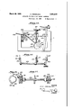
On the machine frame 1 is mounted the container 2- for the material to be treated.
-. The container is closed at the bottom by two oppositely vrotating, practically smooth,
The block 13 is adjustable in a guide 14 by means of a spindle 15 andof a hand wheel 16, in order to enable the extent of rotation of the rollers 3, 4 to be adjusted. The guide 14 is rigidly securedto aspindle 17 which is rigidly secured to a furtherguide 18. In the uide 18 travels a block 19which is connected y a pin 20 to a connecting rod'21, the other 7.
end of which is driven by the pin 22 of the adjustable crank disc 23. The crank disc 23 is secured to the spindle 24 which is driven by means of a gearing 25, 26, 27, 28 by an electric motor 29.
In the guide 18 there is also another ad- 1 justable slideblock 30 on which is mounted the connecting rod 31 which is connected with its other end to the pin 32 mounted in the pivoted container 2. The. container 2 with the roller 4 mounted in the same, and with a piston part or scraper 33 rigidly mounted means of the On the spind1e 24 is mounted a cam disc v 36 on which travels a roller 37 of a pressure rod 38., The pressure rod 38' engages with its other end formed into a guide track, under 1 a pin 39 of a lever 40 which is secured to a spindle 41. On the spindle"41. are mounted levers 42 which are connected to a bridge 43- in which aif'niounted gear Wheels 44 which effect. the c ection between the gear wheels 45 and 46 of the rollers 3 and 4. Owing to the movement of the parts 36 to 46, the roller 4 is lifted oflt from the roller 3 or again pressed against the same.
'On the spindle 24 is further mounted an adj ustable' crank disc 47 to the pin 48 of which is secured a connecting rod 49, they other end of which engages, with the pin 50 of a lever 51 which is rotatable on the spindle 52. In the rotatable or rocking-lever 51 is provided a guide 53 in which slides a block 54 which On the spindle 52 is mounted with a guide a further lever 56 whichimoves the connecting; rod 57 which engages 'with cutting arms 58,
- metal plates carrying the portions expressed.
v are used. These the cutting device of which is guided by an arm 59 in a guide 60. This guide is vertically reciprocated by a rod 61 with a roller 62 and a cam disc 63.
For raising and lowering table 64 a cross piece 65, a spring 66, a-pin 67, a hand wheel 68, a connecting pin 69 and a guide block 70 parts are connected by a pin 71 and a connecting rod 72 to a pressure roller 73 and are moved by a cam disc 74. Means are also provided for adjusting the height of the other end of the table. In Figures 1 and 18 the portion 115 is raised or lowered by turning the screw 116. As the left end of the. conveyor is mounted on the portion 115 it is also raised or lowered by the screw 116.
In Figure 2, the upper part of the machine is shown separately. Under the intermediate part 34 is arranged an insertion piece 75 under which is provided an adjustable nozzle plate 76 which is held and guided by the guides 77. In the nozzle plate 76 are arranged interchangeable.nozzles or pipes 78 which are intended for the dressing portions as they are pressed out. The nozzle plate is driven in one direction for instance by means of three cam discs 79, 80, 81 arranged side by side, through the bell crank levers 82, 83 and connecting rod 84. The cam disc moves the nozzle plate 76 by means of a double armed lever 85 and of a connecting rod 86 in a direction at right angles to the first one.
, Owing to the co-operation of these two moveis driven from the shaft 24 ments, the nozzle plate makes any desired movement according to the construction of the cam discs.
It is not absolutely essential that the nozzle plate should be driven by three cam discs. It is possible to use for instance only two cam discs, one of which brings about one par-t of the movement in one direction, whilst the other cam disc controls the movement at right' angles to it. In such a case, it is necessary to make the nozzle plate 7 6 with a parallel guide so as to prevent it from turning. But it is also possible to use one single cam disc 87 with two or more guides 88 (Figure 5). In Figures 18 and 19 the use of a single cam disc 87 is shown. The disc is mounted horizontally on the vertical shaft 109 rotatably mounted adjacent the frame 1, the shaft 109 by any suitable connections such as by the belt and pulley arrangement shown in Figure 18.
The connecting means between the cam disc 87 and the plate 76 are clearly shown in Figure 19. The cam grooves 88 in each side of the disc 87 are engaged by elements on the arms 110 and 111. These arms respectively connect with rods 112 and 113 connected to the plate 76. I The plate 76 is thus moved in a horizontal plane in all directions. The movement of the plate is directed bv the par ticular path of the cam grooves. The double armed arrangement indicated at 114 is to insure that any movement as the result of movement of the rod 112 will also be communicated to the other end, of the plate 76.
For the purpose of correctly feeding-in the material and of proper covering of the drawin'g-in point of the feed rollers for protecting the attendants, there is provided in the container a roller 89 which is rotatably mounted in the ends of two arms 90, the other ends of the arms being pivoted at fixed points. The roller thus does not move with the container but rests by-its own weight on the material being fed to the rollers. This roller doesnot participate in the oscillating movements of the upper part, but'at each pressing out oscillation movement rolls the material in the container widely to the shape of a cake. As soon however as the container is turned to the other side for the purpose of feeding-in, this roller pushes the material into the inlet openings of the feed rollers. The direction of rotation of this roller is controlled by a spring wheel device 91 consisting of aratchet integral with the roller and a pawl spring pressed into engagement with the ratchet. By this structure the roller may turn in only one direction.
The working of the machine is as follows:
YVhen the roller 4 is in its lowest position and lifted off or disengaged from the roller 3 (Figure 6) the hopper with the roller 3 is turned upwards, so that the material is conveyed by the feed rollers 3, 4 into the expression chamber 92. As soon'as the roller 4 reaches its highest position, the chamber 92 is filled (Figure 7). moved by the movement. of the parts 36 to 46 against the roller 3 (Figure 8).
The pressing out now begins, the container 2 with the roller 4 and its driving parts being turned down about the roller 3 by the connecting rod 31, pin 32 and scraper 33, the scraper 33 being moved behind the tongue 35 of the intermediate part 34 (Figure 9). Owing to" this pushing together, the material will be expressed through the nozzles 78 out of the chamber 92, and either cut off by the cutting device 58. 59 and placed on sheet metal or other plates or it will be dressed on the plates, the table 64 with the parts to 74 used for the lifting of the table being brought approximately to the nozzles, and in The roller 4 is then that way the expressed portion is dressed on the plates which the conveying device continues to move by means of the driving parts 54, 55.
In the lower expressing position, the roller 4 is lifted off from the roller 3, so that the position according to Figure 6 is reached again. The same operation begins then afresh.
The rollers need not bebrought together so far that the material is completely divi (led and cut through. On the contrary, the degree of bringing together of the rollers may be chosen differently-to suit the nature of the i materialitreated', provided only that the flowrubber-like extensibility,
i g 9 the materialback'into the container is avoided.- In the case for instance of living yeast dough which,
1 bring'the-t'rollers together only approximate- 1y. The band 'of'dough isnot separated there- :by, so that the subsequent feeding-in is .10 I
* parts is effected by means of the adjustable f means of the guides I other,
v the expressing and crank discs. The fine adjustment is jcontrary effected during the workirfg by 14, 18 and-54, as well as of the adjustable blocks for the connecting rods, sliding in the said guides.
For the manufacture of portions from two or lnore'dilferent materials, two or more upper parts may be arranged behind one anthe movement of which is derived from the first upper part by means of the connecting rods 93, 94, 95 as shown in Fig. 18.
In order to rub smooth the cut off part it has been found advantageous at the end of dressing, to bring the nozzle plate rapidly back again in exactly the same direction in vhich it travelled. .The plate may however also continue to move, according as it may be required for the-appearance of the work pieces. Thismay be easily regulated by the construction 0 the cam discs. v
In order to obtain a drop-like closing place of the portions during the expressing an dressing, the table may also be pressed for an instant against -the nozzles and lowered again, at the beginning and at the end of the dressing.
In order to enable larger portions to be manufactured Without-the same more or less in single bands which during losing their shape during the cutting off, bridges. may provided in the expressing opening. The material therefore comes out the cutting off by means of the cuttin wire, are pushed togather to a coherent body, the total shape of the body, if desired with openings and recesses in the interior of thebody, being preserved. 5
The process may also be carried out by means of a machine inwhich one pivoted roller is placed, before the beginning of the expressing, against a fixed roller, and by the lifting of the table the parts of the expression chamber are pushed together in such a way that their space becomes smaller, and the re- .3 WhatIclaim1s:
"quir'ed quantitypf material is expressed.
. Apparatus for. forming objects of baks material comprisi ga pivotally mounted taine'r, a pair of rollers arranged in the er pofrtion of. saidcontainer to forma as i'swellknown has a it is sufficient to on the ers material comprising a chamber therebeneath, one of said rollers being rotatably mounted in the'container, the other roller being oscillatably mounted in said container an thereby adapted to swing vertically with the container and to move to,- wards and from said first roller, the chamber having openings in the bottom thereof, means for moving said second roller towards said first roller and for then swinging said container and second roller around said first roller to feed material to said chamber, then to isolate said chamber from the remainder of the container, hen to express material throu h said openings.
2. Eppa'ratus for forming objects of bakers material comprising a pivotally mounted container, a pair of rollers arrangedin the lower portion of said container to form a chamber therebeneath, one of said rollers being rotatably mounted in the container, the
other said roller bemg oscillatably mounted towards 'and from said first roller and to swing vertically with .the container, said chamber having openings in the bottom thereof, and means for moving said second roller towards said first roller and for then swinging said container and second roller around said first roller to first feed material to said chamber, then isolate said chamber from the remainder of the container, and then express the material in the chamber through said openings, and means for shaping the material as it is expressed.
3. Apparatus for forming articles of bakpivotally mounted container, a. pair of rollers arranged in the lower portion of said container to form a chamber therebeneath, one of said rollers being rotatably mounted in the container, the other roller being oscillatably mounted in the container for movement towards and from said first roller and for substantiallyvertical movement with said container, said chamber having openings in the bottomthereof, and means for movlng said second roller toward said first roller and for then swinging said container and second roller downward around material from said .lower portion of said container, one of said rollers being rotatably mounted in said container, a pair of pivoted arms mounted on said container, said second roller being rotatably mounted in said pivoted arms, said chamber having openings in the lower part thereof, and means for moving said secon roller toward said first roller and then downward with the container around said first roller.
5. Apparatus for forming ers'material comprising a pivotally mounted articles of bak- I said container, a pair of arms pivotally mounted on said container, said second roller being rotatably mounted in said arms, a link connected to said arms adapted to move horibakers material comprising zontally to move said second roller towards and from said first roller, said chamber having openings in'the bottom thereof.
6. Apparatus for forming articles of bakers material comprising a pivotally mounted container, a pair of rollers arranged in the lower portion of said container to form a chamber therebeneath, one of said rollers being rotatably. mounted in said container, the other. of said rollers being adapted to move towards and from said first roller and to oscillate with said container, and ascra-per mounted on said pivoted portion of the containerand adapted to contact with said second roller and to engage slidably Igvith the outer face of the wall of said cham- 7. Apparatus for forming articles of apivotally mounted container, a pair of rollers arranged in the lower portion of said container to form a chamber therebeneath, one of said rollers being rotatably mounted in said container, a scraper on the pivoted portion of said container, a pair of arms pivoted on the ends of said scraper, said second roller being rotatably mounted in said arms, a link connected to said arms and adapted to be moved horizontally to move said second roller towards and from said first roller, said scraper contacting said second: roller and slidably engaging the outer face of the wall of said chamber, said chamber having openings in the bottom thereof.
8. Apparatus for forming articles of bakers material comprising a container, a pair of rollers arranged in the lower portion of said container to form a chamber therebeneath, one of said rollers being rotatably mounted in the container, the other roller being adapted to be moved towards and from said first roller'and vertically, link means for moving said second roller and gearing between said rollers mounted on said link means and adapted to move with said second roller and to constantly engage said first roller so as to preserve a driving connection :axis as said container, a pair of arms pivoted on the pivoted container, the second roller being rotatably mounted in said arms, a link connected to said arms and adapted to be moved horizontally to move said second roller to'wards and from said first roller, and gearing between said rollers mounted on said link and adapted to maintain a driving connection between said rollers, said chamber having openings in the bottom thereof.
10. Apparatus for forming articles of bakers material comprising a container, a pair of rollers arranged in the lower portion of said container to form a chamber therebcneath, means for operatingsaid rollers to isolate said chamber from the remainder of the container and to express material from said chamber, and a third roller oscillatably mounted above said first and second rollers and independent of said roller operating means and adapted to flatten material passing between said first and second rollers.
11. Apparatus as claimed in claim 10, and
means to prevent the rotation of said third roller in one direction.
12. Apparatus as claimed in claim 10, and a pawl and ratchet adapted to prevent rotation of said third roller in one direction during oscillation.
13. Apparatus for forming objects of bakers material comprising a pivot-ally mounted container, a pair of rollers arranged in the lower portion of said container to form a chamber therebeneath, one of said rollers being rotatably mounted in the container, the other roller being oscillatably mounted in the container and thereby adapted to swing ver tically with the container and to move towards and from said first roller, means for moving said rollers to feed material to said chamber, to isolate said chamber from the remainder of the container, and to express material from said chamber, said chamber having openings in the bottom thereof, and means for moving said openings horizontally for shaping the material.
14. Apparatus as claimed in claim 13, said last mentioned means comprising elements having cam grooves therein and members engaging in the grooves and connected to said openings. a
15. Apparatus as claimed in claim 13, said a last mentioned means comprising a single cam disc having a plurality of curved guides thereon and members engaging said guides and connected to said openings.
16. Apparatus as claimed in claim 13, said last mentioned means also including means for moving said openings backward when the shaping movement is completed.
17. Apparatus as claimed in claim 1, and a second container similar in construction to said first container and arranged adjacent thereto, a conveying device passing between both said containers, whereby articles of two materials may be formed, and means connected to said first container for actuating said second container.
18. Apparatus for forming articles of bakers material, comprising a nozzle, means for extruding material through said nozzle,
an endless conveyor passing .beneath said nozzle, means for adjusting the height of either end of said conveyor, means for moving said conveyor upward against said nozzle, and means for moving said conveyor suddenly away from said nozzle. I
19. Apparatus for forming articles of bakers material, comprising a nozzle, means for extruding material through said nozzle, an endless conveyor passing beneath said nozzle, a second nozzle in front of said first nozzle and above said endless conveyor, means for extruding material from said second nozzle, means for adjusting the height of either end of said conveyor, means for moving said conveyor upward against said nozzles, and means for moving said conveyor suddenly away from said nozzles.
20. Apparatus for forming articles of bakers material, comprising two containers, means connected to one of the containers for actuating the other container, a vconveyor passing beneath both said containers, means for expressing material from said containers, means-for raising one end of said conveyor, and means for adjusting said raising means to compensate for differences in the height of said containers.
21. Apparatus for forming objects of bakers material comprising a pivotally mounted container, a pair of rollers arranged in the lower portion of said container to form a chamber therebeneath, one of said rollers being rotatably mounted in the container, the other roller being oscillatably mounted in the container and thereby adapted to swing vertically with the container and to move towards and from said first roller, means for moving said rollers to feed material to said chamber, to isolate. said chamber from the remainder of the container, and to express material from said chamber, said chamber having openings in the bottom thereof, and means for moving said openings horizontally for shaping the material, the total move- 7 ment imparted to the openings having a number of components, and individual cam grooves for controlling each component.
22. Apparatus for forming articles of bakers material comprising an expressing chamber having openings therein, nozzles positioned adjacent said openings, the cross sections of said nozzles being less than the cross sections of said opemngs, means for expressing material through said openings and nozzles, and means for moving said nozzles to various points within the geometrical limits of said openings during the expressing action. In testimony whereof I aflix m signature.
' OTTO KRE ING.
Priority Applications (1)
| Application Number | Priority Date | Filing Date | Title |
|---|---|---|---|
| US466829A US1879327A (en) | 1929-04-22 | 1930-07-09 | Process and apparatus for expressing bakers' material |
Applications Claiming Priority (1)
| Application Number | Priority Date | Filing Date | Title |
|---|---|---|---|
| DE1851945X | 1926-06-16 |
Publications (1)
| Publication Number | Publication Date |
|---|---|
| US1851945A true US1851945A (en) | 1932-03-29 |
Family
ID=7746060
Family Applications (1)
| Application Number | Title | Priority Date | Filing Date |
|---|---|---|---|
| US357301A Expired - Lifetime US1851945A (en) | 1926-06-16 | 1929-04-22 | Apparatus for expressing bakers' material |
Country Status (1)
| Country | Link |
|---|---|
| US (1) | US1851945A (en) |
Cited By (2)
| Publication number | Priority date | Publication date | Assignee | Title |
|---|---|---|---|---|
| US2555067A (en) * | 1944-02-26 | 1951-05-29 | Baker Perkins Ltd | Depositor for chocolate and the like |
| US2627825A (en) * | 1946-11-25 | 1953-02-10 | Stiles Le Conie | Production of layer pastry |
-
1929
- 1929-04-22 US US357301A patent/US1851945A/en not_active Expired - Lifetime
Cited By (2)
| Publication number | Priority date | Publication date | Assignee | Title |
|---|---|---|---|---|
| US2555067A (en) * | 1944-02-26 | 1951-05-29 | Baker Perkins Ltd | Depositor for chocolate and the like |
| US2627825A (en) * | 1946-11-25 | 1953-02-10 | Stiles Le Conie | Production of layer pastry |
Similar Documents
| Publication | Publication Date | Title |
|---|---|---|
| US2463112A (en) | Twisted cruller machine | |
| CN207100340U (en) | A kind of biscuit fabric process equipment | |
| CN107711955A (en) | A kind of egg tart skin automatic moulding machine | |
| CN204742401U (en) | Wanton make -up machine | |
| US3599579A (en) | Apparatus for preparing dough pieces in spaced relationship for baking | |
| US1933557A (en) | Edible preparing machine | |
| US3172372A (en) | Method and apparatus for the rolling of materials | |
| US2917008A (en) | Deep-fried extruded-dough comestible machine | |
| US2158910A (en) | Pie making machine | |
| CN108042011A (en) | A fully automatic fried stick machine | |
| US2160783A (en) | Machine for making pies, turnovers and the like | |
| CN206909551U (en) | A kind of Youtian frying machine | |
| US1851945A (en) | Apparatus for expressing bakers' material | |
| US1932345A (en) | Apparatus for the manufacture of confectionery | |
| NO750624L (en) | ||
| CN209965096U (en) | Automatic egg tart making device | |
| US2494236A (en) | Pie-making machine | |
| US1900607A (en) | Machine for feeding plastic material such as dough through dies or like apertures | |
| US2853961A (en) | Sandwich making machine | |
| US2308591A (en) | Conveyer | |
| US1627297A (en) | Machine for making macharonl | |
| US2599894A (en) | Forming apparatus for edible food products | |
| GB1351805A (en) | Moulding of dough products | |
| US2192918A (en) | Machine for making pies | |
| US2273735A (en) | Machine for filling forms with biscuit material |