US1851937A - Reversible spindle drive for spinning and twisting machines - Google Patents
Reversible spindle drive for spinning and twisting machines Download PDFInfo
- Publication number
- US1851937A US1851937A US540844A US54084431A US1851937A US 1851937 A US1851937 A US 1851937A US 540844 A US540844 A US 540844A US 54084431 A US54084431 A US 54084431A US 1851937 A US1851937 A US 1851937A
- Authority
- US
- United States
- Prior art keywords
- spinning
- frame
- carried
- spindle drive
- twisting machines
- Prior art date
- Legal status (The legal status is an assumption and is not a legal conclusion. Google has not performed a legal analysis and makes no representation as to the accuracy of the status listed.)
- Expired - Lifetime
Links
- 238000009987 spinning Methods 0.000 title description 7
- 230000002441 reversible effect Effects 0.000 title description 5
- RYGMFSIKBFXOCR-UHFFFAOYSA-N Copper Chemical compound [Cu] RYGMFSIKBFXOCR-UHFFFAOYSA-N 0.000 description 1
- 241000220010 Rhode Species 0.000 description 1
- 210000005069 ears Anatomy 0.000 description 1
- 239000002184 metal Substances 0.000 description 1
- 235000020030 perry Nutrition 0.000 description 1
Images

Classifications
-
- D—TEXTILES; PAPER
- D01—NATURAL OR MAN-MADE THREADS OR FIBRES; SPINNING
- D01H—SPINNING OR TWISTING
- D01H1/00—Spinning or twisting machines in which the product is wound-up continuously
- D01H1/14—Details
- D01H1/20—Driving or stopping arrangements
Definitions
- This invention relates to reversible spindle drives for spinning and twisting machines and has for its primary object to provide automatic means to take up slack in the driv- 5 ing tape irrespective of the direction of rotation of the machine.
- a further object of the invention is toprovide means whereby the idler pulleysystem places a constant tension on the driving tape and at the same time allows the entire idler pulley system to shift laterally of the supporting frame through a limited range.
- Figure 2 is a view on line 22 of Figure 1, and
- Figure 3 is a section on line 3-3 of Figure 1.
- Figure 4 is a plan view of the auxiliary the rollers and the central 25 frame showing depending arm.
- a driving pulley or drum 1 which is mounted and actuated in the usual manner.
- a pair of shaft brackets 2 and 3 are adjustably mounted on an ordinary spinning machine frame 4.
- the shaft brackets 2 and 3 are provided with inwardly extending projecting portions 5 which carry supporting shafts 6'.
- supporting shafts carry the entire idler pulley structure which letter is connected thereto by means ofsupporting members 7, and which maybe fixed in place by adjustment of set screws 8.
- a U-shaped track-like member 9 which is formed from sheet metal and has the free ends of the U' turned inwardly to provide track surfaces for rollers 10 and 10.
- the roller 10 supports axially bearing cradle structures 11 and at the same time actto support one end of the auxiliary frame 12, and the roller'lO supports a similar structure, that is, a bearingcradle structure 11 and theopposite end (III 1931.- Serial 1%. 540,844.
- auxiliary frame 12 From the center of the auxiliary frame 12 a depending'arm 13 is provided and has a hub 14 at its lower end.
- a shaft 15 extends axially through the hub 14 and carries a weight 16 at one end; and a crank arm 17 at the other.
- Stopbrackets 21 and 22 are provided which depend from the track 9 and act to limit the -motion of the idler system laterally of theframe.
- pulley B becomes-the idler pulley and the weight 16 acts on the pulley A through link 19 and urges it inward thus tensioning the tape T and assuring a positive drive at all times.
- an auxiliary frame carried between said pairs of rollers, a hub depending centrally from said auxiliary frame, a Weight disposed at one side of and connected to said hub, a crank arm disposed a-t'the opposite side of said hub and operative by said weight, a pairrof links pivotally connected to opposite ends of said crank arm, a pair of brackets each carried between one pair of said spaced-rollergbearing cradles carried by each of said brackets and connected to the opposite :ends of said links, pulleys carried'by each of said bearing cradles, stop members depending fromrthe 35 track member and adapted to limit the lateralimovement of said bearing cra
Landscapes
- Engineering & Computer Science (AREA)
- Mechanical Engineering (AREA)
- Textile Engineering (AREA)
- Preliminary Treatment Of Fibers (AREA)
Description
March 29, 1932-. J. .P ERRY, J'R 1,851,937
REVERSIBLE SPINDLE DRIVE FOR SPINNING AND TWISTING MACHINES Filed May 29. 19:51 2 Sheets-Sheet 1 March 29, 1932. J. PERRY, JR 1,851,937
REVERSIBLE SPiNDLE DRIVE FOR SPINNING AND TWISTING MACHINES Filed May 29, 1951 .2 Sheets-Sheet 2 Ell-112.- ELLE-i- Patented Mar. 29, 1932 UNITED: STATE-SPATZENT! OFFICE JOHN PERRY, JR., OF SEEKONK, MASSACHUSETTS, ASSIGNOR TO H & B AMERICAN MA CHINE CO., OF PAWTUCKET, RHODE ISLAND REVERSIBLE SPINDLE DRIVE FOR SPINNING AND TWIS'I'ING MACHINES Application filed May 29,
This invention relates to reversible spindle drives for spinning and twisting machines and has for its primary object to provide automatic means to take up slack in the driv- 5 ing tape irrespective of the direction of rotation of the machine.
A further object of the invention is toprovide means whereby the idler pulleysystem places a constant tension on the driving tape and at the same time allows the entire idler pulley system to shift laterally of the supporting frame through a limited range.
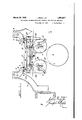
Further objects and advantages will become apparent as the description proceeds, 15 reference being had to the accompanying drawings; in which Figure 1 is a fragmentary elevation partly diagrammatic of the device mounted on the ordinary spinning frame: i
Figure 2 is a view on line 22 of Figure 1, and
Figure 3 is a section on line 3-3 of Figure 1.
Figure 4 is a plan view of the auxiliary the rollers and the central 25 frame showing depending arm.
In the proceeding inaccordance with the present invention a driving pulley or drum 1 is shown which is mounted and actuated in the usual manner. A pair of shaft brackets 2 and 3 are adjustably mounted on an ordinary spinning machine frame 4. The shaft brackets 2 and 3 are provided with inwardly extending projecting portions 5 which carry supporting shafts 6'. As shown in Figure 2'tl1e supporting shafts carry the entire idler pulley structure which letter is connected thereto by means ofsupporting members 7, and which maybe fixed in place by adjustment of set screws 8. Depending from the supporting members 7 is a U-shaped track-like member 9, which is formed from sheet metal and has the free ends of the U' turned inwardly to provide track surfaces for rollers 10 and 10. The roller 10supports axially bearing cradle structures 11 and at the same time actto support one end of the auxiliary frame 12, and the roller'lO supports a similar structure, that is, a bearingcradle structure 11 and theopposite end (III 1931.- Serial 1%. 540,844.
of the auxiliary frame 12. From the center of the auxiliary frame 12 a depending'arm 13 is provided and has a hub 14 at its lower end. .A shaft 15 extends axially through the hub 14 and carries a weight 16 at one end; and a crank arm 17 at the other.
connected to each end of the crank arm 17 Pivotally are links 18 and 19 which are pivotally connected at their outer ends to the carrying brackets 20 of the bearing cradles 11. The 1 links18 and 19are connected at the inner side of the crank arm 17 so that they will be in position to contact the hub 14 in'case the Weight 16 tends to move them beyond their normal position. In this manner the weight 16 is kept from dropping completely down and necessitating readjustment of the'component parts of the idler-pulley system.
. Should the driving tape T slip from the pulley A or B, stop ears 20 carried by the bearing cradle 11 will act to keep the tape from falling down :on the driving mechanism.
' In operation, and assuming the direction of rotation to be indicated by the arrow on the driving pulley, it willbe seen that pulley B and thecarriage structure carried by the rollers 10 will move to the left. The motionwill continue until thebearing yoke 11 contacts the dependingstop member 22. In
this position, pulley B becomes-the idler pulley and the weight 16 acts on the pulley A through link 19 and urges it inward thus tensioning the tape T and assuring a positive drive at all times. If the direction of rotation is reversed the similar action will provide pulley A as the idler pulley and pulley rollers in said track member, an auxiliary frame carried between said pairs of rollers, a hub depending centrally from said auxiliary frame, a Weight disposed at one side of and connected to said hub, a crank arm disposed a-t'the opposite side of said hub and operative by said weight, a pairrof links pivotally connected to opposite ends of said crank arm, a pair of brackets each carried between one pair of said spaced-rollergbearing cradles carried by each of said brackets and connected to the opposite :ends of said links, pulleys carried'by each of said bearing cradles, stop members depending fromrthe 35 track member and adapted to limit the lateralimovement of said bearing cradles by iengagenient -stherezwith, and means :to drive Visa-id pulleysfrom said driving means. rQQ-In a-device ofzthe class described, a
32: ."frame, spindle driving. means carried by said frame, a trackmember carried b said frame, :rollers carried-.insaid trackmem er,'an auxil- -iary;frame connecting the rollers, a hub deipending from said auxiliary frame, a Weight 35 disposed at one side ofand-connected'to said ill'llb, a crank arm connected to the opposite ,sideof said 'hub and operable'bysaid Weight, :a pair of bearing cradles, means to connect z sai d bearing cradlesxto saidauxiliary frame,
00 ;1neans to connect saidbearing'cradles to said .crankiarm whereby said bearing cradles are urgedstoward each otherbythe actionof said Weight, pulleys carried in said bearing :cradles 'and meansto drive;the p.ulleys; from 35 :said driving means. a
13. In a device of the class described, a frame, spindle driving means carried b said frame, a track member carried'by said rame,
- rollers carried-'in said track member, an auxil 10 :iary frame connecting said rollers, a hub "depending from said auxiliary frame, a pairxof Jbearing cradles carried by said uauxiliary "frame, :means connected to cthe auxiliary 'frame and said bearing cradles whereby to 335 urge the pulleys carried in said bearing cradles'ioward each other and means tozdrive Jthe ;pulleys from said driving means.
In :testi-mony'zwhereof I have hereunto --s igne d my name.
ran 7 JOHN PERRY, JR.
Priority Applications (1)
| Application Number | Priority Date | Filing Date | Title |
|---|---|---|---|
| US540844A US1851937A (en) | 1931-05-29 | 1931-05-29 | Reversible spindle drive for spinning and twisting machines |
Applications Claiming Priority (1)
| Application Number | Priority Date | Filing Date | Title |
|---|---|---|---|
| US540844A US1851937A (en) | 1931-05-29 | 1931-05-29 | Reversible spindle drive for spinning and twisting machines |
Publications (1)
| Publication Number | Publication Date |
|---|---|
| US1851937A true US1851937A (en) | 1932-03-29 |
Family
ID=24157162
Family Applications (1)
| Application Number | Title | Priority Date | Filing Date |
|---|---|---|---|
| US540844A Expired - Lifetime US1851937A (en) | 1931-05-29 | 1931-05-29 | Reversible spindle drive for spinning and twisting machines |
Country Status (1)
| Country | Link |
|---|---|
| US (1) | US1851937A (en) |
Cited By (2)
| Publication number | Priority date | Publication date | Assignee | Title |
|---|---|---|---|---|
| US3589203A (en) * | 1969-07-28 | 1971-06-29 | Balance Technology Inc | Drive mechanism for balancing machine |
| US5346437A (en) * | 1993-09-20 | 1994-09-13 | R. R. Donnelley & Sons Company | Dual source drive system |
-
1931
- 1931-05-29 US US540844A patent/US1851937A/en not_active Expired - Lifetime
Cited By (2)
| Publication number | Priority date | Publication date | Assignee | Title |
|---|---|---|---|---|
| US3589203A (en) * | 1969-07-28 | 1971-06-29 | Balance Technology Inc | Drive mechanism for balancing machine |
| US5346437A (en) * | 1993-09-20 | 1994-09-13 | R. R. Donnelley & Sons Company | Dual source drive system |
Similar Documents
| Publication | Publication Date | Title |
|---|---|---|
| US1805326A (en) | Belt drive | |
| US1851937A (en) | Reversible spindle drive for spinning and twisting machines | |
| US1517961A (en) | Pneumatic lint clearer for warping machines | |
| US1869692A (en) | Spindle drive for spinning or twisting machines | |
| US1803186A (en) | Spindle-driving mechanism | |
| US1220304A (en) | Belt-gearing attachment for roller-shafts. | |
| US1796912A (en) | Controlling device for running webs | |
| US1738083A (en) | Web-roll-driving device | |
| US630813A (en) | Lap drawing and doubling machine. | |
| US1820310A (en) | Spindle driving mechanism | |
| US1860955A (en) | Spinning and twisting machine | |
| US2198179A (en) | Conveyer | |
| US1131167A (en) | Protector-guard for tension-pulleys of textile-machines. | |
| US1868438A (en) | Automatic belt take-up | |
| US1818685A (en) | Automatic belt adjuster | |
| US1255912A (en) | Machine for wearing in drive-chains. | |
| US2775414A (en) | Constant tension control mechanism | |
| US1519958A (en) | Drive for roving frames | |
| US535326A (en) | Woeth | |
| US3282488A (en) | Web conveying apparatus | |
| US2775263A (en) | Tension-responsive control | |
| US1911944A (en) | Warp beam winding machine | |
| US1934654A (en) | Spinning and twister frame | |
| US1649751A (en) | Driving mechanism of spinning and analogous machines | |
| US397629A (en) | Driving mechanism for spinning-spindles |