US1851934A - Bearing liner or sleeve - Google Patents
Bearing liner or sleeve Download PDFInfo
- Publication number
- US1851934A US1851934A US283109A US28310928A US1851934A US 1851934 A US1851934 A US 1851934A US 283109 A US283109 A US 283109A US 28310928 A US28310928 A US 28310928A US 1851934 A US1851934 A US 1851934A
- Authority
- US
- United States
- Prior art keywords
- projection
- sleeve
- metal
- bearing
- backing
- Prior art date
- Legal status (The legal status is an assumption and is not a legal conclusion. Google has not performed a legal analysis and makes no representation as to the accuracy of the status listed.)
- Expired - Lifetime
Links
Images
Classifications
-
- F—MECHANICAL ENGINEERING; LIGHTING; HEATING; WEAPONS; BLASTING
- F16—ENGINEERING ELEMENTS AND UNITS; GENERAL MEASURES FOR PRODUCING AND MAINTAINING EFFECTIVE FUNCTIONING OF MACHINES OR INSTALLATIONS; THERMAL INSULATION IN GENERAL
- F16C—SHAFTS; FLEXIBLE SHAFTS; ELEMENTS OR CRANKSHAFT MECHANISMS; ROTARY BODIES OTHER THAN GEARING ELEMENTS; BEARINGS
- F16C33/00—Parts of bearings; Special methods for making bearings or parts thereof
- F16C33/02—Parts of sliding-contact bearings
- F16C33/04—Brasses; Bushes; Linings
- F16C33/06—Sliding surface mainly made of metal
- F16C33/08—Attachment of brasses, bushes or linings to the bearing housing
-
- Y—GENERAL TAGGING OF NEW TECHNOLOGICAL DEVELOPMENTS; GENERAL TAGGING OF CROSS-SECTIONAL TECHNOLOGIES SPANNING OVER SEVERAL SECTIONS OF THE IPC; TECHNICAL SUBJECTS COVERED BY FORMER USPC CROSS-REFERENCE ART COLLECTIONS [XRACs] AND DIGESTS
- Y10—TECHNICAL SUBJECTS COVERED BY FORMER USPC
- Y10T—TECHNICAL SUBJECTS COVERED BY FORMER US CLASSIFICATION
- Y10T29/00—Metal working
- Y10T29/49—Method of mechanical manufacture
- Y10T29/49636—Process for making bearing or component thereof
- Y10T29/49643—Rotary bearing
- Y10T29/49647—Plain bearing
- Y10T29/49668—Sleeve or bushing making
- Y10T29/49677—Sleeve or bushing making having liner
Definitions
- This invention relates to improvements in ⁇ bearing sleeves or shells and has special reference to the production of such shells sized within the allowable limits or tolerances and .'i provided with projections on the backs of v the shells by which the shells or liners are doweled to the housings in which they are used, the dovveling projections being integral With the shells.
- shells or bearing liners are semi-cylindrical both inside and outside and have heretofore been produced ⁇ by 'cutting tools which necessitated the separate application of the doweling projections which was not I only expensive, but lacked that positive degree of accuracy as to position, size, etc.,
- my invention am enabled to produce accurately sized shells in large volume at low cost and either made wholly of Babbitt metal, or the like, or with a harder metal backing made of steel, brass or bronze and an inner lining or layer of babbitt or the like, and in each instance or type provided with an accurately placed and dimensioned doweling projection 4on the back of the' shell.
- the process consists in producing a harder metal back slightly shorter both circumferentially and longitudinally than the finished dimensions and slightly thicker radially.
- This harder metal backing preferably has the doweling projection on its back or outer surface at least partly formed, and maybe either perforated or solid.
- the back is then tinned to cause the Babbitt metal to adhere to the inner surface and the Babbitt metal, which forms the inner wearing surface of thesleeve when finished, is preferably cast in place in accordance with the method disclosed in my companion application, led August 20,1928, Serial Number 300,757.
- I may provide an excrescence on the inner side of the sleeve opposite to the projection on the back.
- the sleeve is then formed, sized and iinished in a pair of dies which accurately size the sleeve as to all dimensions, the dies being provided With one or more die openings through Which the excess Babbitt metal is extruded.
- the die is provided with an opening or pocket into which the partly'formed projection on the back of the sleeve is forced, the excrescence on the inner side of the sleeve, when such is used, assist-ing in this actlon.
- the Babbitt metal is forced through the opening to assist in filling the projection-forming pocket in the die.
- the eXcrescence on theinner surface furnishes the"metal forthis purpose as well as for applying pressure for expanding and forming the projection to accurately fill the pocket.
- Another advantage of the production of the projection in this manner is that without additional cost suitable or desired markings can be produced vupon the outer fiat surface of the projection in the forming process thus simplifying the designation of particular sleeves for special uses. lOr the marking may be a suitable trade-mark or a notification that the bearing has been produced under certain patents. i
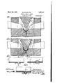
- FIG. 1 is a fragmentary, vertical sectional view of a plunger and co-operating die for forming the bearing sleeves, shown before the plunger enters the die;
- Fig. 2 is a view similar to Fig. 1 but showing the plunger and die as they appear at the close of the forming operation;
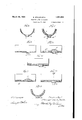
- Fig. 3 is a'central longitudinal section of one of the backings for a bearing sleeve.
- Fig. 4 is a central longitudinal section of a bearing sleeve taken on the line 4 4 of Fig. 1, and showing the backing with the Babbitt metal lining prepared for the final forming operation; s
- Fig. 5 is a central longitudinal section of the'v finished bearing and taken on the line 5--5 of Fig.2; l
- Fig. ⁇ 6 is a cross-section of the backingA sleeve on the line 6 6 of Fig. 3;
- Fig. 7 is a cross-section of the finishedsleeve j taken on the line 7-7 of Fig. 5;
- Fig. 8 is a view similar to Fig. 3, but showing a backing wherein the projection is not perforated; 10
- Fig. 9 is a'view similar to Fig. 4 but show ing a non-perforated projection on the l backing;
- his backing is preferably formed in a press out of sheet metal such as steel, bronze orl brass and inthe forming process is provided with a formed out projection 2 on its back which is preferably, though notnecessarily perforated being open at its bottom, as shown at 3, Fig. 3.
- This lining is preferably provided with a rounded excrescence 5 opposite to the projection 2 to provide metal to complete the interlocking projection.
- Figs. 1 and 2 herein I have illustrated such dies which roughly consist of a lower die member 6 having a semi-cylindrical die opening 7 in which the outer semi-cylindrical surface of the sleeve is sized.
- This die member is provided with a depression 8 in its bottomadapted to sizethe projection which it is desired to produce' upon the backofthe sleeve.
- the upper member 9 is moved up and down 'by means of a suitable press mechanism, not shown. When the upper die member enters make the whole sleeve of Babbitt metal.
- closures 11 for the upper edges of the die space are provided. These closures 11 also operate to define the extrusion slots at the sides of the die member 9 through which any excess Babbitt metal may be forced, as shown at 12, Fig. 2. v
- the first action of the plunger 9 is to contact with the excrescense 5 and force the'. Babbitt metal through the opening 3 and to fill the depression 8 in the bottom of the lower die.
- Fig. 8 is a longitudinal section of a prepared backing having a doweling projection 11 partly formed but the bottom 12 of which has not been cut out as in the former case.
- a semi-cylindrical bearing sleeve' accurately finished as to dimensions and surfaces and having an integral doweling projection on its outer surface, the sleeve having a Babbitt or similar bearing metal lining and a harder metal backing, the doweling projection including a hollow reformed projection on the back of the har er metal backing the bottom of such preformed projection perforated, and the Babbitt metal having been forced through said opening to form the outer end of the doweling projection.
- a bearing sleeve comprising an outer relatively thin backing of a relatively harder metal and an inner lining of a relatively softer bearing metal, the sleeve having an outer finished'cylindrical surface, a projection on said surface having a rim formed out of the
Landscapes
- Engineering & Computer Science (AREA)
- General Engineering & Computer Science (AREA)
- Mechanical Engineering (AREA)
- Forging (AREA)
Description
.M amh29, 1932. l a. sTocKF BEARING LINER Filed June Marchzs, 1932. B STOCKFLETH 1 1,851,934
BEARING LINER OR SLEEVE Filed June 5. 1928 2 Sheets-Sheet A2 www0 @y @im/@m Patented Mar. 29, 1932` UNITED STATES lPA'rlazNfu OFFICE BERGER STOCKFLETH, OF NILES, MICHIGAN, ASSIGNOR TO HYDRAULIC PRESSED BEAR- ING COMPANY, OF WILMINGTON, DELAWARE, A CORPORATION F DELAWARE BEARING LINER OR SLEEVE Application led June 5,
This invention relates to improvements in` bearing sleeves or shells and has special reference to the production of such shells sized within the allowable limits or tolerances and .'i provided with projections on the backs of v the shells by which the shells or liners are doweled to the housings in which they are used, the dovveling projections being integral With the shells.
These shells or bearing liners are semi-cylindrical both inside and outside and have heretofore been produced `by 'cutting tools which necessitated the separate application of the doweling projections which was not I only expensive, but lacked that positive degree of accuracy as to position, size, etc.,
Which is an essential in modern high speed interchangeable production.
By means of my invention I am enabled to produce accurately sized shells in large volume at low cost and either made wholly of Babbitt metal, or the like, or with a harder metal backing made of steel, brass or bronze and an inner lining or layer of babbitt or the like, and in each instance or type provided with an accurately placed and dimensioned doweling projection 4on the back of the' shell.
In the hereindescribed method of producing such bearing liners, the process applies 3 more particularly to liners which have harder metal backs.
The process consists in producing a harder metal back slightly shorter both circumferentially and longitudinally than the finished dimensions and slightly thicker radially. This harder metal backing preferably has the doweling projection on its back or outer surface at least partly formed, and maybe either perforated or solid. The back is then tinned to cause the Babbitt metal to adhere to the inner surface and the Babbitt metal, which forms the inner wearing surface of thesleeve when finished, is preferably cast in place in accordance with the method disclosed in my companion application, led August 20,1928, Serial Number 300,757. In
the'casting of the Babbitt metal upon the backing, I may provide an excrescence on the inner side of the sleeve opposite to the projection on the back.
1928. Serial N0. 283,109.
The sleeve is then formed, sized and iinished in a pair of dies which accurately size the sleeve as to all dimensions, the dies being provided With one or more die openings through Which the excess Babbitt metal is extruded. The die is provided with an opening or pocket into which the partly'formed projection on the back of the sleeve is forced, the excrescence on the inner side of the sleeve, when such is used, assist-ing in this actlon.
In the case of the partly formed projection being perforated, the Babbitt metal is forced through the opening to assist in filling the projection-forming pocket in the die. In this case the eXcrescence on theinner surface furnishes the"metal forthis purpose as well as for applying pressure for expanding and forming the projection to accurately fill the pocket.
Another advantage of the production of the projection in this manner is that without additional cost suitable or desired markings can be produced vupon the outer fiat surface of the projection in the forming process thus simplifying the designation of particular sleeves for special uses. lOr the marking may be a suitable trade-mark or a notification that the bearing has been produced under certain patents. i
MyI invention will be more readily under; stood by reference to the accompanying draw'- ings forming part of the specification and in which-L Fig. 1 is a fragmentary, vertical sectional view of a plunger and co-operating die for forming the bearing sleeves, shown before the plunger enters the die;
Fig. 2 is a view similar to Fig. 1 but showing the plunger and die as they appear at the close of the forming operation;
Fig. 3 is a'central longitudinal section of one of the backings for a bearing sleeve.
Fig. 4 is a central longitudinal section of a bearing sleeve taken on the line 4 4 of Fig. 1, and showing the backing with the Babbitt metal lining prepared for the final forming operation; s
Fig. 5 is a central longitudinal section of the'v finished bearing and taken on the line 5--5 of Fig.2; l
Fig.` 6 is a cross-section of the backingA sleeve on the line 6 6 of Fig. 3;
Fig. 7 is a cross-section of the finishedsleeve j taken on the line 7-7 of Fig. 5;
Fig. 8 is a view similar to Fig. 3, but showing a backing wherein the projection is not perforated; 10
Fig. 9 is a'view similar to Fig. 4 but show ing a non-perforated projection on the l backing;
roduction of my improved bearing lining.
his backing is preferably formed in a press out of sheet metal such as steel, bronze orl brass and inthe forming process is provided with a formed out projection 2 on its back which is preferably, though notnecessarily perforated being open at its bottom, as shown at 3, Fig. 3.
In the process of producing a bearing lining or sleeve the next step is to tin the blankv back 1 and then cast a Babbitt metal lining within the backing, as shown atv4, Fig. 4..'
This lining is preferably provided with a rounded excrescence 5 opposite to the projection 2 to provide metal to complete the interlocking projection. Having produced the Babbitt metal lining 4 preferably in accordance with thevmethod disclosed in my said 'copending application, I next proceed to com' plete the bearing'sleeve by applying a heavy pressure thereto in dies made for the purpose.
Suitable dies and their operation are fully disclosed in U. S. Patent No 1,722,995, issued to Frederick W. Burger and Berger Stockleth on August 6, 1929.
j In Figs. 1 and 2 herein, I have illustrated such dies which roughly consist of a lower die member 6 having a semi-cylindrical die opening 7 in which the outer semi-cylindrical surface of the sleeve is sized. This die member is provided with a depression 8 in its bottomadapted to sizethe projection which it is desired to produce' upon the backofthe sleeve. There is a co-operating plunger on die member 9 having a semi-cylindrical lower end 9 which co-operates with the opening 7 to form the inner surface of the sleeve.
The upper member 9 is moved up and down 'by means of a suitable press mechanism, not shown. When the upper die member enters make the whole sleeve of Babbitt metal.
the lower member and is forced down to its limit, it is forced down with sufficient pressure to cause the lBabbitt metal linin 4, which is thicker radially than the finishe product, to be thinned out and at the final position of the dies the radial thickness is that which is desired in the finished sleeve. To prevent the circumferential elongation of the backing beyond the dimensions of the finished shell, closures 11 for the upper edges of the die space are provided. These closures 11 also operate to define the extrusion slots at the sides of the die member 9 through which any excess Babbitt metal may be forced, as shown at 12, Fig. 2. v
In this pressing step the first action of the plunger 9 is to contact with the excrescense 5 and force the'. Babbitt metal through the opening 3 and to fill the depression 8 in the bottom of the lower die.
The tremendous pressure to which the metal is subjected causes it to completely fill the depression 8 and even causes the thimble 2 to expand and be sized on its outer surface by the wall of the depression 8, forcing the Babbitt metal out'through the opening and forming a Babbitt metal button 10 at the outer end of the projection 2, thus completing and finishing the doweling projection as shown at 10, Figs. 5 and 7. It is obvious that any marking desired can be impressed in the outer flat surface of the finished doweling projection, as shown in Fig. 2, by merely building up the design wanted on the bottom of the depression 8.'
In some instances it is best not to cut out the bottom of the partly formed projection and Figs. 8, 9 and 10 illustrate this method.
Fig. 8 is a longitudinal section of a prepared backing having a doweling projection 11 partly formed but the bottom 12 of which has not been cut out as in the former case.
The following procedure is quite similar to that already described in that after the backing is partly formed, as shown in Fig. 8, it is then tinned and the Babbitt metal lining 13 is cast in place, thicker radially than the finishing lining and with an excrescence 14 on the inslde opposite to the partly formed dowelin projection 11. Then the sleeve is formed y pressure as already described, the first action being to press down on the excrescence 14 causing the Babbitt metal to force the partly formed doweling projection 11 down into the depression 8 in thelower die member and thus accurately finish and size the doweling projection'at the same time that the shell is completed'in the press. This completed doweling projection is shown at 15, Fig. 10. j
Under some conditions it is not desired to make use of a harder metal backing but to For this purpose it is preferred to cast a sleeve blank preparatory to the forming step but will readily suggest themselves to such is not an absolute necessit ,it being necessary merely that suicient labbitt metal be present inthe lower die so that when the uppermember is forced in to its limit all of the die space will be completely filled with the Babbitt metal.
When a pre-cast sleeve blank is used, as shown in Fig. 11, at 16, it, like the previously described sleeves is provided With an excresc ence 17 on its inner side and opposite to the place where the doweling projection is desired. During the pressing step ythe Babbitt metal is forced out into the dowel depression 8 in the lower die producing the finished dowel projection, as shown at 18 Figs. 12 and 13.
It is thus seen that by means of this invention a solid or integral doweling projection is cheaply and accurately produced upon the back of a finished bearing sleeve.
As many modifications of my invention one skilled in the vart I do not limit or confine my invent-ion to the specific details of construction or method steps herein described and claimed.
`The improved method herein illustrated and described is not claimed herein, such forming the subject matter of my co-pendin application filed February 29, 1932, Sera No. 595,885.
l. A semi-cylindrical bearing sleeve, accu-- ratel finished as to dimensions and surfaces and aving an integral doweling projection on its outer surface, the sleeve having a Babbitt or similar bearing metal lining and a harder metal backing, the doweling vprojection including a hollow preformed projection on the back of the harder metal backing.
2. A semi-cylindrical bearing sleeve', accurately finished as to dimensions and surfaces and having an integral doweling projection on its outer surface, the sleeve having a Babbitt or similar bearing metal lining and a harder metal backing, the doweling projection including a hollow reformed projection on the back of the har er metal backing the bottom of such preformed projection perforated, and the Babbitt metal having been forced through said opening to form the outer end of the doweling projection. l
3. A bearing sleeve'comprising an outer relatively thin backing of a relatively harder metal and an inner lining of a relatively softer bearing metal, the sleeve having an outer finishedcylindrical surface, a projection on said surface formed partly from the metal of the backing and partly from the metal of the lining@v sleeve comprising an outerbearing metal, the metal of the back formed outwardly to provide a hollow projectlon on said outer cylindrical surface, and the metal of the lining filling said projection.
In witness that I claim the fore oing as my invention, I aix my signature t is 12th dayof May, 1928. v
- BERGER STOCKFLETH.
4. A bearing sleeve comprising an outer relatively thin backing of a relatively harder metal and an inner lining of a relatively softer bearing metal, the sleeve having an outer finished'cylindrical surface, a projection on said surface having a rim formed out of the
Priority Applications (2)
| Application Number | Priority Date | Filing Date | Title |
|---|---|---|---|
| US283109A US1851934A (en) | 1928-06-05 | 1928-06-05 | Bearing liner or sleeve |
| US595885A US1942578A (en) | 1928-06-05 | 1932-02-29 | Method of making bearing sleeves |
Applications Claiming Priority (1)
| Application Number | Priority Date | Filing Date | Title |
|---|---|---|---|
| US283109A US1851934A (en) | 1928-06-05 | 1928-06-05 | Bearing liner or sleeve |
Publications (1)
| Publication Number | Publication Date |
|---|---|
| US1851934A true US1851934A (en) | 1932-03-29 |
Family
ID=23084559
Family Applications (1)
| Application Number | Title | Priority Date | Filing Date |
|---|---|---|---|
| US283109A Expired - Lifetime US1851934A (en) | 1928-06-05 | 1928-06-05 | Bearing liner or sleeve |
Country Status (1)
| Country | Link |
|---|---|
| US (1) | US1851934A (en) |
Cited By (3)
| Publication number | Priority date | Publication date | Assignee | Title |
|---|---|---|---|---|
| US2482381A (en) * | 1945-03-17 | 1949-09-20 | Ford Motor Co | Method of testing bearings |
| US2722291A (en) * | 1952-02-29 | 1955-11-01 | Chicago Malleable Castings Com | Brake beam construction |
| US10087984B2 (en) | 2015-06-30 | 2018-10-02 | Saint-Gobain Performance Plastics Corporation | Plain bearing |
-
1928
- 1928-06-05 US US283109A patent/US1851934A/en not_active Expired - Lifetime
Cited By (3)
| Publication number | Priority date | Publication date | Assignee | Title |
|---|---|---|---|---|
| US2482381A (en) * | 1945-03-17 | 1949-09-20 | Ford Motor Co | Method of testing bearings |
| US2722291A (en) * | 1952-02-29 | 1955-11-01 | Chicago Malleable Castings Com | Brake beam construction |
| US10087984B2 (en) | 2015-06-30 | 2018-10-02 | Saint-Gobain Performance Plastics Corporation | Plain bearing |
Similar Documents
| Publication | Publication Date | Title |
|---|---|---|
| US2762118A (en) | Method of forming an interlocking bushing | |
| US1976776A (en) | Eyelet | |
| US2227969A (en) | Rubber bearing or the like and method of making the same | |
| US1331961A (en) | Lined bearing | |
| US1851934A (en) | Bearing liner or sleeve | |
| JPH11169980A (en) | Formation of flanged and stepped cup like-product | |
| US1942578A (en) | Method of making bearing sleeves | |
| US3199173A (en) | Method of making a flanged bearing | |
| US2119900A (en) | Manufacture of bearings | |
| US2112697A (en) | Method of making brake drums | |
| US2014605A (en) | Means for forming roller bearing cups | |
| US1867412A (en) | Method of making bearings | |
| US1922304A (en) | Bearing manufacture | |
| US1512190A (en) | Bearing and method of making the same | |
| US1597428A (en) | Bearing and method of making it | |
| US1481000A (en) | Method of making ball retainers and the like | |
| US1892180A (en) | Method of making bearing sleeves | |
| US2770034A (en) | Method of coining and cupping metal | |
| US2137537A (en) | Process of die casting and assembling expansion shields or anchors | |
| US1892175A (en) | Method of making bearing sleeves | |
| US1646371A (en) | Bearing and method of making same | |
| US1821122A (en) | Bearing sleeve and method of making same | |
| US2137538A (en) | Process of die casting and assembling expansion shields | |
| US2138268A (en) | Brake drum machine | |
| US1772354A (en) | Method of forming integrally-joined sheets of dissimilar metals |