US1851930A - Oil immersed current distributing panel - Google Patents
Oil immersed current distributing panel Download PDFInfo
- Publication number
- US1851930A US1851930A US512945A US51294531A US1851930A US 1851930 A US1851930 A US 1851930A US 512945 A US512945 A US 512945A US 51294531 A US51294531 A US 51294531A US 1851930 A US1851930 A US 1851930A
- Authority
- US
- United States
- Prior art keywords
- housing
- opening
- oil
- panel
- wall
- Prior art date
- Legal status (The legal status is an assumption and is not a legal conclusion. Google has not performed a legal analysis and makes no representation as to the accuracy of the status listed.)
- Expired - Lifetime
Links
Images

Classifications
-
- H—ELECTRICITY
- H02—GENERATION; CONVERSION OR DISTRIBUTION OF ELECTRIC POWER
- H02B—BOARDS, SUBSTATIONS OR SWITCHING ARRANGEMENTS FOR THE SUPPLY OR DISTRIBUTION OF ELECTRIC POWER
- H02B1/00—Frameworks, boards, panels, desks, casings; Details of substations or switching arrangements
Definitions
- My invention relates to distributing panels and particularly to enclosed oil-immersed panels for use in the presence of deleterious gases, such as are prevalent in chemical factories and the like.
- An object of my invention is to provide an oil-immersed distributing panelboard wherein the panel units are mounted in a fixed housing in such manner that the panel units containing the current-controlling devices, such as fuses and switches, are immersed in oil, and the panel containing the terminals for the feed and load conductors is so mounted that the conductor terminals are above the level of the oil in the housing and are, therefore, readily accessible for altering load-circuit connections without removal of the oil.
- a further object of my invention is to provide an oil-immersed distributing panelboard, having the above noted characteristics, wherein the panel unit containing the current-controlling devices is mounted upon the bottom wall of a rectangular housing and is immersed in insulating liquid, and wherein the panel unit containing the conductor terminals is mounted at right angles to the panel unit containing the circuit-controlling devices and upon the rear wall of the housing, and wherein the opening in the housing is disposed in a plane substantially normal to a line bisecting the angle of the panel units in order that all parts of the devices and terminals mounted: on the panel units may be accessible through the opening in the housing and in such position that a screw driver or other implement may be inserted through the opening for manipulation of the fastening screws which serve to secure the current-controlling devices and the terminals to their respective panel units.
- a further object of my invention is to provide an oil-immersed distributing panelboard of the character defined above, wherein the usual removable tank is eliminated and wherein the removal of a cover renders all of the parts of the panel units accessible for inspection, repair or alteration.
- a further object of my invention is to provide an oil-immersed distributing panelboard of compact construction and design wherein the head room required is reduced to a minimum and which is relatively inexpensive to manufacture.
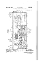
- Figure 1 is an elevational View of an oilimmersed distributing panel embodying features of my invention, a portion of the casing being cut away for the purpose of clearness of illustration, and
- Fig. 2 is an elevational view, in vertical section, of the apparatus shown in Fig. 1, taken on the line II-II thereof.
- the oil-immersed distributing panel comprises a housing 3, preferably made of cast iron, which comprises a bottom wall 4, a rear Wall 5, a front wall 6, end walls 7 and a top wall 8, the housing having supporting brackets 9 by means of which the housing may be secured to a wall or other support, holes 11 being provided in the upper brackets for receiving securing bolts, and the lower bracket being provided with a slot 12 for the same purpose.
- an opening 14: which extends type snap switch throughout the length of the housing, is provided in a plane substantially normal to a line bisecting the angle between the bottom wall 4 and the rear wall 5. This disposition of the opening 14 renders anything mounted upon the bottom and rear walls readily accessible through the opening, as is apparent in Fig. 2.
- two panel units 15 and 16 preferably made of insulating material, are mounted, the former comprising an insulating base block that is attached to the rear wall 5 of the housing and upon which metal terminal blocks 17 are secured by means of screws 18, the blocks serving to support the neutral terminals 19 of a three-phase four-wire feed circuit, and a plurality of terminal screws 21 to which a load conductor for each load circuit is connected.
- the panel unit 15 also supports the three feed conductors 22, 23 and 24 of the three phase feed circuit, referred to above, and a plurality of terminal straps 25 having terminalbolts 26 to which the other conductors of the load circuits are connected.
- the terminal straps 25 also are provided with terminal-attaching screws 27, the purpose of which will hereinafter appear.
- the panel unit 15 is secured to the rear, wall 5 by means of screws 28, and the unit is maintained in spaced relation to the rear wall 5 of the housing by means of insulating washers 29, the space permitting free circulation of the oil and atmosphere within the housing, by reason of convection currents, thereby facilitating cooling of the panel unit.
- the panel unit 16 is secured to the bottom wall 4 of the housing by screws 31, and the unit is maintained inspaced relation to the bottom wall 4 by means of insulating washers 32, the space permitting of free circulation ofthe oil around the insulating base.
- the panel unit 16 is provided with a pair of sub-bases 33 made of insulating material, the bases being secured to the unit 16 by bolts 34 and serving to support fuse-terminal clips 35 and 36 which receive the terminals 37 of a cartridge fuse 38, the latter being mounted in a detachable fuse clip 39 made of insulating material and may be gripped by the fingers of the operator for the purpose of removing it from its terminal clips.
- a pair of fuse clips 35 and 36 is provided for each load circuit, and, in the construction herein illustrated, the distributing panel is provided with facilities for controlling twelve load circuits that are divided in groups of four for each of the feed conductors 22, 23 and 24.
- V Upon the panel unit 16, opposite each pair of fuse clips 35 and 36, is mounted a tumbler- 41','of any preferred construction, which comprises a pair of contact members 42 and 43 and a bridging contact blade 44 which serves to conductively connectthe said contact members.
- the blades are pivotally mounted upon asupporting frame 45, and are operated to open and closed positions by 'a snap action, in response to movement of an operating handle 46 made of insulating material and having the usual lostmotion spring connection to the bridging switch blade 44. Switches of this character are well known in the art and, as no claim is, made to its special construction, no further description of its details is necessary.
- the fuse clip 36 is connected to the switch contact blade 42 through a conductor strap 47, and the switch contact blade 43 is conductively connected to any one of the conductor straps 48, 49 and 51, mounted upon the panel unit 16, depending upon which group of four switches the switch constitutes a part.
- the conductor straps 48, 49 and 51 are connected, respectively, to the terminals 22, 23 and 24 through the medium of extension straps 52, 53 and 54, respectively
- the fuse clips 35 are provided with conductor terminals 55 for securing flexible-conductor links 56 thereto, the links being individually connected to separate terminal straps 25.
- the end wall 7 of the housing 3 is'provided with an opening 57 to which the usual conduit trough (not shown) is connected, in a well known manner, and through which the feed conductors lead into the housing, it being understood that the feed conductors (not shown) are connected to the terminals 19, 22, 23 and 24 and that the load conductors also extend out of the housing through the opening 57 and through the conduit associated therewith.
- a circuit through a load circuit 58 may be'traced as follows: from the load conductor connected to the terminal 22, through extension conductor 52, conductor strap 48, switch contact member 43, bridging switch blade 44, switch contact member 42, conductor strap 47 ,Vfuse clip 36, fuse 38, fuse clip 35, conductor link 56, terminal screw 27, terminal strap 25, terminal-screw 26, load conductor 59, load 61, load conductor 62, terminal screw 21, neutral terminal block 17 and neutral feed terminal 19, to the neutral feed conductor (not shown).
- the voperating handlesv 46 of the switches 41 are pivotally connected to operating push rods 63,.one for each switch, by means of connecting links 64, and each push rod extends through an opening having a packing gland 66 which surrounds the rod and prevents exit of oil and ingress of deleterious gases, and each rod is provided with an operating handle 67 that may be gripped by the fingers of the operator and pushed inwardly to the position shown in'Fig. 2 for the purpose of moving the switch to the open position shown, or which may be. pulled outwardly to the position shown in broken lines for the purpose of moving the switch contact blade to closed position.
- a door or cover 68 which is preferably mad of cast iron and is provided with an annular groove 69 in its inner face for receiving yielding gas-tight packing material 71 which is pressed into intimate con tact with the flanged edges of the side and front ends and top wall of the housing which constitute the boundary of the opening 14, to thereby provide a gas-tight seal for the housing.
- the housing is provided, at each end, with clamp screws 7 2 having their free ends threaded to receive wing nuts 73, and the cover, which extends beyond the end walls of the housing, is provided with openings through which the clamp screws 72 ex tend when the wing nuts are screwed upon the clamp screws 72, the cover being securely clamped in sealing position upon the housing.
- the housing is supplied with oil, or other insulating liquid, to the level A, indicated in dotted lines in Fig. 2, the oil completely immersing the switches and the cartridge fuses, thus protecting them from deleterious gases.
- the terminals 26, 19, 22, 23, 24 and 21 are located above the oil level, and alterations in the connections may be made without draining the oil from the housing, the terminals all being readily accessible through the opening 14, as is apparent in Fig. 2.
- the switches and fuses are readily accessible through the opening 14 when the cover is removed and, in the event that it is desired to inspect the fuse clips or switches, the oil may be drained from the housing by removing a drain plug 74 located in the bot tom wall 4 of the housing.
- fuse-carrier clips 39 are disposed above the fluid level A, fuses may be changed without requiring immersion of the hands of the operator in the oil, and it will be noted that, when the switch associated with any particular fuse is open, the feed conductor is disconnected from the fuse, thereby rendering it safe for fuse removal.
- a liquid-immersed distributing panelboard comprising a rectangular housing for containing an insulating liquid and having the upper portion of its front wall cut away to provide an opening in the front upper corner of the casing, panel units mounted on the bottom Wall and the rear wall where they are readily accessible through the said opening, the panel unit on the bottom wall being immersed in the liquid, and a cover for the said opening.
- a liquid-immersed distributing panelboard comprising a rectangular housing for containing an insulating liquid and having the upper portion of its front wall and the front portion of its top wall cut away to provide an opening in the front upper corner of the casing, the plane of which is substantially normal to a line bisecting the angle of the bottom and rear walls, panel units mounted on the bottom wall and the rear wall where they are readily accessible through the said opening, the panel unit on the bottom wall being immersed in the liquid, and a cover for the said opening.
- a liquid-immersed distributing panelboard comprising a rectangular housing for containing an insulating liquid and having the upper portion of its front wall and the front portion of its top wall cut away to provide an opening in the front upper corner of the casing, the plane of which is substantially normal to a line bisecting the angle of the bottom and rear walls, panel units mounted on the bottom wall and the rear wall where they are readily accessible through the said opening, the panel unit on the bottom wall being immersed in the liquid and containing current-controlling devices, operating members connected to the devices and extending through openings in the casing above the level of the fluid in the housing, and operable exteriorly thereof, and a cover for the first said opening.
- a liquid-immersed distributing panelboard comprising a rectangular housing for containing an insulating liquid and having the upper portion of its front wall and the front portion of its top wall cut away to provide an opening in the front upper corner of the casing, the plane of which is substantially normal to a line bisecting the angle of the bottom and rear walls, panel units mounted on the bottom wall and the rear wall where they are readily accessible through the said opening, the panel unit on the bottom wall being immersed in the liquid and containing current-controlling devices, and the panel unit on the rear wall containing terminals for the load conductors that are disposed above the level of the fluid in the housing for facilitating connection alterations without removing the liquid, and a cover for the said opening.
- a liquid-immersed distributing panelboard comprising a housing for containing insulating liquid having the upper edge of its front wall lower than the top portion of the rear wall and its top wall extending from the rear wall and terminating at a point substantially behind the front wall to provide an opening in the upper front corner of the housinga distributing panel containing current-controlling devices mounted on the bottom Wall and immersed in the insulating fluid, a terminal panel mounted on the rear Wall and having terminals thereon for receiving feed and load'conductors, the said panels being readily accessible through the said opening, and a movable cover for the said opening.
Landscapes
- Engineering & Computer Science (AREA)
- Power Engineering (AREA)
- Connections Arranged To Contact A Plurality Of Conductors (AREA)
Description
March 29, 1932'. H. G. BAXTER 51,
OIL TMMERSED CURRENT DISTRIBUTING PANEL Filed Feb. 2, 1931 2 Sheets-Sheet 1 WITNESSESI lNVENTOR I ATTORNEY March 29, 1932. I H G B T 1,851,930
OIL IMMERSED CURRENT DISTRIBUTING PANEL Filed Feb. 2, 1931 2 Sheets-Sheet 2 '1 "'7' I], N 5 32 l l6 3/ WITNESSES; INVENTOR F29- Haro/dGZBaxfer B V (A/2171i??? Patented Mar. 29, 1932 TES ATENT OFFIOE HAROLD G. BAXTER, OF BALDWIN, NEW YO & MANUFACTURING COMPANY, A
OIL IMMERSED CURRENT DISTRIBUTING PANEL Application filed February 2, 1931. Serial No. 512,945.
I My invention relates to distributing panels and particularly to enclosed oil-immersed panels for use in the presence of deleterious gases, such as are prevalent in chemical factories and the like.
In the copending application, Serial No. 330,450, filed January 5, 1929, to H. G. Baxter and G. G. Shannonhouse, and my copending application, Serial No. 362,685, filed May 13, 1929, and assigned to the assignee of the present application, are disclosed distributing panelboards that are suspended from fixed covers and enclosed by removable tanks containing insulating liquid, such as oil, the circuit-controlling devices, mounted upon the panelboard, being immersed in the liquid for preventing any access thereto of deleterious gases that would ordinarily attack the metals used in the circuit-controlling devices and cause corrosion thereof, with resultant dangerous heating of the pa-nelboard and energy losses.
An object of my invention is to provide an oil-immersed distributing panelboard wherein the panel units are mounted in a fixed housing in such manner that the panel units containing the current-controlling devices, such as fuses and switches, are immersed in oil, and the panel containing the terminals for the feed and load conductors is so mounted that the conductor terminals are above the level of the oil in the housing and are, therefore, readily accessible for altering load-circuit connections without removal of the oil.
A further object of my invention is to provide an oil-immersed distributing panelboard, having the above noted characteristics, wherein the panel unit containing the current-controlling devices is mounted upon the bottom wall of a rectangular housing and is immersed in insulating liquid, and wherein the panel unit containing the conductor terminals is mounted at right angles to the panel unit containing the circuit-controlling devices and upon the rear wall of the housing, and wherein the opening in the housing is disposed in a plane substantially normal to a line bisecting the angle of the panel units in order that all parts of the devices and terminals mounted: on the panel units may be accessible through the opening in the housing and in such position that a screw driver or other implement may be inserted through the opening for manipulation of the fastening screws which serve to secure the current-controlling devices and the terminals to their respective panel units.
A further object of my invention is to provide an oil-immersed distributing panelboard of the character defined above, wherein the usual removable tank is eliminated and wherein the removal of a cover renders all of the parts of the panel units accessible for inspection, repair or alteration. A further object of my invention is to provide an oil-immersed distributing panelboard of compact construction and design wherein the head room required is reduced to a minimum and which is relatively inexpensive to manufacture.
These and other objects of my invention, that will be made apparent throughout the further description thereof, are attained by means of the apparatus hereinafter described, and illustrated in the accompanying drawings, wherein Figure 1 is an elevational View of an oilimmersed distributing panel embodying features of my invention, a portion of the casing being cut away for the purpose of clearness of illustration, and
Fig. 2 is an elevational view, in vertical section, of the apparatus shown in Fig. 1, taken on the line II-II thereof.
Referring to the drawings, the oil-immersed distributing panel comprises a housing 3, preferably made of cast iron, which comprises a bottom wall 4, a rear Wall 5, a front wall 6, end walls 7 and a top wall 8, the housing having supporting brackets 9 by means of which the housing may be secured to a wall or other support, holes 11 being provided in the upper brackets for receiving securing bolts, and the lower bracket being provided with a slot 12 for the same purpose.
As indicated in Fig. 2, the upper edge 13 of the front wall 6 is of less height than the rear wall 5, and the top wall 8 is of less width than the bottom wall 4:. By reason of this construction, an opening 14:, which extends type snap switch throughout the length of the housing, is provided in a plane substantially normal to a line bisecting the angle between the bottom wall 4 and the rear wall 5. This disposition of the opening 14 renders anything mounted upon the bottom and rear walls readily accessible through the opening, as is apparent in Fig. 2.
Within the housing, two panel units 15 and 16, preferably made of insulating material, are mounted, the former comprising an insulating base block that is attached to the rear wall 5 of the housing and upon which metal terminal blocks 17 are secured by means of screws 18, the blocks serving to support the neutral terminals 19 of a three-phase four-wire feed circuit, and a plurality of terminal screws 21 to which a load conductor for each load circuit is connected.
The panel unit 15 also supports the three feed conductors 22, 23 and 24 of the three phase feed circuit, referred to above, and a plurality of terminal straps 25 having terminalbolts 26 to which the other conductors of the load circuits are connected. The terminal straps 25 also are provided with terminal-attaching screws 27, the purpose of which will hereinafter appear.
The panel unit 15 is secured to the rear, wall 5 by means of screws 28, and the unit is maintained in spaced relation to the rear wall 5 of the housing by means of insulating washers 29, the space permitting free circulation of the oil and atmosphere within the housing, by reason of convection currents, thereby facilitating cooling of the panel unit.
The panel unit 16 is secured to the bottom wall 4 of the housing by screws 31, and the unit is maintained inspaced relation to the bottom wall 4 by means of insulating washers 32, the space permitting of free circulation ofthe oil around the insulating base. The panel unit 16 is provided with a pair of sub-bases 33 made of insulating material, the bases being secured to the unit 16 by bolts 34 and serving to support fuse-terminal clips 35 and 36 which receive the terminals 37 of a cartridge fuse 38, the latter being mounted in a detachable fuse clip 39 made of insulating material and may be gripped by the fingers of the operator for the purpose of removing it from its terminal clips. A pair of fuse clips 35 and 36 is provided for each load circuit, and, in the construction herein illustrated, the distributing panel is provided with facilities for controlling twelve load circuits that are divided in groups of four for each of the feed conductors 22, 23 and 24. V Upon the panel unit 16, opposite each pair of fuse clips 35 and 36, is mounted a tumbler- 41','of any preferred construction, which comprises a pair of contact members 42 and 43 and a bridging contact blade 44 which serves to conductively connectthe said contact members. The blades are pivotally mounted upon asupporting frame 45, and are operated to open and closed positions by 'a snap action, in response to movement of an operating handle 46 made of insulating material and having the usual lostmotion spring connection to the bridging switch blade 44. Switches of this character are well known in the art and, as no claim is, made to its special construction, no further description of its details is necessary.
The fuse clip 36 is connected to the switch contact blade 42 through a conductor strap 47, and the switch contact blade 43 is conductively connected to any one of the conductor straps 48, 49 and 51, mounted upon the panel unit 16, depending upon which group of four switches the switch constitutes a part. The conductor straps 48, 49 and 51 are connected, respectively, to the terminals 22, 23 and 24 through the medium of extension straps 52, 53 and 54, respectively The fuse clips 35 are provided with conductor terminals 55 for securing flexible-conductor links 56 thereto, the links being individually connected to separate terminal straps 25. j
The end wall 7 of the housing 3 is'provided with an opening 57 to which the usual conduit trough (not shown) is connected, in a well known manner, and through which the feed conductors lead into the housing, it being understood that the feed conductors (not shown) are connected to the terminals 19, 22, 23 and 24 and that the load conductors also extend out of the housing through the opening 57 and through the conduit associated therewith.
For example, a circuit through a load circuit 58 may be'traced as follows: from the load conductor connected to the terminal 22, through extension conductor 52, conductor strap 48, switch contact member 43, bridging switch blade 44, switch contact member 42, conductor strap 47 ,Vfuse clip 36, fuse 38, fuse clip 35, conductor link 56, terminal screw 27, terminal strap 25, terminal-screw 26, load conductor 59, load 61, load conductor 62, terminal screw 21, neutral terminal block 17 and neutral feed terminal 19, to the neutral feed conductor (not shown).
The voperating handlesv 46 of the switches 41 are pivotally connected to operating push rods 63,.one for each switch, by means of connecting links 64, and each push rod extends through an opening having a packing gland 66 which surrounds the rod and prevents exit of oil and ingress of deleterious gases, and each rod is provided with an operating handle 67 that may be gripped by the fingers of the operator and pushed inwardly to the position shown in'Fig. 2 for the purpose of moving the switch to the open position shown, or which may be. pulled outwardly to the position shown in broken lines for the purpose of moving the switch contact blade to closed position.
ince it is an object of my invention to exclude deleterious gases, as much as possible, from contact with the interior of the housing, I have provided a door or cover 68 which is preferably mad of cast iron and is provided with an annular groove 69 in its inner face for receiving yielding gas-tight packing material 71 which is pressed into intimate con tact with the flanged edges of the side and front ends and top wall of the housing which constitute the boundary of the opening 14, to thereby provide a gas-tight seal for the housing. The housing is provided, at each end, with clamp screws 7 2 having their free ends threaded to receive wing nuts 73, and the cover, which extends beyond the end walls of the housing, is provided with openings through which the clamp screws 72 ex tend when the wing nuts are screwed upon the clamp screws 72, the cover being securely clamped in sealing position upon the housing.
In operation, the housing is supplied with oil, or other insulating liquid, to the level A, indicated in dotted lines in Fig. 2, the oil completely immersing the switches and the cartridge fuses, thus protecting them from deleterious gases. The terminals 26, 19, 22, 23, 24 and 21 are located above the oil level, and alterations in the connections may be made without draining the oil from the housing, the terminals all being readily accessible through the opening 14, as is apparent in Fig. 2. The switches and fuses are readily accessible through the opening 14 when the cover is removed and, in the event that it is desired to inspect the fuse clips or switches, the oil may be drained from the housing by removing a drain plug 74 located in the bot tom wall 4 of the housing.
Since the fuse-carrier clips 39 are disposed above the fluid level A, fuses may be changed without requiring immersion of the hands of the operator in the oil, and it will be noted that, when the switch associated with any particular fuse is open, the feed conductor is disconnected from the fuse, thereby rendering it safe for fuse removal.
Vhile I have illustrated only one embodiment of my invention, it will be apparent to those skilled in the art that various changes, modifications, substitutions, additions and omissions may be made in the apparatus illustrated without departing from the spirit and scope of my invention, as set forth in the appended claims.
I claim as my invention:
1. A liquid-immersed distributing panelboard comprising a rectangular housing for containing an insulating liquid and having the upper portion of its front wall cut away to provide an opening in the front upper corner of the casing, panel units mounted on the bottom Wall and the rear wall where they are readily accessible through the said opening, the panel unit on the bottom wall being immersed in the liquid, and a cover for the said opening.
2. A liquid-immersed distributing panelboard comprising a rectangular housing for containing an insulating liquid and having the upper portion of its front wall and the front portion of its top wall cut away to provide an opening in the front upper corner of the casing, the plane of which is substantially normal to a line bisecting the angle of the bottom and rear walls, panel units mounted on the bottom wall and the rear wall where they are readily accessible through the said opening, the panel unit on the bottom wall being immersed in the liquid, and a cover for the said opening.
3. A liquid-immersed distributing panelboard comprising a rectangular housing for containing an insulating liquid and having the upper portion of its front wall and the front portion of its top wall cut away to provide an opening in the front upper corner of the casing, the plane of which is substantially normal to a line bisecting the angle of the bottom and rear walls, panel units mounted on the bottom wall and the rear wall where they are readily accessible through the said opening, the panel unit on the bottom wall being immersed in the liquid and containing current-controlling devices, operating members connected to the devices and extending through openings in the casing above the level of the fluid in the housing, and operable exteriorly thereof, and a cover for the first said opening.
4. A liquid-immersed distributing panelboard comprising a rectangular housing for containing an insulating liquid and having the upper portion of its front wall and the front portion of its top wall cut away to provide an opening in the front upper corner of the casing, the plane of which is substantially normal to a line bisecting the angle of the bottom and rear walls, panel units mounted on the bottom wall and the rear wall where they are readily accessible through the said opening, the panel unit on the bottom wall being immersed in the liquid and containing current-controlling devices, and the panel unit on the rear wall containing terminals for the load conductors that are disposed above the level of the fluid in the housing for facilitating connection alterations without removing the liquid, and a cover for the said opening.
5. A liquid-immersed distributing panelboard comprising a housing for containing insulating liquid having the upper edge of its front wall lower than the top portion of the rear wall and its top wall extending from the rear wall and terminating at a point substantially behind the front wall to provide an opening in the upper front corner of the housinga distributing panel containing current-controlling devices mounted on the bottom Wall and immersed in the insulating fluid, a terminal panel mounted on the rear Wall and having terminals thereon for receiving feed and load'conductors, the said panels being readily accessible through the said opening, and a movable cover for the said opening.
In testimony whereof, I have hereunto subscribed my name this nineteenth day of J anuary, 1931.
HAROLD G. BAXTER.
Priority Applications (1)
| Application Number | Priority Date | Filing Date | Title |
|---|---|---|---|
| US512945A US1851930A (en) | 1931-02-02 | 1931-02-02 | Oil immersed current distributing panel |
Applications Claiming Priority (1)
| Application Number | Priority Date | Filing Date | Title |
|---|---|---|---|
| US512945A US1851930A (en) | 1931-02-02 | 1931-02-02 | Oil immersed current distributing panel |
Publications (1)
| Publication Number | Publication Date |
|---|---|
| US1851930A true US1851930A (en) | 1932-03-29 |
Family
ID=24041269
Family Applications (1)
| Application Number | Title | Priority Date | Filing Date |
|---|---|---|---|
| US512945A Expired - Lifetime US1851930A (en) | 1931-02-02 | 1931-02-02 | Oil immersed current distributing panel |
Country Status (1)
| Country | Link |
|---|---|
| US (1) | US1851930A (en) |
Cited By (1)
| Publication number | Priority date | Publication date | Assignee | Title |
|---|---|---|---|---|
| US2526901A (en) * | 1946-08-16 | 1950-10-24 | Cutler Hammer Inc | Electrical control station |
-
1931
- 1931-02-02 US US512945A patent/US1851930A/en not_active Expired - Lifetime
Cited By (1)
| Publication number | Priority date | Publication date | Assignee | Title |
|---|---|---|---|---|
| US2526901A (en) * | 1946-08-16 | 1950-10-24 | Cutler Hammer Inc | Electrical control station |
Similar Documents
| Publication | Publication Date | Title |
|---|---|---|
| US2824939A (en) | Cooling means for metal-clad switchgear | |
| US2805294A (en) | Mounting block for circuit breaker | |
| US2942157A (en) | Mounting arrangement for plug-in type panelboard | |
| US2641636A (en) | Bus duct and plug-in unit | |
| US2362304A (en) | Electrical switchgear | |
| ATE34053T1 (en) | ENCLOSED MEDIUM VOLTAGE SWITCHGEAR FILLED WITH AN INSULATING GAS. | |
| US2289122A (en) | Electric circuit controlling device | |
| US1902790A (en) | Panel-board and panel-board construction | |
| US1851930A (en) | Oil immersed current distributing panel | |
| US2424345A (en) | Switchgear | |
| US2946928A (en) | Circuit breaker panelboard | |
| US1872296A (en) | Panel circuit breaker | |
| US3265937A (en) | Electrical distribution box and neutral | |
| US2735043A (en) | speck | |
| US3172014A (en) | Electric control device panel assembly with locking strip | |
| US3153695A (en) | Terminal boxes for electrical apparatus with explosion protective lining | |
| US3348103A (en) | Class 1, division 2, panel board | |
| US2878300A (en) | Bus structure | |
| US3354352A (en) | Fusible busway plug | |
| US2594075A (en) | Metal enclosed switchgear | |
| US2271972A (en) | Switching system and switch for controlling electric circuits | |
| US3328648A (en) | Combination plug-in block with current transformers | |
| US2334810A (en) | Power distribution system | |
| US3097259A (en) | Bus bar apparatus and supporting means | |
| US3210609A (en) | Explosion-proof panel board with offset mounting |