US1851912A - Cinematograph camera and projector - Google Patents
Cinematograph camera and projector Download PDFInfo
- Publication number
- US1851912A US1851912A US490984A US49098430A US1851912A US 1851912 A US1851912 A US 1851912A US 490984 A US490984 A US 490984A US 49098430 A US49098430 A US 49098430A US 1851912 A US1851912 A US 1851912A
- Authority
- US
- United States
- Prior art keywords
- taking
- camera
- aperture
- projection
- lens
- Prior art date
- Legal status (The legal status is an assumption and is not a legal conclusion. Google has not performed a legal analysis and makes no representation as to the accuracy of the status listed.)
- Expired - Lifetime
Links
- 238000005286 illumination Methods 0.000 description 3
- 230000004075 alteration Effects 0.000 description 2
- 229910001369 Brass Inorganic materials 0.000 description 1
- 241001502381 Budorcas taxicolor Species 0.000 description 1
- 241000238557 Decapoda Species 0.000 description 1
- 239000010951 brass Substances 0.000 description 1
- 239000002131 composite material Substances 0.000 description 1
- 238000012937 correction Methods 0.000 description 1
- 230000003287 optical effect Effects 0.000 description 1
- 230000000149 penetrating effect Effects 0.000 description 1
- 238000004804 winding Methods 0.000 description 1
Images

Classifications
-
- G—PHYSICS
- G03—PHOTOGRAPHY; CINEMATOGRAPHY; ANALOGOUS TECHNIQUES USING WAVES OTHER THAN OPTICAL WAVES; ELECTROGRAPHY; HOLOGRAPHY
- G03B—APPARATUS OR ARRANGEMENTS FOR TAKING PHOTOGRAPHS OR FOR PROJECTING OR VIEWING THEM; APPARATUS OR ARRANGEMENTS EMPLOYING ANALOGOUS TECHNIQUES USING WAVES OTHER THAN OPTICAL WAVES; ACCESSORIES THEREFOR
- G03B21/00—Projectors or projection-type viewers; Accessories therefor
- G03B21/14—Details
- G03B21/32—Details specially adapted for motion-picture projection
Definitions
- the lens used for projection (i. e. between the film and the screen) is not necessarily a photographic lens
- the shutter conditions during taking and projection may be different not only in the periods of illumination and obturation but also in the frequency of change from illumination to obturation: thus during taking, it may be desirable to give each film section the maximum time of exposure while the film is still, but during projection it may well be advantageous to have two or more periods of illumination alternating with two or more periods of obturation for each picture.
- One object of this invention is to provide an apparatus which facilitates these changes of optical conditions, and another object is to ensure compactness and simplicity which will render the apparatus foolproof.
- This invention provides a cinematograph camera of the type in which there are provided two apertures in the camera portion, one for use in taking the picture and the other for use in projecting it and a rotating shutter so formed that one aperture only is used during taking and the other aperture only is used during projection.
- the camera is provided with a sliding lens holder, carrying 7 two lens systems, one for taking and the other .for projection, so arranged that they may be brought alternatively into coincidence with their appropriate apertures.
- the lens holder may form a light stop so arranged that the projection aperture is covered by the stop while the taking means is in coincidence with the takin aperture, and the taking aperture is covere by the stop when the projection lens is in coincidence with the pro ection apparatus.
- the lens holder may be slidably mounted in guideways on the front of the camera.
- the shutter for use in the camera accorda slot for taking of a circumferential length which differs from that of the slot or slots in the portion of the shutter which is arranged to function during the projection of the pictures.
- the composite rotating shutter may comprise two or more slots in tandem alternating with obturator portions for the purpose of reducing flicker.
- Figure 2 illustrates a side elevation partly broken away of the camera body
- Figure 3 illustrates a front elevation of the camera body
- Figure 4 is a front elevation tion of the camera body
- Figures 5 and 6 are part plan views of the camera body.
- the projector stand comprises a foot plate and aframewo k 11 bearration, etc.
- a projector lamp 12 Near the bottom of the framework 11 is a cylindrical orifice 13 in which can be disposed an electric motor for driving the cinematograph 'gearduring projection. Above the motor and in front of the lamp is a horizontal platform 14 having a screw (not shown) by means of which the camera body is secured to the stand. I
- the front wall of the camera body has two rectangular apertures 15, 16 which are about ⁇ 5; inch in width and 1 inch in height, and which are located one above the other and separated by a distance of about inch.
- the upper of these apertures 15 is to be used for taking and the lower aperture 16 forprojection.
- a vertical brass guideway 17 In front of the camera body is placed a vertical brass guideway 17 in which slides a vertical plate 9 having two circular perforations and carrying two lenses 18, 19.
- the upper lens 18 is for taking photographs and the lens has all the usual corrections necessary for that purpose e. g. for spherical aberration and for chromatic aber-
- the lower lens 19 is used for projection and its characteristic is that it allows the maximum amount of light to pass therethrough.
- the sliding arrangement is such that the upper lens 18 is brought into. coincidence with the upper aperture 15 for taking photographs and the lower lens 19 is moved into coincidence-with the lower aper ture 16for projection.
- a hinged baffle plate may be provided on the projector stand in order to prevent extraneous light from reaching the screen or spectators.
- a round orifice 20 which is adjacent to the condenser of the projection lamp 12.- This orifice 20 is provided with a screw or sliding cover (not shown) which is adapted to close the orifice in a light-tight manner during taking of the film and which is removed when position by suitable locating sheaths .(not' shown) which project laterally from the septum 35 in the camera body.
- the film 33 is on removable feed and take-Yup drums outside the camera body, the supply spool 21 being above the camera body and the take-up spool 22 being below.
- the film In taking and in projection the film passes over the usual sprocket wheels which engage the-perforations in the film and lead it past the gate of the camera.
- the back of the gate has one aperture only, because no aperture is required for taking the film.
- the shutter comprises two annular concentric-portions.
- the annular portion 70 which is used for taking, has an outer diameter of about 2 inches and an inner diameter of about inch.
- the annular space 4; inch in width is divided up into about 120 obturator 71 and about 240 slot 72.
- the outer annulus 7 3 of the shutter which is about inch wide, is divided by an upstanding rim 7 6 from the inner annulus, and
- the two slots 74 are about 80 eachv giving two exposures to each picture.
- the reason for the provision of two slots is the usual one, viz. to avoid flicker owing to infrequent change from light to dark.
- each side of the detachable cover 23 is provided with a catch 83, which when the cover is placed in position engages the corner of the plate 84 and forces it to the left against the action of the spring 85 and thus causes it to obstruct the slot 78.
- the plate 8d springs back into its normal position in which the slot 86 in the plate lies opposite the slot 7 8 in the camera body thus permitting the passage of the film through this slot from the supply spool 21.
- the mechanism of the camera may be driven by hand, but preferably the camera body includes $k Work, the-winding handle pf which is shown at 90, for driving the mechanism during taking, and the projector stand contains i) use in taking the picture and the other for use in projecting it, a rotating shutter so formed that one aperture only is used during taking and the other aperture only during projection, and a sliding lens holder carry-- mg two lens systems, one for taking andthe other for projection which are adapted to be brought alternatively into coincidence with their respective apertures.
- a cinematograph camera which com prises in combination, a projector, a camera portion provided with two apertures, one for use in takingthe picture and the other for use in projecting it, a rotating shutter comprising t-wo concentric slotted sections, one adapted to co-operate with the aperture used in taking the picture and the other adapted to co-operate with the aperture used in projecting it, and a sliding lens holder carrying two lens systems, one for taking and the other for projection, which are adapted to be brought alternatively into coincidence with their respective apertures.
- a cinematograph camera which comprises in combination a projector, a camera portion provided with two apertures one for use in taking the picture and the other for use in projecting it, a rotating shutter so formed that one aperture only is used during taking and the other aperture only during projection, and a slidin lens holder carrying two lens systems, one or taking and the other for projection, said lens holder forming a light stop adapted to cover the projection aperture when the taking lens is in coincidence with the taking aperture, and the taking aperture when the projection lens is in coincidence with the projection aperture.
- Aninematograph camera which oom-' prises in combination a projector, a camera portion provided with two apertures,one for use in taking the picture and the other for use in projecting it, a rotating shutter comprising two concentric slotted sections, one adapted to co-operate with the aperture used in taking the picture and the other adapted to co-operate with the aperture used in projecting it, and a sliding lens holder carrying two.
- lens systems one ,for taking and the other for projection, said lens holder forming a light stop adapted to cover the projection aperture when the taking lens is in coincidence with the taking aperture, and the taking aperture when the projection lens is in coincidence with the projection aperture.
- a cinematograph camera which comprises in combination a projector, a camera portion provided with two apertures, onefor use in taking the picture and the other for use in projecting it, a rotating shutter so formed that one aperture only is used during taking and the other aperture only during projection, and a lens holder slidably mounted in guideways on the front of the camera and carrying two lens systems, one for taking and the other for projection, which are adapted to be brought alternatively into coincidence with their respective .pertures.
- a cinematograph camera which com prises in combination a projector, a camera portion provided with two apertures, one or use in takingthe picture and the other for use in projecting it, a rotating shutter comprising two concentric slotted sections, one adapted to co-operate with the aperture used in taking the picture and the other adapted to co-operate with the aperture used in projecting it, and a lens holder slidably mounted in guideways on the front of the camera and carrying two lens systems, one for taking and the other for rojection, which are adapted to be brought a ternatively into coincidence with their respective apertures.
- a cinematograph camera which comprises in combination a projector, a camera portion provided with a loading door and having two apertures, one for use in taking the picture and the other for use in projecting it, a rotating shutter so formed that one aperture only is used during taking and the other aperture only during projection, a sliding lens holder carrying two lens systems, one
- a cinematograph camera which comprises in combination a projector, a camera portion provided with a loading door and having two apertures, one for use in taking the picture and the other for use in projecting it, a rotating shutter comprising two concentric slotted sections, one adapted to cooperate with the aperture used in taking the prises in combination a projector, a camera portion provided with two apertures, one for use in taking the picture and the other for use in projecting it, a rotating shutter com- 3 prising two concentric sections, provided with slots of different circumferential length, one adapted to co-operate with the aperture used in taking the picture, and the other adapted to co-operate with the aperture'used m in projecting it, and a iens holder slidably mounted in guideways on the front of the camera and carrying two lens systems, one for taking and the other for projection, which are adapted to be brought alternatively into 15 coincidence with their respective apertures.
- a cinematograph camera which comprises in combination a projector, a camera portion provided with two apertures, one for use in taking the picture and the other for 3 use in projecting it, a rotating shutter comprising two concentric sections, each having two or more slots alternating with obturator portions, one of said sections being adapted to co-oper'ate with the aperture used in tak- 25 ing the picture and the other adapted to cooperate with the aperture used in projecting it, and a lens holder siidably mounted in guideways on the front of the camera and carrying two lens systems, one for taking and the other for projection, which are adapted to, be breught alternatively into coincidence wlth their respective apertures.
Landscapes
- Physics & Mathematics (AREA)
- General Physics & Mathematics (AREA)
- Diaphragms For Cameras (AREA)
Description
7 March 29, 1932. w KINGSTON 1,851,912
CINEMATOGRAPH CAMERA AND PROJECTOR Filed 001.. 24, 1930 5 Sheets-Sheet l March 29, 1932 A. w. KINGSTON CINEMATOGRAPH CAMERA AND PROJECTOR Filed Oct. 24, 1930 3 Sheets-Sheet 2 prawn? March 29, 1932. w, KINGSTON 1,851,912
CINEMATOGRAPH CAMERA AND PROJECTOR Filed Oct. 24, 1930 3 Shets-Sheet 3 7 In f H 7;; 70 2 @2- WM 25 g Patented Mar. 29, 1932.
UNITED STATES PATENT OFFICE .aB-LEUR WILLIAM CINEHATOGRAPH CAME BA AND PROJECTOR Applicationflled October 24, 1930, Serial No. 480,984, and in Great Britain December 7, i929.
chromatic aberration, etc., and it is well known that such photographic lenses do not allow the maximum of light to pass there- .through. On the other hand, the lens used for projection, (i. e. between the film and the screen) is not necessarily a photographic lens,
but a lens appropriate to projection. In particular it is one which allows the maximum of light to pass therethrough.
Again, the shutter conditions during taking and projection may be different not only in the periods of illumination and obturation but also in the frequency of change from illumination to obturation: thus during taking, it may be desirable to give each film section the maximum time of exposure while the film is still, but during projection it may well be advantageous to have two or more periods of illumination alternating with two or more periods of obturation for each picture.
. One object of this invention is to provide an apparatus which facilitates these changes of optical conditions, and another object is to ensure compactness and simplicity which will render the apparatus foolproof.
This invention provides a cinematograph camera of the type in which there are provided two apertures in the camera portion, one for use in taking the picture and the other for use in projecting it and a rotating shutter so formed that one aperture only is used during taking and the other aperture only is used during projection.
According to the invention the camera is provided with a sliding lens holder, carrying 7 two lens systems, one for taking and the other .for projection, so arranged that they may be brought alternatively into coincidence with their appropriate apertures.-
The lens holder may form a light stop so arranged that the projection aperture is covered by the stop while the taking means is in coincidence with the takin aperture, and the taking aperture is covere by the stop when the projection lens is in coincidence with the pro ection apparatus. I
According to yet another feature of the invention the lens holder may be slidably mounted in guideways on the front of the camera.
According to a further feature of them- Vention there may be provided means, for ex- KINGSTON, 0F IONDON, ENGLAND, ASSIGNOB TO SPICERS LIHITED,
OF LONDON, ENGLAND, A BRITISH COMPANY ample a sliding stop device, to ensure that the loading door of the camera cannot be closed until the taking lens has been brought into coincidence with its appropriate aperture.
- The shutter for use in the camera accorda slot for taking ofa circumferential length which differs from that of the slot or slots in the portion of the shutter which is arranged to function during the projection of the pictures.
Thus, the composite rotating shutter may comprise two or more slots in tandem alternating with obturator portions for the purpose of reducing flicker.
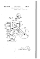
One embodiment of the apparatus will now he described by way of example with reference to the accompanying drawings, in which Figure 1 illustrates a side elevation of the combined camera and projector,
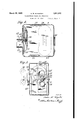
Figure 2 illustrates a side elevation partly broken away of the camera body,
Figure 3 illustrates a front elevation of the camera body,
Figure 4 is a front elevation tion of the camera body, and
Figures 5 and 6 are part plan views of the camera body.
partly in sec- Like reference numerals indicate like parts projector stand. The projector stand comprises a foot plate and aframewo k 11 bearration, etc.
ing a projector lamp 12. Near the bottom of the framework 11 isa cylindrical orifice 13 in which can be disposed an electric motor for driving the cinematograph 'gearduring projection. Above the motor and in front of the lamp is a horizontal platform 14 having a screw (not shown) by means of which the camera body is secured to the stand. I
The front wall of the camera bodyhas two rectangular apertures 15, 16 which are about {5; inch in width and 1 inch in height, and which are located one above the other and separated by a distance of about inch. The upper of these apertures 15 is to be used for taking and the lower aperture 16 forprojection.
In front of the camera body is placed a vertical brass guideway 17 in which slides a vertical plate 9 having two circular perforations and carrying two lenses 18, 19.
The upper lens 18 is for taking photographs and the lens has all the usual corrections necessary for that purpose e. g. for spherical aberration and for chromatic aber- The lower lens 19 is used for projection and its characteristic is that it allows the maximum amount of light to pass therethrough. The sliding arrangement is such that the upper lens 18 is brought into. coincidence with the upper aperture 15 for taking photographs and the lower lens 19 is moved into coincidence-with the lower aper ture 16for projection.
Unless the taking lens 18 is in coincidence with the taking aperture 15 the side cover 23 of the camera body cannot be fitted on owing to the fact that the socket 80 on the sliding lens carrier 9 will not be in a position to receive the projection 81 on the side cover 23, (see Figures 5 and 6) This ensures that the proper lens is in position when taking photographs. When the projection lens is opposite the projection aperture it will be impossible to fit the side cover on to the camera; as inthis case the socket 80 will be unable to receive the projection 81.- This. however. is no disadvantage as it will be understood that it is not necessary to exclude light from the body of the camera during projection, and hence there is no need for the side cover to be placed in position. A hinged baffle plate (not shown) may be provided on the projector stand in order to prevent extraneous light from reaching the screen or spectators. In the back Wall of the camera body is a round orifice 20 which is adjacent to the condenser of the projection lamp 12.- This orifice 20 is provided with a screw or sliding cover (not shown) which is adapted to close the orifice in a light-tight manner during taking of the film and which is removed when position by suitable locating sheaths .(not' shown) which project laterally from the septum 35 in the camera body. During-projection, on theother hand, the film 33 is on removable feed and take-Yup drums outside the camera body, the supply spool 21 being above the camera body and the take-up spool 22 being below.
In taking and in projection the film passes over the usual sprocket wheels which engage the-perforations in the film and lead it past the gate of the camera. The back of the gate has one aperture only, because no aperture is required for taking the film.
The shutter comprises two annular concentric-portions. The annular portion 70 which is used for taking, has an outer diameter of about 2 inches and an inner diameter of about inch. The annular space 4; inch in width is divided up into about 120 obturator 71 and about 240 slot 72.
The outer annulus 7 3 of the shutter, which is about inch wide, is divided by an upstanding rim 7 6 from the inner annulus, and
' and the two slots 74 are about 80 eachv giving two exposures to each picture. The reason for the provision of two slots is the usual one, viz. to avoid flicker owing to infrequent change from light to dark. The
spindle,7 7 of the shutter is positively driven.
Referring now to Figures 5 and 6 of the drawings, it will be appreciated that during taking it is essential to prevent light from penetrating into the camera through the slots 7 8 in the upper and lower surface of the camera body which, during projection permit of the passage of the film from the upper spool 21 into the camera body and from the camera body to the lower spool 22, respectively. Each side of the detachable cover 23 is provided with a catch 83, which when the cover is placed in position engages the corner of the plate 84 and forces it to the left against the action of the spring 85 and thus causes it to obstruct the slot 78. On removal of the cover 23 the plate 8d springs back into its normal position in which the slot 86 in the plate lies opposite the slot 7 8 in the camera body thus permitting the passage of the film through this slot from the supply spool 21.
During taking and projection the mechanism of the camera may be driven by hand, but preferably the camera body includes $k Work, the-winding handle pf which is shown at 90, for driving the mechanism during taking, and the projector stand contains i) use in taking the picture and the other for use in projecting it, a rotating shutter so formed that one aperture only is used during taking and the other aperture only during projection, and a sliding lens holder carry-- mg two lens systems, one for taking andthe other for projection which are adapted to be brought alternatively into coincidence with their respective apertures.
' 2. A cinematograph camera, which com prises in combination, a projector, a camera portion provided with two apertures, one for use in takingthe picture and the other for use in projecting it, a rotating shutter comprising t-wo concentric slotted sections, one adapted to co-operate with the aperture used in taking the picture and the other adapted to co-operate with the aperture used in projecting it, and a sliding lens holder carrying two lens systems, one for taking and the other for projection, which are adapted to be brought alternatively into coincidence with their respective apertures.
3. A cinematograph camera, which comprises in combination a projector, a camera portion provided with two apertures one for use in taking the picture and the other for use in projecting it, a rotating shutter so formed that one aperture only is used during taking and the other aperture only during projection, and a slidin lens holder carrying two lens systems, one or taking and the other for projection, said lens holder forming a light stop adapted to cover the projection aperture when the taking lens is in coincidence with the taking aperture, and the taking aperture when the projection lens is in coincidence with the projection aperture.
4:. Aninematograph camera, which oom-' prises in combination a projector, a camera portion provided with two apertures,one for use in taking the picture and the other for use in projecting it, a rotating shutter comprising two concentric slotted sections, one adapted to co-operate with the aperture used in taking the picture and the other adapted to co-operate with the aperture used in projecting it, and a sliding lens holder carrying two.
lens systems, one ,for taking and the other for projection, said lens holder forming a light stop adapted to cover the projection aperture when the taking lens is in coincidence with the taking aperture, and the taking aperture when the projection lens is in coincidence with the projection aperture.
5. A cinematograph camera, which comprises in combination a projector, a camera portion provided with two apertures, onefor use in taking the picture and the other for use in projecting it, a rotating shutter so formed that one aperture only is used during taking and the other aperture only during projection, and a lens holder slidably mounted in guideways on the front of the camera and carrying two lens systems, one for taking and the other for projection, which are adapted to be brought alternatively into coincidence with their respective .pertures.
6. A cinematograph camera, which com prises in combination a projector, a camera portion provided with two apertures, one or use in takingthe picture and the other for use in projecting it, a rotating shutter comprising two concentric slotted sections, one adapted to co-operate with the aperture used in taking the picture and the other adapted to co-operate with the aperture used in projecting it, and a lens holder slidably mounted in guideways on the front of the camera and carrying two lens systems, one for taking and the other for rojection, which are adapted to be brought a ternatively into coincidence with their respective apertures.
7. A cinematograph camera, which comprises in combination a projector, a camera portion provided with a loading door and having two apertures, one for use in taking the picture and the other for use in projecting it, a rotating shutter so formed that one aperture only is used during taking and the other aperture only during projection, a sliding lens holder carrying two lens systems, one
for taking and the other for rojection, which are adapted to be brought a ternatively into coincidence with their respective apertures, and a sliding stop device adapted to prevent closure of theloading door of the camera until the taking lens has been brought into coincidence with its appropriate aperture.
8. A cinematograph camera, which comprises in combination a projector, a camera portion provided with a loading door and having two apertures, one for use in taking the picture and the other for use in projecting it, a rotating shutter comprising two concentric slotted sections, one adapted to cooperate with the aperture used in taking the prises in combination a projector, a camera portion provided with two apertures, one for use in taking the picture and the other for use in projecting it, a rotating shutter com- 3 prising two concentric sections, provided with slots of different circumferential length, one adapted to co-operate with the aperture used in taking the picture, and the other adapted to co-operate with the aperture'used m in projecting it, and a iens holder slidably mounted in guideways on the front of the camera and carrying two lens systems, one for taking and the other for projection, which are adapted to be brought alternatively into 15 coincidence with their respective apertures. 10. A cinematograph camera, which comprises in combination a projector, a camera portion provided with two apertures, one for use in taking the picture and the other for 3 use in projecting it, a rotating shutter comprising two concentric sections, each having two or more slots alternating with obturator portions, one of said sections being adapted to co-oper'ate with the aperture used in tak- 25 ing the picture and the other adapted to cooperate with the aperture used in projecting it, and a lens holder siidably mounted in guideways on the front of the camera and carrying two lens systems, one for taking and the other for projection, which are adapted to, be breught alternatively into coincidence wlth their respective apertures.
' In testimony whereof I affix my signature. ARTHUR WILLIAM KINGSTON.
Applications Claiming Priority (1)
| Application Number | Priority Date | Filing Date | Title |
|---|---|---|---|
| GB1851912X | 1929-12-07 |
Publications (1)
| Publication Number | Publication Date |
|---|---|
| US1851912A true US1851912A (en) | 1932-03-29 |
Family
ID=10891994
Family Applications (1)
| Application Number | Title | Priority Date | Filing Date |
|---|---|---|---|
| US490984A Expired - Lifetime US1851912A (en) | 1929-12-07 | 1930-10-24 | Cinematograph camera and projector |
Country Status (1)
| Country | Link |
|---|---|
| US (1) | US1851912A (en) |
Cited By (3)
| Publication number | Priority date | Publication date | Assignee | Title |
|---|---|---|---|---|
| US2943535A (en) * | 1958-01-16 | 1960-07-05 | A Kip Livingston | Combined camera and projector |
| US2950647A (en) * | 1958-02-28 | 1960-08-30 | A Kip Livingston | Driving mechanism for combined moving picture camera and projector apparatus |
| US3495910A (en) * | 1964-07-14 | 1970-02-17 | Nippon Kogaku Kk | Optical system for measuring retardation and apparatus incorporating the same |
-
1930
- 1930-10-24 US US490984A patent/US1851912A/en not_active Expired - Lifetime
Cited By (3)
| Publication number | Priority date | Publication date | Assignee | Title |
|---|---|---|---|---|
| US2943535A (en) * | 1958-01-16 | 1960-07-05 | A Kip Livingston | Combined camera and projector |
| US2950647A (en) * | 1958-02-28 | 1960-08-30 | A Kip Livingston | Driving mechanism for combined moving picture camera and projector apparatus |
| US3495910A (en) * | 1964-07-14 | 1970-02-17 | Nippon Kogaku Kk | Optical system for measuring retardation and apparatus incorporating the same |
Similar Documents
| Publication | Publication Date | Title |
|---|---|---|
| US2245606A (en) | Roll-film camera | |
| US2439112A (en) | Two-film camera | |
| US2068410A (en) | Photographic camera and projector apparatus | |
| US1851912A (en) | Cinematograph camera and projector | |
| US1966261A (en) | Photographic mechanism and film magazine used therewith | |
| US2206396A (en) | Photographic reproducing apparatus | |
| US2226618A (en) | Reading and copying device | |
| US2315284A (en) | Multiple film carrying camera | |
| US1097211A (en) | Illuminating apparatus for photographic cameras. | |
| US2461405A (en) | Photographic film and screen holder | |
| US1787808A (en) | Optical system for photographic apparatus | |
| US2347749A (en) | Photographic apparatus | |
| US1748523A (en) | Photograph-enlarging apparatus | |
| US1707767A (en) | Film holder | |
| US1687069A (en) | Copying device for photographic purposes | |
| US2129001A (en) | Automatic camera | |
| US2284487A (en) | Photographic film magazine and feeding means, particularly for photorecording cameras | |
| US2053317A (en) | Photographic printing or enlarging apparatus | |
| US2081187A (en) | Photoaddressing system | |
| US1510155A (en) | Apparatus for printing moving-picture films | |
| US1977453A (en) | Means and method for photographing a large surface with short focus lenses | |
| US2112838A (en) | Photographic printing apparatus | |
| US1956947A (en) | Motion picture camera | |
| US1341492A (en) | Electric machine | |
| US1161910A (en) | Natural-color cinematography. |