US1851904A - Weatherproofing structure for windows - Google Patents
Weatherproofing structure for windows Download PDFInfo
- Publication number
- US1851904A US1851904A US448004A US44800430A US1851904A US 1851904 A US1851904 A US 1851904A US 448004 A US448004 A US 448004A US 44800430 A US44800430 A US 44800430A US 1851904 A US1851904 A US 1851904A
- Authority
- US
- United States
- Prior art keywords
- window
- weather
- windows
- rail
- weatherproofing
- Prior art date
- Legal status (The legal status is an assumption and is not a legal conclusion. Google has not performed a legal analysis and makes no representation as to the accuracy of the status listed.)
- Expired - Lifetime
Links
Images
Classifications
-
- E—FIXED CONSTRUCTIONS
- E06—DOORS, WINDOWS, SHUTTERS, OR ROLLER BLINDS IN GENERAL; LADDERS
- E06B—FIXED OR MOVABLE CLOSURES FOR OPENINGS IN BUILDINGS, VEHICLES, FENCES OR LIKE ENCLOSURES IN GENERAL, e.g. DOORS, WINDOWS, BLINDS, GATES
- E06B7/00—Special arrangements or measures in connection with doors or windows
- E06B7/16—Sealing arrangements on wings or parts co-operating with the wings
- E06B7/22—Sealing arrangements on wings or parts co-operating with the wings by means of elastic edgings, e.g. elastic rubber tubes; by means of resilient edgings, e.g. felt or plush strips, resilient metal strips
Definitions
- This invention relates to a weatherproofing structure for windows and it is an object of this invention to completely seal the window to exclude the weather especially at the corners and at the ends of the junction of the 7 upper and lower sections.
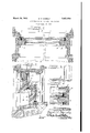
- Figure 1 is a transverse section through a window embodying this invention
- Figure 2 is an enlarged vertical sectional view through the window taken upon the line II II of Figure 1;
- Figure 3 is an enlarged fragmentary sectional view at one of the corners illustrating the continuous character of the edge weather strip taken substantially upon the line III-III of Figure 1;
- Figure 4 is an enlarged sectional view taken upon the line IVIV of Figure 2.
- a weather strip is secured upon the window frame to engage the sides, the top and bottom of the two sections that constitute the window.
- This weather strip may be continuous for each section or may be suitably jointed at certain corners.
- the reference numeral 1 represents a U-shaped strip of felt or the like partially incased in a metal sheath that is attached to the window frame and encompasses the bottom and sides of the lower window section 2 upon the inside.
- the reference numeral 3 indicates an inverted U-shaped strip of similar construction attached to the upper-half of the window frame and encompassing the upper sides and top of the upper window section 4 upon the inside.
- the stiles of the two window sections are provided with vertical grooves 5 for receiving the unencased portions of the vertically extending portions of the weather strips.
- the lower rail of the lower section and the upper rail of the upper section are provided with exterior rabbets 6 ( Figure 2) for respectively abutting against the lower and upper horizontal portions of the weather strips 1 and 3. Itwill be noted in Figure 2 that the bottoms of the grooves 5 lie inthe same plane as the bottoms 7 of the rabbets 6, and are co-planed.
- the lower rail of the upper window section' is also rabbeted as indicated at 8.
- a Weather strip 9 partly encased is secured in the rabbeted portion 8 and the unencased portion of this strip extends into a rabbet 10 ( Figure 2) formed in the upper rail of the lower window section when the sections are in closed positions.
- the casing of the weather strip 9 is preferably cut short at its ends so that the felt may project therebeyond as indicated at 11 in Figure 4 with the result that such exposed portions 11 will bear against the lower ends of the side strips of the U-shaped members 3 for effectively sealing the juncture of the two window sections.
Landscapes
- Engineering & Computer Science (AREA)
- Civil Engineering (AREA)
- Structural Engineering (AREA)
- Specific Sealing Or Ventilating Devices For Doors And Windows (AREA)
Description
March 29, 1932. D. H. HARNLY 1,851,904
WEATHERPROOFING STRUCTURE FOR WINDOWS Filed April 28, 1930 A?! Z O Patented Mar. 29, 1932 PATENT OFFICE DAVID E. HAIRNLY, OF CHICAGO, ILLINOIS WEATHERIROOFING STRUCTURE .FOR WINDOWS Application filed April 28, 1930. Serial No. 448,004.
This invention relates to a weatherproofing structure for windows and it is an object of this invention to completely seal the window to exclude the weather especially at the corners and at the ends of the junction of the 7 upper and lower sections.
The invention. comprises the novel structure and combination of parts hereinafter described and more particularly pointed out and defined in the appended claims.
In the accompanying drawings which illustrates a preferred form of this invention and in which similar reference numerals refer to similar features in the different views;
Figure 1 is a transverse section through a window embodying this invention Figure 2 is an enlarged vertical sectional view through the window taken upon the line II II of Figure 1;
Figure 3 is an enlarged fragmentary sectional view at one of the corners illustrating the continuous character of the edge weather strip taken substantially upon the line III-III of Figure 1; and
Figure 4; is an enlarged sectional view taken upon the line IVIV of Figure 2.
According to this invention, a weather strip is secured upon the window frame to engage the sides, the top and bottom of the two sections that constitute the window. This weather strip may be continuous for each section or may be suitably jointed at certain corners. The reference numeral 1 represents a U-shaped strip of felt or the like partially incased in a metal sheath that is attached to the window frame and encompasses the bottom and sides of the lower window section 2 upon the inside. The reference numeral 3 indicates an inverted U-shaped strip of similar construction attached to the upper-half of the window frame and encompassing the upper sides and top of the upper window section 4 upon the inside.
The stiles of the two window sections are provided with vertical grooves 5 for receiving the unencased portions of the vertically extending portions of the weather strips. The lower rail of the lower section and the upper rail of the upper section are provided with exterior rabbets 6 (Figure 2) for respectively abutting against the lower and upper horizontal portions of the weather strips 1 and 3. Itwill be noted in Figure 2 that the bottoms of the grooves 5 lie inthe same plane as the bottoms 7 of the rabbets 6, and are co-planed.
The lower rail of the upper window section'is also rabbeted as indicated at 8. A Weather strip 9 partly encased is secured in the rabbeted portion 8 and the unencased portion of this strip extends into a rabbet 10 (Figure 2) formed in the upper rail of the lower window section when the sections are in closed positions. The casing of the weather strip 9 is preferably cut short at its ends so that the felt may project therebeyond as indicated at 11 in Figure 4 with the result that such exposed portions 11 will bear against the lower ends of the side strips of the U-shaped members 3 for effectively sealing the juncture of the two window sections.
This juncture has never been thuswise sealed against the weather.
When the two window sections are in closed position, the juncture thereof and the borders are effectively sealed against the weather. In the past, the upper andlower corners and the ends of the juncture between the sections was never effectively sealed as herein. It will be noted that the unbroken character of the weather strips 1 and 3 at the corners and the fact that the same extends into grooved and rabbeted portions in the window sections, effectively seals the window at all points.
I am aware that many changes may be made and numerous details of construction may be varied through a wide range without departing from the principles of this invention, and I, therefore, do not purpose limit-' ing the patent granted hereon otherwise than necessitated by the prior art.
I claim as my invention:
1. The combination with a window frame, of a continuous weather strip extending upon the sides and one end thereof, a window slidably mounted in said frame and comprising a rail and stiles, said stiles having grooves for receiving said weather strip and said rail having a rabbet with its bottom in the plane of the bottom of the grooves for receiving the horizontal portion of said weather strip.
2. The combination with a window frame of a window consisting of an upper and lower sect-ion, having adjacent rails in their closed position, said rails being rabbeted, a weather strip secured in the rabbet of one rail and extending into the rabbet of the other rail, the stiles of the upper section being grooved, Weather strips upon the sides of said window frame extending into said grooves and cooperating with the first mentioned strip to exclude the weather. 7 V
3. The combination with an upper window section having a lower rail and stiles, each stile having a vertical groove, a Window frame, weather strips upon said frame extending into said grooves, a weather strip secured to said rail and abutting the lower ends of said weather strips upon the frame w en he w do ect on in i s closed PO- sit-ion.
te t mo y ereof I ha e er un su c e my nam a icag C ok Coun y Illi is,
DA ID
Priority Applications (1)
| Application Number | Priority Date | Filing Date | Title |
|---|---|---|---|
| US448004A US1851904A (en) | 1930-04-28 | 1930-04-28 | Weatherproofing structure for windows |
Applications Claiming Priority (1)
| Application Number | Priority Date | Filing Date | Title |
|---|---|---|---|
| US448004A US1851904A (en) | 1930-04-28 | 1930-04-28 | Weatherproofing structure for windows |
Publications (1)
| Publication Number | Publication Date |
|---|---|
| US1851904A true US1851904A (en) | 1932-03-29 |
Family
ID=23778634
Family Applications (1)
| Application Number | Title | Priority Date | Filing Date |
|---|---|---|---|
| US448004A Expired - Lifetime US1851904A (en) | 1930-04-28 | 1930-04-28 | Weatherproofing structure for windows |
Country Status (1)
| Country | Link |
|---|---|
| US (1) | US1851904A (en) |
Cited By (1)
| Publication number | Priority date | Publication date | Assignee | Title |
|---|---|---|---|---|
| US2607964A (en) * | 1948-03-11 | 1952-08-26 | Ventsulator Mfg Co Inc | Double sash metal frame window |
-
1930
- 1930-04-28 US US448004A patent/US1851904A/en not_active Expired - Lifetime
Cited By (1)
| Publication number | Priority date | Publication date | Assignee | Title |
|---|---|---|---|---|
| US2607964A (en) * | 1948-03-11 | 1952-08-26 | Ventsulator Mfg Co Inc | Double sash metal frame window |
Similar Documents
| Publication | Publication Date | Title |
|---|---|---|
| US2766492A (en) | Sliding sash windows | |
| US3540154A (en) | Jalousie constructions | |
| US2895182A (en) | Window structure | |
| ATE27030T1 (en) | PIVOT WINDOW. | |
| US1866882A (en) | Combination screen mounting and weather-strip for casement windows | |
| US2192063A (en) | Sliding door construction | |
| US1851904A (en) | Weatherproofing structure for windows | |
| US908394A (en) | Window. | |
| US2337633A (en) | Window construction | |
| US2120614A (en) | Metal double hung window | |
| US2593239A (en) | Storm window structure | |
| US2212221A (en) | Metal window with metal weather strips | |
| US1636365A (en) | Window flashing | |
| US1800008A (en) | Weather-strip construction for window sashes | |
| US1845206A (en) | Storm window and screen | |
| US2015448A (en) | Window sash construction | |
| US1398017A (en) | Window-screen | |
| US1691490A (en) | Window structure | |
| US1793504A (en) | Metal window and weather strip | |
| US2259008A (en) | Weather stripping | |
| US1636241A (en) | Window | |
| US1663134A (en) | Metal window construction | |
| US1686668A (en) | Weather-stripped metal window | |
| US2762088A (en) | Window assembly | |
| US1679612A (en) | Metal weather strip |