US1851897A - Ship governor - Google Patents
Ship governor Download PDFInfo
- Publication number
- US1851897A US1851897A US43440630A US1851897A US 1851897 A US1851897 A US 1851897A US 43440630 A US43440630 A US 43440630A US 1851897 A US1851897 A US 1851897A
- Authority
- US
- United States
- Prior art keywords
- valve
- ship
- roll
- governor
- engine
- Prior art date
- Legal status (The legal status is an assumption and is not a legal conclusion. Google has not performed a legal analysis and makes no representation as to the accuracy of the status listed.)
- Expired - Lifetime
Links
- XLYOFNOQVPJJNP-UHFFFAOYSA-N water Substances O XLYOFNOQVPJJNP-UHFFFAOYSA-N 0.000 description 3
- 238000010276 construction Methods 0.000 description 1
- 239000012530 fluid Substances 0.000 description 1
- 239000011295 pitch Substances 0.000 description 1
Images
Classifications
-
- B—PERFORMING OPERATIONS; TRANSPORTING
- B63—SHIPS OR OTHER WATERBORNE VESSELS; RELATED EQUIPMENT
- B63H—MARINE PROPULSION OR STEERING
- B63H21/00—Use of propulsion power plant or units on vessels
- B63H21/21—Control means for engine or transmission, specially adapted for use on marine vessels
-
- F—MECHANICAL ENGINEERING; LIGHTING; HEATING; WEAPONS; BLASTING
- F16—ENGINEERING ELEMENTS AND UNITS; GENERAL MEASURES FOR PRODUCING AND MAINTAINING EFFECTIVE FUNCTIONING OF MACHINES OR INSTALLATIONS; THERMAL INSULATION IN GENERAL
- F16K—VALVES; TAPS; COCKS; ACTUATING-FLOATS; DEVICES FOR VENTING OR AERATING
- F16K17/00—Safety valves; Equalising valves, e.g. pressure relief valves
- F16K17/36—Safety valves; Equalising valves, e.g. pressure relief valves actuated in consequence of extraneous circumstances, e.g. shock, change of position
-
- B—PERFORMING OPERATIONS; TRANSPORTING
- B63—SHIPS OR OTHER WATERBORNE VESSELS; RELATED EQUIPMENT
- B63B—SHIPS OR OTHER WATERBORNE VESSELS; EQUIPMENT FOR SHIPPING
- B63B23/00—Equipment for handling lifeboats or the like
- B63B23/30—Devices for guiding boats to water surface
- B63B23/32—Rigid guides, e.g. having arms pivoted near waterline
-
- Y—GENERAL TAGGING OF NEW TECHNOLOGICAL DEVELOPMENTS; GENERAL TAGGING OF CROSS-SECTIONAL TECHNOLOGIES SPANNING OVER SEVERAL SECTIONS OF THE IPC; TECHNICAL SUBJECTS COVERED BY FORMER USPC CROSS-REFERENCE ART COLLECTIONS [XRACs] AND DIGESTS
- Y10—TECHNICAL SUBJECTS COVERED BY FORMER USPC
- Y10T—TECHNICAL SUBJECTS COVERED BY FORMER US CLASSIFICATION
- Y10T137/00—Fluid handling
- Y10T137/0753—Control by change of position or inertia of system
- Y10T137/0923—By pendulum or swinging member
Definitions
- This invention relates to governors for preventing racing of the engine on a boat in rough seas when ⁇ the stern of the boat rises so as to lift the propeller partially out of the water.
- An object of the invention is to provide a device for this purpose which will be thoroughly reliable and simple in construction and operation.
- Figure 1 is a side elevation of the device with parts shown in section
- numeral indicates a plate which may be secured to any ixed par of the boat.
- This plate has a pair of lugs 11 for receiving a pivot rod 12 on which depending lugs 13 are pivoted.
- the lugs 13 are secured to the under side of the base 14 of a box 15.
- Adjusting screws 16 may be threaded through lugs 17 on the ends of the plate 4 and locked there so as to pivot the plate 14 and lock it in any desired position with respect to the plate 10.
- Secured to the bottom 14 of the box 15 is a plate 18 havingy upturned edges 19 to providea track for a roller 20.
- the roller is provided with grooves 21 for engaging the tracks 19 to guide the roller as it rolls forward or backward due to pitching of the ship.
- the roller 26 has a shaft 22 which may be a small rod or other shaft to which is attached a rod 23 which rod at its other end is attached to an arm 24 for controlling a valve 25.
- the end of the rod 23 may engage in one of a number of holes 26 to limit the throw of the valve arm 24.
- the extent to which the valve is opened determines the quickness with which the engine responds in change of speed.
- valve 25 may be any valve for controlling the speed of the ships engine, as for example the main throttlefvalve or abutterly valve.
- the plate 18 may be secured to the bottom 14 of the box by means of bolts 27.
- a strap 28 maybe secured at one end to the top of the plate 18 by means of one of the bolts 27 and may be bent around and rest atits other end vagainst the inner end of the box 15.
- the strap 28 serves as a stop abut- ⁇ nient for the roll 20.
- the box y is adjusted by means of the screws 16 so that the plate 14 will be level or so as to maintain the throttle 25 open when the ship is in a level position;
- the propeller relieved of its load will have a tendency to permit the engine to race.
- the roll will move forward and close the throttle to reduce the speed of the engine at this time.
- the roll 2O will be returned to its rear position, as shown in Figure 1 to open the throttle again to admit motive iiuid to the engine.
- the engine shown as a whole at numeral 29, may be any motive iiuid engine which is operated either by steam or by vacuum.
- the throttle valve 25 may be in control of any motor, as for example, instead of a fluid motor the whole valve assembly might be a rheostat operated by an arm 24 to control the speed of an electric motor.
- Control means for a marine engine comprising a valve, a valve arm operatively connected to said valve, a box adjustably positioned upon a ship, a pair of tracks secured Within said box, a roll mounted upon said tracks, a shaft extending through the center of said roll, a rod integrally connected to said shaft for maintaining said shaft at a fixed distance relative to said valve arm whereby any movement of said roll Will operate said valve, substantially as set forth.
- a ships governor comprising in combi# nation, a motor, a motor control valve having a control arm extending therefrom, a box adjustably positioned upon a ship, a pair of tracks securedvvithin' said box, a roll having grooves in its periphery mounted onsaid.
- a ships governor comprising in combination with a marine engine, a control valve f' having a control arm extending therefrom, a
- housing adj ustably mounted on a ship, tracks Y secured in said housing, a roll provided with a centered shaft adapted to be mounted on said tracks, a rod integrally connectedat one end to said shaft and adjustably connected at the other end to said control arm whereby any movement of said roll is positively transmitted to said control valve, and means for cushioning the impact of said roll Within thehox at the limit of its movement in one' direction, substantially as set forth.
Landscapes
- Engineering & Computer Science (AREA)
- General Engineering & Computer Science (AREA)
- Mechanical Engineering (AREA)
- Chemical & Material Sciences (AREA)
- Combustion & Propulsion (AREA)
- Ocean & Marine Engineering (AREA)
- Control Of Throttle Valves Provided In The Intake System Or In The Exhaust System (AREA)
Description
SHIP GOVERNOR W. C. DENNIS Filed March 8, 1950 March 29, 1932.
u .5 nn, mm. lo w m .v 1w.,
Haunt? Patented Mar. 29, 1932 UNITED STATES WELCOME CARPENTER DENNIS, OF OAKLAND, CALIFORNA SHIP GovERNoR Application led March 8, 1930. Serial No. 434,406.
This invention relates to governors for preventing racing of the engine on a boat in rough seas when `the stern of the boat rises so as to lift the propeller partially out of the water.
An object of the invention is to provide a device for this purpose which will be thoroughly reliable and simple in construction and operation. l
Referring to the accompanying-drawings, which are made a part hereof and on which similar reference characters indicate similar parts,
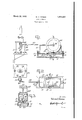
Figure 1 is a side elevation of the device with parts shown in section,
Figure 2, a plan View, and
Figure 3, a section on line 3 3 of Figure 1.
In the drawings numeral indicates a plate which may be secured to any ixed par of the boat. This plate has a pair of lugs 11 for receiving a pivot rod 12 on which depending lugs 13 are pivoted. The lugs 13 are secured to the under side of the base 14 of a box 15. Adjusting screws 16 may be threaded through lugs 17 on the ends of the plate 4 and locked there so as to pivot the plate 14 and lock it in any desired position with respect to the plate 10. Secured to the bottom 14 of the box 15 is a plate 18 havingy upturned edges 19 to providea track for a roller 20. The roller is provided with grooves 21 for engaging the tracks 19 to guide the roller as it rolls forward or backward due to pitching of the ship. The roller 26 has a shaft 22 which may be a small rod or other shaft to which is attached a rod 23 which rod at its other end is attached to an arm 24 for controlling a valve 25. The end of the rod 23 may engage in one of a number of holes 26 to limit the throw of the valve arm 24. The extent to which the valve is opened determines the quickness with which the engine responds in change of speed.
With some sizes of boats for which this device is designed, when the rod 23 is secured in four and three seconds respectively. The
In operation the box y is adjusted by means of the screws 16 so that the plate 14 will be level or so as to maintain the throttle 25 open when the ship is in a level position; When the ship pitches due to rough seas and the stern rises out of the water the propeller, relieved of its load will have a tendency to permit the engine to race. As the stern rises, however, the roll will move forward and close the throttle to reduce the speed of the engine at this time. When the stern settles back into the water again the roll 2O will be returned to its rear position, as shown in Figure 1 to open the throttle again to admit motive iiuid to the engine. The engine, shown as a whole at numeral 29, may be any motive iiuid engine which is operated either by steam or by vacuum. Obviously the throttle valve 25 may be in control of any motor, as for example, instead of a fluid motor the whole valve assembly might be a rheostat operated by an arm 24 to control the speed of an electric motor.
`It willbe obvious to those skilled in the art that various changes may be made in my device without departing from the spirit of the invention and therefore I do not limit myself to what is shown in the drawings and described in the specification, but only as indicated in the appended claims.
Having thus fully described my said invention, what I claim as new and desire to secure by Letters Patent, is z l. Control means for a marine engine comprising a valve, a valve arm operatively connected to said valve, a box adjustably positioned upon a ship, a pair of tracks secured Within said box, a roll mounted upon said tracks, a shaft extending through the center of said roll, a rod integrally connected to said shaft for maintaining said shaft at a fixed distance relative to said valve arm whereby any movement of said roll Will operate said valve, substantially as set forth.
2. A ships governor comprising in combi# nation, a motor, a motor control valve having a control arm extending therefrom, a box adjustably positioned upon a ship, a pair of tracks securedvvithin' said box, a roll having grooves in its periphery mounted onsaid.
tracks, a rod pivotally connected at one end to said control arm and at the other end to the center of said roll whereby any movement of said roll will actuate said valve, substantially as set forth.
Y 3. A ships governor comprising in combination with a marine engine, a control valve f' having a control arm extending therefrom, a
housing adj ustably mounted on a ship, tracks Y secured in said housing, a roll provided with a centered shaft adapted to be mounted on said tracks, a rod integrally connectedat one end to said shaft and adjustably connected at the other end to said control arm whereby any movement of said roll is positively transmitted to said control valve, and means for cushioning the impact of said roll Within thehox at the limit of its movement in one' direction, substantially as set forth.
In Witness whereof, I have hereunto set my hand at Oakland, California, this 28th day of February, A. D. nineteen hundred and thirty.
WELCOME CARPENTER DENNIS.
Priority Applications (1)
| Application Number | Priority Date | Filing Date | Title |
|---|---|---|---|
| US43440630 US1851897A (en) | 1930-03-08 | 1930-03-08 | Ship governor |
Applications Claiming Priority (1)
| Application Number | Priority Date | Filing Date | Title |
|---|---|---|---|
| US43440630 US1851897A (en) | 1930-03-08 | 1930-03-08 | Ship governor |
Publications (1)
| Publication Number | Publication Date |
|---|---|
| US1851897A true US1851897A (en) | 1932-03-29 |
Family
ID=23724106
Family Applications (1)
| Application Number | Title | Priority Date | Filing Date |
|---|---|---|---|
| US43440630 Expired - Lifetime US1851897A (en) | 1930-03-08 | 1930-03-08 | Ship governor |
Country Status (1)
| Country | Link |
|---|---|
| US (1) | US1851897A (en) |
Cited By (1)
| Publication number | Priority date | Publication date | Assignee | Title |
|---|---|---|---|---|
| US20080099072A1 (en) * | 2006-10-27 | 2008-05-01 | Paul Engdahl | Horizontal valve ball seat leveler |
-
1930
- 1930-03-08 US US43440630 patent/US1851897A/en not_active Expired - Lifetime
Cited By (1)
| Publication number | Priority date | Publication date | Assignee | Title |
|---|---|---|---|---|
| US20080099072A1 (en) * | 2006-10-27 | 2008-05-01 | Paul Engdahl | Horizontal valve ball seat leveler |
Similar Documents
| Publication | Publication Date | Title |
|---|---|---|
| JPS6050635B2 (en) | Trim/tilt device for marine propulsion equipment | |
| US1851897A (en) | Ship governor | |
| US2708894A (en) | Hydrofoil craft having forwardly extending water engaging and hydrofoil moving means | |
| US3085540A (en) | Automatic flip-up water rudder mechanism for sailboats and airboats | |
| US2912955A (en) | Combined cavitation plate and trim tab assembly | |
| US939878A (en) | Boat. | |
| US1226699A (en) | Boat. | |
| US3939792A (en) | Vertically liftable rudder blade | |
| US1543082A (en) | Boat-control device | |
| US1157423A (en) | Boat. | |
| US471212A (en) | Apparatus for regulating the rolling and pitching of vessels | |
| US762923A (en) | Speed-governor for ship-propellers. | |
| US1058540A (en) | Pendulum-governor for ships' engines. | |
| US1380283A (en) | Propelling mechanism for vessels | |
| US1163076A (en) | Boat. | |
| US337817A (en) | Automatic marine governor | |
| US715176A (en) | Yacht-rudder. | |
| US636271A (en) | Cut-off-valve gear for engines. | |
| US1180430A (en) | Air-thrust propeller for boats. | |
| US332212A (en) | Boat-hull | |
| US636653A (en) | Bow-facing oar attachment. | |
| US169141A (en) | Improvement in marine-engine governors | |
| US1376632A (en) | Automatic propeller-governor for boats | |
| US858320A (en) | Governor. | |
| US198053A (en) | Improvement in steering-propellers |