US1851894A - Control device for oil or gas wells - Google Patents
Control device for oil or gas wells Download PDFInfo
- Publication number
- US1851894A US1851894A US31700028A US1851894A US 1851894 A US1851894 A US 1851894A US 31700028 A US31700028 A US 31700028A US 1851894 A US1851894 A US 1851894A
- Authority
- US
- United States
- Prior art keywords
- valve
- aperture
- recess
- body portion
- secured
- Prior art date
- Legal status (The legal status is an assumption and is not a legal conclusion. Google has not performed a legal analysis and makes no representation as to the accuracy of the status listed.)
- Expired - Lifetime
Links
- 239000012530 fluid Substances 0.000 description 17
- 238000012856 packing Methods 0.000 description 3
- RTZKZFJDLAIYFH-UHFFFAOYSA-N Diethyl ether Chemical compound CCOCC RTZKZFJDLAIYFH-UHFFFAOYSA-N 0.000 description 2
- 238000010276 construction Methods 0.000 description 2
- 239000002184 metal Substances 0.000 description 2
- BWWVAEOLVKTZFQ-NTZNESFSSA-N Amdinocillin Chemical compound N([C@H]1[C@H]2SC([C@@H](N2C1=O)C(O)=O)(C)C)=CN1CCCCCC1 BWWVAEOLVKTZFQ-NTZNESFSSA-N 0.000 description 1
- 101000649938 Mus musculus Vacuolar protein sorting-associated protein 28 homolog Proteins 0.000 description 1
- 239000008186 active pharmaceutical agent Substances 0.000 description 1
- 238000007664 blowing Methods 0.000 description 1
- 239000004568 cement Substances 0.000 description 1
- 230000004048 modification Effects 0.000 description 1
- 238000012986 modification Methods 0.000 description 1
- 230000008439 repair process Effects 0.000 description 1
- 230000036346 tooth eruption Effects 0.000 description 1
- 238000003466 welding Methods 0.000 description 1
Images

Classifications
-
- E—FIXED CONSTRUCTIONS
- E21—EARTH OR ROCK DRILLING; MINING
- E21B—EARTH OR ROCK DRILLING; OBTAINING OIL, GAS, WATER, SOLUBLE OR MELTABLE MATERIALS OR A SLURRY OF MINERALS FROM WELLS
- E21B33/00—Sealing or packing boreholes or wells
- E21B33/02—Surface sealing or packing
- E21B33/03—Well heads; Setting-up thereof
- E21B33/06—Blow-out preventers, i.e. apparatus closing around a drill pipe, e.g. annular blow-out preventers
-
- E—FIXED CONSTRUCTIONS
- E21—EARTH OR ROCK DRILLING; MINING
- E21B—EARTH OR ROCK DRILLING; OBTAINING OIL, GAS, WATER, SOLUBLE OR MELTABLE MATERIALS OR A SLURRY OF MINERALS FROM WELLS
- E21B29/00—Cutting or destroying pipes, packers, plugs or wire lines, located in boreholes or wells, e.g. cutting of damaged pipes, of windows; Deforming of pipes in boreholes or wells; Reconditioning of well casings while in the ground
- E21B29/08—Cutting or deforming pipes to control fluid flow
-
- E—FIXED CONSTRUCTIONS
- E21—EARTH OR ROCK DRILLING; MINING
- E21B—EARTH OR ROCK DRILLING; OBTAINING OIL, GAS, WATER, SOLUBLE OR MELTABLE MATERIALS OR A SLURRY OF MINERALS FROM WELLS
- E21B33/00—Sealing or packing boreholes or wells
- E21B33/02—Surface sealing or packing
- E21B33/03—Well heads; Setting-up thereof
- E21B33/06—Blow-out preventers, i.e. apparatus closing around a drill pipe, e.g. annular blow-out preventers
- E21B33/061—Ram-type blow-out preventers, e.g. with pivoting rams
- E21B33/062—Ram-type blow-out preventers, e.g. with pivoting rams with sliding rams
- E21B33/063—Ram-type blow-out preventers, e.g. with pivoting rams with sliding rams for shearing drill pipes
-
- Y—GENERAL TAGGING OF NEW TECHNOLOGICAL DEVELOPMENTS; GENERAL TAGGING OF CROSS-SECTIONAL TECHNOLOGIES SPANNING OVER SEVERAL SECTIONS OF THE IPC; TECHNICAL SUBJECTS COVERED BY FORMER USPC CROSS-REFERENCE ART COLLECTIONS [XRACs] AND DIGESTS
- Y10—TECHNICAL SUBJECTS COVERED BY FORMER USPC
- Y10T—TECHNICAL SUBJECTS COVERED BY FORMER US CLASSIFICATION
- Y10T137/00—Fluid handling
- Y10T137/8376—Combined
Definitions
- This invention relates to control devices for oil or gas wells.
- the general object of the invention is to rovide an improved device for use with a blown-out well which Iis adapted to effectively shutoi the flow.
- Another object of the invention is to provide means for shutting oif a well and for directing and controlling the flow from the well after it has been shut oil.
- a further object of the invention is to provide a device of the class described including a cutting means which is adapted to cut through casing, drill tubing, sucker rod, or any other elements which may be in the well to provide a passageway for the shut oi vaive.
- Another object of the invention is to pro-l vide novel means for gripping and supporting a string of tools or sucker rod after 1t has been cut in two.
- a further object of the invention is to provide a device of the class described having an improved gate adapted to close the valve passage sothat the cutting tool may be removed for repairs.
- Another object of the invention 1s to provide a device of the class described including n means for supporting a plurality of well casings andmeans for directing the flow of fluid from the various casin
- a further object of t e invention is to provide an improved emergency blow out shutoff which is adapted to be clamped around a well casing and which includes means for out@ ting through the various casmgs andya strm of tools and means for stopping the flow of iluid in the well.
- Fig. 1 is a side elevation of myk lmproved device positioned on swell and showingthe operatinginstallation.
- Fig. 2 is a section taken on line 2-2 of Fig.
- Y Fig. 3 is an enlarged central Lvertical sec;-
- Fig. 4 is a section taken on line 4.-4 of Fig.
- 1g. 5 is a fragmentary section similar to Flg. 3 showing the shut-oil valve in a closed position.
- Fig. .6 is a vsection taken on line 6-6 of Fig. 5.
- Fig. 7 is a fragmentary section through the shut-oli' unit showing the closure gate.
- Fig. 8 is a section taken on line 8--8 of Fig. 5.
- Fig. 9 is a section taken on line 9-9 of Fig. 8.
- Fig. 10 is a central vertical section through a modified form of shut-olf valve.
- Fig. 11 is a section taken on line 11-11 of Fig 10.
- Fig. 12 is a section similar to Fig. 10 showing the shut-off valve closed, and
- Fig. 13 is a section taken on of Fig. 10.
- this device comprises a base 12, casing supporting units 14 and 15 and afshut-oif unit 16.
- the base 12 is adapted to be secured to the outer'casing 17 of the ⁇ well as by screw threaded engagement as indicated at 18 and is pref erably anchored as by bolts 19 to a cement foundation 20.
- the base includes a central aperture 21 approximately the same size as the interior of the casing 17.
- the casing supporting unit 14 is shown as removably secured to the base 12 by bolts 22 and the casing supporting unit 15 is shown as removably secured to the unit 14 by bolts 23 and the shut-oi unit 16 is shown as removably secured to the unit 15by bolts 24.
- the units 14 and 15 are similar in construction and are interchangeable and although I have shown only two of these units for Supporting casings 27 and 28, similar units may be added for each additional string of casing used in a well.
- the units 14 and 15 include a body portion 26 having a. central-aperture 29 therein which is preferably -of the same sizeas the aperture 21 in the base 12.
- For supporting casngsI provide a pair of oppositely disposed jaws 30 in each unit which are shown as positioned in opposed housings 31 secured to the body portions 26 by bolts 32 and provided with caps 33 secured thereto by bolts 34 and provided with a central screw threaded aperture 35.
- the jaws 30 For moving the jaws 30 into engagement with the casings I provide screw threaded rods 36 positioned in the threaded apertures 35 of the caps 33 and provided with a hand wheel 37. As shown in Fig. 4 the casing engaging ends of the jaws 30 are, shaped to fit the casing and are preferably provided with gripping teeth as indicated at 38 in Fig. 3.
- the upper ends of the casings 27 and 28 are each provided with an enlarged collar 40 which is adapted to engage a metal ring 41 seated on a resilient packing ring 42 which is supported on the aws 30, thus the weight of the casing causes the ring 41 to flatten the resilient packing ring and cause it to tightly engage the inner wall of the aperture 29 and the outer wall of the casing thereby providing a fluid tight seal between the casing and the supporting unit.
- Each of the casing supporting units 14 and 15 is preferably provided with an outlet 44 having a pipe 45 connected thereto for directing the flow of fluid from the interior of the casing therebelow.
- each of the pipes 45 is preferably provided with a control valve 46 and av one-way check valve 47.
- the shut-off unit 16 includes a body portion 50 having a central aperture 51 therein which is preferably of the same size as the aperture 29 in the units 14 and 15 and the aperture 21 in the base 12.
- a central aperture 51 therein which is preferably of the same size as the aperture 29 in the units 14 and 15 and the aperture 21 in the base 12.
- shut-oli' valve housing 54 Secured to an enlarged boss 52 as by bolts 53 I provide a shut-oli' valve housing 54 having a bore or recess 55 therein which communicates at one end with an aperture 56 in the body portion 16. The opposite end of the valve housing -is closed and provided with an aperture 57 which communicates with the recess 55.
- a metal seal 58 which may be secured to the body 16 as by welding or in any other suitable' manner.
- the recess 55 iscircular in cross section and a conduit plate 60 having a square conduit 61 thereon which extends up into'the recess 55 issecured to the valve housing 54 as by ⁇ bolts 62.
- the conduit 61 is preferably connected to a pipe 63 for directing the flow of fluid therefrom and as shown in Fig. 1 the pipe 63 includes a control valve 64 and may include a check valve 64.
- shut-off valve 65 Positioned in the recess 55 of the valve housing 54 I provide a shut-off valve 65 having a recess 66 therein positioned over the conduit plate 60 and a central aperture 67 having a shaft 68 positioned therein. As clearly shown in Figs. 6 and 8 the outside diameter of the shut-off valve 65 is greater than the diameter of the aperture 5l.
- the inner end of the shaft 68 has a cutting tool 69 secured thereto which is adapted to cut an aperture the same size as the diameter of the shut-off valve 65 and includes a reduced pilot cutter 70.
- a steam turbine indicated generally at 71 and connected by a pipe 72, including a throttle or control valve 72 to a steam generating boiler 73 located a suitable distance from the well.
- a gear 74 on the shaft 68 which meshes with a gear 75 of a power jack indicated generally at 76 and shown as including a hand wheel 78.
- the gear 75 of the power jack is preferably movable .into and out of engagement with the gear 74 as indicated in Fig. 1.
- the conduit plate 60 also acts as a key to prevent turning of the valve 65 when the shaft 68 is rotated.
- a screw threaded sleeve 80 surrounding the shaft 68 and secured tothe shut-oil valve 65 as by bolts 81.
- a spool 83 Surrounding the sleeve 8O and in screw threaded engagement therewith and positioned in the aperture 57 of the housing 54 I provide a spool 83 having an enlarged flange 84 adjacent its inner end and having a hand Wheel 85 secured and keyed to its outer end. It will thus be seen that upon rotation of the hand wheel 85 in one direction the spool 83 will be revolved and will cause the sleeve r8O to move towards the aperture 51 thereby moving the shut-off valve 65 and the cutter 69.
- a suitable anti-friction caring 86 For reducing the friction between the cutter 69 and the end of the shut-off valve 65 I preferably provide a suitable anti-friction caring 86.
- the aperture 56 I provide an enlarged portion 87 in the body portion50 in which is provided a circular recess 87 of the same diameter as the cutter 69 and the valve 65 and of sufficient depth to house the cutter 69, the bearing 86 and a portion of the valve 65 when the valve is closed as shown in Fig. 5.
- the enlargement 87 also includes a recess 871 of a size to house the pilot cutter 70 when the valve 65 is closed.
- a slot 88 which has a height greater than that of the aperture 56 and is closed at one end and open at the opposite end.
- a gate or valve 89 is positioned in the slot 88 and is provided with bevelled upper and lower surfaces as indicated at ⁇ 90 which are adapted to engage similarly'bevelled tapered surfaces 91 of upper andlower inserts 92, which are itted in the slot 88 as clearly shown in Fig. 7.
- Threaded set screws 93 are provided in the enlarged portion or boss 52 which are adapted to engage the up-H per insert 92 which is movable and when the gate 89 is closed are adapted to be moved downward thereby forcing the upper insert downwardly against the upper bevelled surface 90 of the gate which in conjunction with the bottom bevelled surface 90 thereof and the bevelled surface 91 ofthe lower insert will wedge the gate 89 into tight engagement with the frontwall of the slot 88 thereby tightly closing the aperture 56.
- I For gripping and Vsupporting a string of tools as indicated at 95 I provide a pa1r of opposed plungers 96 mounted in housings 97 and apertures 98 in the body portion 50.
- the housings 97 are shown as secured to the bodv portion by bolts 99v and are provided with caps 100 secured to the housings by bolts 101.
- the caps 100 include a screw threaded aperture 102 in which screw threaded pipes 103 are positioned.
- the inner ends of the plungers 96 are bevelled as at 104 and include a reduced boss 105.
- A'slip 106 is secured to the boss 105 of each of the plungers as by a rod 107.
- the rear faces of the slips are bevelled to conformto the bevel 104 of the plungers 96.
- the gripping faces of the slips 106 are shaped to conform to the shape of the string of tools 95 and are provided with gripping teeth as indicated at 108 in Fig. 8.
- I preferably provide keys 109 in the housings 97 and keyways 110 in the plungers.
- a hydraulic meansA for actuating the plungers 96 to cause them to grip the string of tools 95
- the pipes 103 communicate with the lower portionof a tank i112 having a fluid such as oil therein, and a float 1.13 which is adapted to provide a chamber above the oil.
- the upper portion ofthe tank 112 is connected by a pipe 114to the steam generating boiler 73 and includes a control valve 115 and a check valve 116 and an exs haust valve 117 is provided on the tank 1 12.
- a hand Wheel 120 is secured to each of the pipes 103 -by which the pipes 103 may be rotated to move the pistons into engagement with the string of tools 95 in case the hydraulic actuating means is out of order or the pipes 103 may be brought .into engagement with the pistons 96 to hold .them in engagement with the stringV of tools after the hydraulic means has actuated them and it is desired to relieve the hydarulic means.
- An outlet 125 is preferably provided on the body portion and. connected to a pipe 126 which is adapted to convey fluid from the unit 16 and is shown in Fig. 2 as including a control valve 127 and a check valve 128 similar to those on the pipes 45.
- the pipes 45, the pipe 63 and the pipe 126 may extend to a suitable storage reservoir (not shown).
- An inlet 130 is preferably providedon the body portion 50 and connected to a pipe 131 which includes a control valve 132 and communicate with a mud pump 133.
- the fluid passesout through the conduit 61 into the pipe 63 and may also be conveyed out through the outlet 125 and the pipe 126. If so desired mud may be pumped through the pipe 131 and through the inlet 130 into -the well.
- the cutter 70 may be backed out, the gate 89 closed and clamped in position, the valve housing 54 removed and a new cutter secured to the shaft 68 should the cutter become dullor damaged before the cutting operation-is finished.
- Figs. 10,11 and 12 I have indicated generally at 140 a modified form of my device. This modification is adapted for use as an emergency outfit on a well' which, blows out and is notprovided with my device 10.
- the device 140 includes a body portion 142 formed in two Ahalvesy and adapted to be secured together as by bolts 143 and provided with a central aperture 144.
- body portion 142 is also shown as including a lower flange 144 and an upper flange 144".
- a shutoff valve 'housing' 147 having a recess 148 therein which communicates at one end with an aperture 149 in the body portion 142.
- the opposite end of the valvehousing is closed and provided with an y aperture 150 which communicates with the recess 1 48.
- AAs clearly shown in Fig. 11l the recess 148 is circularbin cross section and a plate 152 having a conduit 153 thereon which extends up into the recess 148 is secured to the under side of the valve housing 147 as by bolts 154.
- the conduit 153 is preferably connected to 4a pipe 159 and the conduit 157 is connected to a pipe 160 for directing the flow of -uid from conduits 153 and 157.
- shut-0H valve 162 Positioned in the recess 148 of the valve housing I provide a shut-0H valve 162 having a recess 163 therein positioned around the conduit 153 and a recess 164 positioned around the conduit 157. As shown the bottom wall of the conduit 153 is spaced from the plate 152 and the upper wall of the conduit 157 is spaced from the plate 156, thus it will be seen the conduits 153 and 157 will telescope in the recesses 163 and 164 of the valve 162.
- An-aperture 165 is provided in the under side ofthe valve 162 andcommunicates with the valve recess 163 and within the valve body I provide recesses 166 which form communi- :ating passageways between the recess 163 and the recess 164.
- the outside diameter of the valve 162 is greater than the diameter of the recess 144 in the body portion 142 and includes a central aperture 168 in which a shaft 169 is positioned.
- a cuttingtool 170 is secured on the inner endof the shaft 169 and is adapted to cut an aperture the same size as the diameter of the valve 162 and includes a pilot cutter 171.
- the shaft 169 and the cutter 170 I For rotating the shaft 169 and the cutter 170 I secure a hand wheel 173 adjacent'the outer end of the shaft 169.
- the shaft 169 may be connected to a power operating means such as the steam turbine shown in conjunction with the device ⁇ 10.
- the conduits 153 and 157 also act askeys to prevent turning of the valve 162 when the shaft 169 is rotated.
- l I For feeding the cutter 170 towards the work I provide. a screw threaded sleeve 175 surrounding the shaft 169 andsecured to the valve 162 as by bolts 17 6.
- a spool 177 Positioned in the aperture 150 and in screw threaded engage ment with the sleeve 17 5 I provide a spool 177 having an enlarged flange 178 adjacent its inner end and having a hand wheel 179 sc- 'LJ' cured adjacent its outer end. It will thus be seen that upon rotation of the hand wheel 4 179 in one direction the spool 177 will be revolved and cause the sleeve 175 to move to- awards the aperture 144 thereby moving the valve 162 and the cutter 171. For reducing the friction between the cutter and the end of the shutoff valve 162 I preferably provide au anti-friction bearing 180.
- the aperture 1349 I provide an enlarged portion 181 in the body portion 142 in which is provided a circular recess 182 of the same diameter as the cutter 17 0 and the valve 162 and of sufficient depth to house the cutter, thelbearing and a portion of the valve when the valve is in a closed position as shown in Fig. 12,
- the enlargement 181 also includes a recess 183 of a size suliicient to house the pilot cutter 171.
- a slot 185 similar to the slot 88.
- This slot 185 is closed atone end and open at the opposite end like the slot 88.
- a gate 186 similar -to the gate 89 of the device 10 and shown in detail in Fig. 7 is positioned in the slot 185 and includes bevelled upper and lower edges which are adapted to engage similarly bev.- elled surfaces of upper and lower inserts 187 similar to the inserts 92 of the device 110.
- Threaded set screws 188 are provided in the enlarged portion 145 which are adapted to engage the upper insert 187 and when the gate is closed are adapted to be moved downward to thereby force the upper insert 187 downward ⁇ against the bevelled upper edge' of the gate 186 which in conjunction with the bottom bevelled edge of the gate and the. bevelled surfacepf the lower insert will wedge the gate into tight engagement with ⁇ the front wall of the slot 185 and thereby tightly close the aperture 149.
- valve housing 147 Below the valve housing 147 and at approximately 'right .angles thereto I" provide an enlarged boss portion 195 on each side of the body portion 142 and secure thereto as by bolts 196 housings 197 and 198.
- the housings 1-97 and 198 are each provided with a recess 199 and apertures 200 are provided in the body portion 142 and are adapted to align with the recesses 199.
- the outer end of the recess 199 in the housing 198 is closed and-a screw Athread-ed aperturev201 is provided inthe housing 197 which communicates 'with the recess 199 therein.
- a rod 202 which is of a smaller diameter than that of any drill rod in the well ⁇ having cutting teeth 203 at its forward end and provided with a shaft 204 at its oppolsite end.
- the shaft 204 is positioned in an externally screw threaded.
- sleeve 2,05 which' is positioned inthe threaded 'aperture 201.
- a key 205 is provided in the housing and a keyway 205 is provided in the sleeve 205 to prevent rotation of the sleeve.
- a hand wheel .206 is secured to the free end of the shaft 204 for rtatin the shaft and a hand wheel 207 is positione on the sleeve 205 and is in screw threaded engagement therewith and abuts the end of the housing 197. Upon rotaton of the hand wheel 207 1n one direction it will move the rod 202 toward the housing 198. It will be understood that instead of the hand wheels 206 and 207 power operated means ma be -provided for rotating the shaft 204 an the sle'eve 205.
- valve housing 14 and its associated parts is removed from the body portion 142 and the two halves of the body portion 142 are separated.
- the two halves of the body rtion are then placed around the outer welllocasing indicated at 190 and secured to ether with the bolts 143 thereby tightly clamping the body ortion 142 to the outer casing 190.
- the va ve housing 147 and its associated parts are then secured to the body portion 142 with the bolts 146.
- foundation may then be rovided under the bottom liange 144 and races may be provided whichextend from the upper flange 144 to the roof of the tunnel.
- the shaft 204 ' is rotated, thus rotating the rod cutting bar 202 and the hand wheel 207 ⁇ is rotated to feed the bar 202 towards the housing 198.
- the cutter is rotated and advances it cuts through the outer casin 190, the inner casings 191 and 192 and the drill tubing 193.
- part of the bar 202 will be positioned -in the recess 199 ofthe housing 198 and part in the recess 199 of the housin 197, thus it will be seen that the bar 202 wil support the inner casings 191 and 192 and the drill tubing ⁇ 193 and prevent them from dro ping down into the well.
- e cutter 170 is then rotated by the hand wheel 17 3 and fed towards the casing 190 by the hand wheel 179.
- the cutter will cut an aperture through the casin 190 of the same size as the valve 162 and wi cut similar apertures through any other inner casings such as indicated at 191 and 192 and through the strin of tools 193 until the cutter has cut throug the opposite side of the outer casing 190 and the cutter, bearing, and the end of the valve is positionedin the recess 182 as shown in Fig. 12.
- valve 162 prevents the fluid in the inner casing 192 from backing up into the other casings 190 and 191 as it would tend to do as the greatest pressure is usually in the inner casing.
- the cutter 170 may be backed into the recess 148, the gate closed, the valve housing 147 removed and a new cutter 170 secured to the shaft 169 should the cutter 17 0 become dull or damaged before the cutting o eration is finished.
- a shut-off device including a body portion having a main and a lateral aperture therein, a valve housing removably secured to said body portion, a recess in said valve housin in alignment with the lateral aperture o said body portion, a conduit in said valve housing extending into said recess, the axis of s aid conduit being parallel to the axis of said valve housing recess, a valve in said housing and a recess 1n said valve adapted to receive said conduit.
- a body portion having a bore, said body portion having an aperture communicatin with said bore, a valve housing, a recess 1n said valve housing, a valve in said recess, a cutting tool, means to rotate said cutting tool to cut an aperture to receive said valve, means-to move said valve across said bore, said valve when moved across said bore bein adapted to restrict passage of fluid throng said bore, and means on said valve coacting with means ,on said valve housing to direct fluid toone side of said valve and out of said device.
- a body portion In a shut-oil' device, a body portion, an aperture in said body portion, another aperture in said body portion at approximately right ⁇ angles to and communicatlng with. said restrict passage of fluid through said first aperture, and means on said valve coactin with means on said valve housing adapted to direct iuid from one side of said valve out of saiddevice.
- a valve housing secured to said b portion, a
- a body portion an aperture in said body portion, another aperture in said body portion communicating with said first aperture, ⁇ said body portion comprising a plurality of sections removably secured together, a valve housing secured to said body portion, a recess in said valve housing aligning with said second aperture, a valve in said recess, a cutting tool associated with said valve, said cutting tool being adapted to cut an aperture to receive said valve, said valve being adapted to restrict passage of fluid through said first aperture, and a cutting tool disposed below said valve, said last mentioned tool being adapted to pierce a casing in said well.
- a body portion an aperture in said body portion, another aperture in said body portion at approximately right angles to and communicating with said first aperture, said body portion comprising a plurality of sections removably secured together, a valve housing secured to said body portion, a recess in said valve housing aligning with said second aperture, a valve in said recess, a shaft positioned in said valve, a cutting tool secured to said shaft adjacent the end of said valve which is disposed to wards said second aperture, said cutting tool being adapted to cut an aperture to receive said valve, means to rotate said cutting tool and means to feed said cutting tool and said valve towards and across said first aperture,
- a shut-ofil device including a body portion having a main and a lateral aperture therein, a valve housing removably secured to said body portion, a recess in said valve housing in alignment with the lateral aperture of said body portion, a conduit in said valve housing extending into said recess, the axis of said conduit being parallel to the axis of said valve housing recess, a valve in said housing and a recess in said valve adapted to receive said conduit, a gate associated with said body portiomsaid gate being movable across said lateral aperture to restrict passageway therethrough.
- a shut-ofi device including a body portion having a main and a lateral aperture therein, a valve housing on said body portion, a recess in said valve housing in alignment with said lateral aperture of said body portion, a conduit in said valve housing extending into said recess, a valve in said housing and a recess in said ⁇ valve adapted to receive said conduit.
- valve when moved across said first aperture being adapted to restrict passage of Huid through said first aperture, and means on said valve coacting with means on said valve housing adapted to direct fluid from one side of said valve out of said device, a pair of opposed housings ⁇ on said body portion, a recess in each of saidhousings and apertures in said body portion aligning with said recesses.
- a rod positioned in said recess of one'of said housings, cutting teeth on one end of said rod, a reduced shaft extending from the opposite end of said rod, means to rotate said shaft and means to feed said rod towards said opposite housing.
- a shut-off device including a body portionhaving a main and alateral aperture therein, a valve housing removably secured to said body portion, a recess in said valve housing in alignment with the lateral aperture of said body portion, a conduit in said valve housing extending into said recess, the axis
Landscapes
- Life Sciences & Earth Sciences (AREA)
- Engineering & Computer Science (AREA)
- Geology (AREA)
- Mining & Mineral Resources (AREA)
- Physics & Mathematics (AREA)
- Environmental & Geological Engineering (AREA)
- Fluid Mechanics (AREA)
- General Life Sciences & Earth Sciences (AREA)
- Geochemistry & Mineralogy (AREA)
- Branch Pipes, Bends, And The Like (AREA)
Description
March 29, 1932.
A. N. CLOUGH CONTROL DEVICE FOR OIL OR GAS .WELLS Filed Nov. 3, 1928 e El uw 4 '2; los nz "4 4 Sheets-Sheet `1 A TTORNE Y.
March 29, 1932. A. N. cLouGH 1,851,894
v CONTROL DEVICE FOR OIL OR GAS WELLS Filed Nov. 3, 1928 4 Sheets-Sheet. 2
A TTORNE Y.
March 29, 1932. A. N. cLoUGH CONTROL DEVICE FOR OIL 0R GAS WELLS Fild Nov. 3. 1928 4 Sheets-Sheet aj/V. cLoL/QH.
Mmm
ATTO EY.
March '29, 1932. A. N. c :LouGH CNTROL DEVICE PVOR OIL OR GAS WELLS 4 Vsheets-sheet Filed Nov. s, 1928 INVENTOR.
fL/v. cLouH.
A TTORNEY.
Patented Mar. 29, 14932 UNITED STATES PATENT OFFICE ALFRED N. CIIA'JUGH, 0F INGLEWOOD, CALIFORNIA, ASSIGNOB 0F TWO-THIF'DS T0 FRANKLIN' H. HAMILTON AND HENRY FORNIA J'. HICKEY, BOTH 0F LOS ANGELES, CALI- coN'rnoL nevica ron on. on eas wams Application led November 9, 1923. Serial I lo. 817,000.
This invention relates to control devices for oil or gas wells.
The general object of the invention is to rovide an improved device for use with a blown-out well which Iis adapted to effectively shutoi the flow.
Another object of the invention is to provide means for shutting oif a well and for directing and controlling the flow from the well after it has been shut oil.
A further object of the invention is to provide a device of the class described including a cutting means which is adapted to cut through casing, drill tubing, sucker rod, or any other elements which may be in the well to provide a passageway for the shut oi vaive.
Another object of the invention is to pro-l vide novel means for gripping and supporting a string of tools or sucker rod after 1t has been cut in two.
A further object of the invention is to provide a device of the class described having an improved gate adapted to close the valve passage sothat the cutting tool may be removed for repairs. c
Another object of the invention 1s to provide a device of the class described including n means for supporting a plurality of well casings andmeans for directing the flow of fluid from the various casin A further object of t e invention is to provide an improved emergency blow out shutoff which is adapted to be clamped around a well casing and which includes means for out@ ting through the various casmgs andya strm of tools and means for stopping the flow of iluid in the well.
Other objects and the advantages of this invention will be apparent from the following description taken in connection with the accompanying drawings wherein:
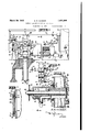
` Fig. 1 is a side elevation of myk lmproved device positioned on swell and showingthe operatinginstallation.
Fig. 2 is a section taken on line 2-2 of Fig.
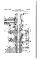
f 1 showing a fragmentary elevation of another sideof the device. Y Fig. 3 is an enlarged central Lvertical sec;-
y tion through the device.
Fig. 4 is a section taken on line 4.-4 of Fig.
3 .showing a set of casing supporting and gripplrllg Jaws.
1g. 5 is a fragmentary section similar to Flg. 3 showing the shut-oil valve in a closed position.
Fig. .6 is a vsection taken on line 6-6 of Fig. 5. v
Fig. 7 is a fragmentary section through the shut-oli' unit showing the closure gate.
Fig. 8 is a section taken on line 8--8 of Fig. 5. l
Fig. 9 is a section taken on line 9-9 of Fig. 8.
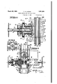
Fig. 10 is a central vertical section through a modified form of shut-olf valve.
Fig. 11 is a section taken on line 11-11 of Fig 10.
Fig. 12 is a section similar to Fig. 10 showing the shut-off valve closed, and
Fig. 13 is a section taken on of Fig. 10.
Referring to the drawings by reference characters I have indicated my improved device generally at 10. As shown this device comprises a base 12, casing supporting units 14 and 15 and afshut-oif unit 16.
The base 12 is adapted to be secured to the outer'casing 17 of the `well as by screw threaded engagement as indicated at 18 and is pref erably anchored as by bolts 19 to a cement foundation 20. The base includes a central aperture 21 approximately the same size as the interior of the casing 17.
The casing supporting unit 14 is shown as removably secured to the base 12 by bolts 22 and the casing supporting unit 15 is shown as removably secured to the unit 14 by bolts 23 and the shut-oi unit 16 is shown as removably secured to the unit 15by bolts 24.
The units 14 and 15 are similar in construction and are interchangeable and although I have shown only two of these units for Supporting casings 27 and 28, similar units may be added for each additional string of casing used in a well. As shown the units 14 and 15 include a body portion 26 having a. central-aperture 29 therein which is preferably -of the same sizeas the aperture 21 in the base 12. For supporting casngsI provide a pair of oppositely disposed jaws 30 in each unit which are shown as positioned in opposed housings 31 secured to the body portions 26 by bolts 32 and provided with caps 33 secured thereto by bolts 34 and provided with a central screw threaded aperture 35. For moving the jaws 30 into engagement with the casings I provide screw threaded rods 36 positioned in the threaded apertures 35 of the caps 33 and provided with a hand wheel 37. As shown in Fig. 4 the casing engaging ends of the jaws 30 are, shaped to fit the casing and are preferably provided with gripping teeth as indicated at 38 in Fig. 3.
The upper ends of the casings 27 and 28 are each provided with an enlarged collar 40 which is adapted to engage a metal ring 41 seated on a resilient packing ring 42 which is supported on the aws 30, thus the weight of the casing causes the ring 41 to flatten the resilient packing ring and cause it to tightly engage the inner wall of the aperture 29 and the outer wall of the casing thereby providing a fluid tight seal between the casing and the supporting unit.
Each of the casing supporting units 14 and 15 is preferably provided with an outlet 44 having a pipe 45 connected thereto for directing the flow of fluid from the interior of the casing therebelow. As shown in Fig. 2 each of the pipes 45 is preferably provided with a control valve 46 and av one-way check valve 47.
The shut-off unit 16 includes a body portion 50 having a central aperture 51 therein which is preferably of the same size as the aperture 29 in the units 14 and 15 and the aperture 21 in the base 12. Thus it will be seen that the entire device 10 is provided with a central aperture approximately the saine size as the interior of the outer well casing 17 thereby providing an unobstructed passageway through the device for handling the various inner casings.
Secured to an enlarged boss 52 as by bolts 53 I provide a shut-oli' valve housing 54 having a bore or recess 55 therein which communicates at one end with an aperture 56 in the body portion 16. The opposite end of the valve housing -is closed and provided with an aperture 57 which communicates with the recess 55. For Inormally closing the aperture 56 to prevent refuse from entering the valve housing during normal operation of the well I provide a metal seal 58 which may be secured to the body 16 as by welding or in any other suitable' manner. '4
As shown in Fig. 6 the recess 55 iscircular in cross section and a conduit plate 60 having a square conduit 61 thereon which extends up into'the recess 55 issecured to the valve housing 54 as by \bolts 62. The conduit 61 is preferably connected to a pipe 63 for directing the flow of fluid therefrom and as shown in Fig. 1 the pipe 63 includes a control valve 64 and may include a check valve 64.
Positioned in the recess 55 of the valve housing 54 I provide a shut-off valve 65 having a recess 66 therein positioned over the conduit plate 60 and a central aperture 67 having a shaft 68 positioned therein. As clearly shown in Figs. 6 and 8 the outside diameter of the shut-off valve 65 is greater than the diameter of the aperture 5l. The inner end of the shaft 68 has a cutting tool 69 secured thereto which is adapted to cut an aperture the same size as the diameter of the shut-off valve 65 and includes a reduced pilot cutter 70.
For rotating the shaft 68 and the cutter 70 I have shown in Fig. 1 a steam turbine indicated generally at 71 and connected by a pipe 72, including a throttle or control valve 72 to a steam generating boiler 73 located a suitable distance from the well.
For operating the cutter 69 by hand I provide a gear 74 on the shaft 68 which meshes with a gear 75 of a power jack indicated generally at 76 and shown as including a hand wheel 78. The gear 75 of the power jack is preferably movable .into and out of engagement with the gear 74 as indicated in Fig. 1. The conduit plate 60 also acts as a key to prevent turning of the valve 65 when the shaft 68 is rotated.
For feeding the cutter towards the Work I provide a screw threaded sleeve 80 surrounding the shaft 68 and secured tothe shut-oil valve 65 as by bolts 81. Surrounding the sleeve 8O and in screw threaded engagement therewith and positioned in the aperture 57 of the housing 54 I provide a spool 83 having an enlarged flange 84 adjacent its inner end and having a hand Wheel 85 secured and keyed to its outer end. It will thus be seen that upon rotation of the hand wheel 85 in one direction the spool 83 will be revolved and will cause the sleeve r8O to move towards the aperture 51 thereby moving the shut-off valve 65 and the cutter 69.
For reducing the friction between the cutter 69 and the end of the shut-off valve 65 I preferably provide a suitable anti-friction caring 86.
Opposite the aperture 56 I provide an enlarged portion 87 in the body portion50 in which is provided a circular recess 87 of the same diameter as the cutter 69 and the valve 65 and of sufficient depth to house the cutter 69, the bearing 86 and a portion of the valve 65 when the valve is closed as shown in Fig. 5. The enlargement 87 also includes a recess 871 of a size to house the pilot cutter 70 when the valve 65 is closed.
In the boss 52 I provide a slot 88 which has a height greater than that of the aperture 56 and is closed at one end and open at the opposite end. A gate or valve 89 is positioned in the slot 88 and is provided with bevelled upper and lower surfaces as indicated at`90 which are adapted to engage similarly'bevelled tapered surfaces 91 of upper andlower inserts 92, which are itted in the slot 88 as clearly shown in Fig. 7. Threaded set screws 93 are provided in the enlarged portion or boss 52 which are adapted to engage the up-H per insert 92 which is movable and when the gate 89 is closed are adapted to be moved downward thereby forcing the upper insert downwardly against the upper bevelled surface 90 of the gate which in conjunction with the bottom bevelled surface 90 thereof and the bevelled surface 91 ofthe lower insert will wedge the gate 89 into tight engagement with the frontwall of the slot 88 thereby tightly closing the aperture 56.
For gripping and Vsupporting a string of tools as indicated at 95 I provide a pa1r of opposed plungers 96 mounted in housings 97 and apertures 98 in the body portion 50. The housings 97 are shown as secured to the bodv portion by bolts 99v and are provided with caps 100 secured to the housings by bolts 101. The caps 100 include a screw threaded aperture 102 in which screw threaded pipes 103 are positioned. As clearly shown in Fig. 8 the inner ends of the plungers 96 are bevelled as at 104 and include a reduced boss 105.
For actuating the plungers 96 to cause them to grip the string of tools 95 I have shown a hydraulic meansA in Fig. 1. In this hydraulic actuating means the pipes 103 communicate with the lower portionof a tank i112 having a fluid such as oil therein, and a float 1.13 which is adapted to provide a chamber above the oil. The upper portion ofthe tank 112 is connected by a pipe 114to the steam generating boiler 73 and includes a control valve 115 and a check valve 116 and an exs haust valve 117 is provided on the tank 1 12. Thus it will be seen that when steam is let into I the chamber above the iioat the pressure of the steam will force the float downward and force the fluid in the tank 112 under pressure through the pipes 103 into the piston housings 97 thereby forcing the pistons 96 to move toward each other and grip the string of tools 95. Suitable packingsuch as indicated at 118 is preferably provided on the pistons 96 to prevent the fluid from passing the pistons and packing such as indicated at 119 is prefcrably secured tothe caps 100 to prevent the fluid from passing out between the pipes 103 and the caps.
A hand Wheel 120 is secured to each of the pipes 103 -by which the pipes 103 may be rotated to move the pistons into engagement with the string of tools 95 in case the hydraulic actuating means is out of order or the pipes 103 may be brought .into engagement with the pistons 96 to hold .them in engagement with the stringV of tools after the hydraulic means has actuated them and it is desired to relieve the hydarulic means.
l An outlet 125 is preferably provided on the body portion and. connected to a pipe 126 which is adapted to convey fluid from the unit 16 and is shown in Fig. 2 as including a control valve 127 and a check valve 128 similar to those on the pipes 45. The pipes 45, the pipe 63 and the pipe 126 may extend to a suitable storage reservoir (not shown).
An inlet 130 is preferably providedon the body portion 50 and connected to a pipe 131 which includes a control valve 132 and communicate with a mud pump 133.
When my improved device 10.is installed in a well as shown in Fig. 1 and the well blows out the pistons 96 are immediately actuated either by the hydraulic means or by the hand means to grip the string of tools in the welk \Then the cutter` 69. is rotated either by the steam turbine 71 or by means of the hand power jack 78 and fed towards the central aperture 51 by the hand wheel 85. The Igate 89 is normally open so that it will not interfere with the cutter 69. As the cutter is fed forward it cuts through the` seal 58 and then engages and cuts through the string of tools 95 whereupon the cutterneed not be rotated further but the cutter and shut-off valve is continued to be fed forward until the cutter, the bearing andthe end of the shut-ofi' valve is positioned in the recess 87 as shown in Fig. 5.
When the shut-oil'l valve 65is in thisposition the fluid passesout through the conduit 61 into the pipe 63 and may also be conveyed out through the outlet 125 and the pipe 126. If so desired mud may be pumped through the pipe 131 and through the inlet 130 into -the well.
By providing the gate 89 the cutter 70may be backed out, the gate 89 closed and clamped in position, the valve housing 54 removed and a new cutter secured to the shaft 68 should the cutter become dullor damaged before the cutting operation-is finished.
In Figs. 10,11 and 12 I have indicated generally at 140 a modified form of my device. This modification is adapted for use as an emergency outfit on a well' which, blows out and is notprovided with my device 10.
As shown the device 140 includes a body portion 142 formed in two Ahalvesy and adapted to be secured together as by bolts 143 and provided with a central aperture 144. The
roo
Positioned in the recess 148 of the valve housing I provide a shut-0H valve 162 having a recess 163 therein positioned around the conduit 153 and a recess 164 positioned around the conduit 157. As shown the bottom wall of the conduit 153 is spaced from the plate 152 and the upper wall of the conduit 157 is spaced from the plate 156, thus it will be seen the conduits 153 and 157 will telescope in the recesses 163 and 164 of the valve 162.
An-aperture 165 is provided in the under side ofthe valve 162 andcommunicates with the valve recess 163 and within the valve body I provide recesses 166 which form communi- :ating passageways between the recess 163 and the recess 164. 4As clearly shownin Fig..11 the outside diameter of the valve 162 is greater than the diameter of the recess 144 in the body portion 142 and includes a central aperture 168 in which a shaft 169 is positioned. j
A cuttingtool 170 is secured on the inner endof the shaft 169 and is adapted to cut an aperture the same size as the diameter of the valve 162 and includes a pilot cutter 171.
For rotating the shaft 169 and the cutter 170 I secure a hand wheel 173 adjacent'the outer end of the shaft 169.. If desired the shaft 169 may be connected to a power operating means such as the steam turbine shown in conjunction with the device`10. The conduits 153 and 157 also act askeys to prevent turning of the valve 162 when the shaft 169 is rotated. l I For feeding the cutter 170 towards the work I provide. a screw threaded sleeve 175 surrounding the shaft 169 andsecured to the valve 162 as by bolts 17 6. Positioned in the aperture 150 and in screw threaded engage ment with the sleeve 17 5 I provide a spool 177 having an enlarged flange 178 adjacent its inner end and having a hand wheel 179 sc- 'LJ' cured adjacent its outer end. It will thus be seen that upon rotation of the hand wheel 4 179 in one direction the spool 177 will be revolved and cause the sleeve 175 to move to- Awards the aperture 144 thereby moving the valve 162 and the cutter 171. For reducing the friction between the cutter and the end of the shutoff valve 162 I preferably provide au anti-friction bearing 180.
Opposite the aperture 1349 I provide an enlarged portion 181 in the body portion 142 in which is provided a circular recess 182 of the same diameter as the cutter 17 0 and the valve 162 and of sufficient depth to house the cutter, thelbearing and a portion of the valve when the valve is in a closed position as shown in Fig. 12, The enlargement 181 also includes a recess 183 of a size suliicient to house the pilot cutter 171.
In the enlarged portion 145 I provide a slot 185 ,similar to the slot 88. This slot 185 is closed atone end and open at the opposite end like the slot 88. A gate 186 similar -to the gate 89 of the device 10 and shown in detail in Fig. 7 is positioned in the slot 185 and includes bevelled upper and lower edges which are adapted to engage similarly bev.- elled surfaces of upper and lower inserts 187 similar to the inserts 92 of the device 110. Threaded set screws 188 are provided in the enlarged portion 145 which are adapted to engage the upper insert 187 and when the gate is closed are adapted to be moved downward to thereby force the upper insert 187 downward `against the bevelled upper edge' of the gate 186 which in conjunction with the bottom bevelled edge of the gate and the. bevelled surfacepf the lower insert will wedge the gate into tight engagement with` the front wall of the slot 185 and thereby tightly close the aperture 149.
Below the valve housing 147 and at approximately 'right .angles thereto I" provide an enlarged boss portion 195 on each side of the body portion 142 and secure thereto as by bolts 196 housings 197 and 198. The housings 1-97 and 198 are each provided with a recess 199 and apertures 200 are provided in the body portion 142 and are adapted to align with the recesses 199. The outer end of the recess 199 in the housing 198 is closed and-a screw Athread-ed aperturev201 is provided inthe housing 197 which communicates 'with the recess 199 therein.
Within the recess 199 of the housing 197 I provide a rod 202 which is of a smaller diameter than that of any drill rod in the well` having cutting teeth 203 at its forward end and provided with a shaft 204 at its oppolsite end. The shaft 204 is positioned in an externally screw threaded. sleeve 2,05 which' is positioned inthe threaded 'aperture 201.
A key 205 is provided in the housing and a keyway 205 is provided in the sleeve 205 to prevent rotation of the sleeve. A hand wheel .206 is secured to the free end of the shaft 204 for rtatin the shaft and a hand wheel 207 is positione on the sleeve 205 and is in screw threaded engagement therewith and abuts the end of the housing 197. Upon rotaton of the hand wheel 207 1n one direction it will move the rod 202 toward the housing 198. It will be understood that instead of the hand wheels 206 and 207 power operated means ma be -provided for rotating the shaft 204 an the sle'eve 205.
When it is desired to install my emergency device 140 on a well which has blown out it is desirable to tunnel below the surface of the ground a suitable distance'l which may be about twenty or thirty feet to ex ose the outer casing. The valve housing 14 and its associated parts is removed from the body portion 142 and the two halves of the body portion 142 are separated. The two halves of the body rtion are then placed around the outer welllocasing indicated at 190 and secured to ether with the bolts 143 thereby tightly clamping the body ortion 142 to the outer casing 190. The va ve housing 147 and its associated parts are then secured to the body portion 142 with the bolts 146. A
. foundation may then be rovided under the bottom liange 144 and races may be provided whichextend from the upper flange 144 to the roof of the tunnel.
' After the device, has been secured tothe outer casing 190 the shaft 204 'is rotated, thus rotating the rod cutting bar 202 and the hand wheel 207^ is rotated to feed the bar 202 towards the housing 198. As the cutter is rotated and advances it cuts through the outer casin 190, the inner casings 191 and 192 and the drill tubing 193. After the cutting bar 202 has gone through the casings and the drill tubing, part of the bar 202 will be positioned -in the recess 199 ofthe housing 198 and part in the recess 199 of the housin 197, thus it will be seen that the bar 202 wil support the inner casings 191 and 192 and the drill tubing` 193 and prevent them from dro ping down into the well.
e cutter 170 is then rotated by the hand wheel 17 3 and fed towards the casing 190 by the hand wheel 179. As the cutter is thus fed it will cut an aperture through the casin 190 of the same size as the valve 162 and wi cut similar apertures through any other inner casings such as indicated at 191 and 192 and through the strin of tools 193 until the cutter has cut throug the opposite side of the outer casing 190 and the cutter, bearing, and the end of the valve is positionedin the recess 182 as shown in Fig. 12.
When the shut-ofi valve 162 is in this posi tion the fluid in the inner casing 192 enters the valve recesses 163 and "164, through the aperture 165 and passes through the conduits 153 and 157 to the pipes 159 and 160 whence it tanks.
mlyebe conveyed to suitable storage ferring to Fig. 12 it will be seen that by making the inlet aperture 165 with an area approximating the area of the interior of the casing 192 the valve 162 prevents the fluid in the inner casing 192 from backing up into the other casings 190 and 191 as it would tend to do as the greatest pressure is usually in the inner casing.
By providing thegate 186 the cutter 170 may be backed into the recess 148, the gate closed, the valve housing 147 removed and a new cutter 170 secured to the shaft 169 should the cutter 17 0 become dull or damaged before the cutting o eration is finished.
From the oregoing description it will be apparent that Ihave provided a novel means for shutting oi a blowing well which is simple in construction and highly eiicient in use.
Having thus described my invention, I claim:
1. In a shut-off device including a body portion having a main and a lateral aperture therein, a valve housing removably secured to said body portion, a recess in said valve housin in alignment with the lateral aperture o said body portion, a conduit in said valve housing extending into said recess, the axis of s aid conduit being parallel to the axis of said valve housing recess, a valve in said housing and a recess 1n said valve adapted to receive said conduit.
2. In a shut-off device, a body portion having a bore, said body portion having an aperture communicatin with said bore, a valve housing, a recess 1n said valve housing, a valve in said recess, a cutting tool, means to rotate said cutting tool to cut an aperture to receive said valve, means-to move said valve across said bore, said valve when moved across said bore bein adapted to restrict passage of fluid throng said bore, and means on said valve coacting with means ,on said valve housing to direct fluid toone side of said valve and out of said device.
3. In a shut-oil' device, a body portion, an aperture in said body portion, another aperture in said body portion at approximately right` angles to and communicatlng with. said restrict passage of fluid through said first aperture, and means on said valve coactin with means on said valve housing adapted to direct iuid from one side of said valve out of saiddevice.
4. In a shut-o-devicet bod portion, a valve housing secured to said b portion, a
Vrecess in said valve housing, a valve in said recess, a shaft, a cutting tool secured to said shaft and rotatable relative to said valve, said cutting tool being adapted to cut an aperture to receive said valve, means to rotate said cutting tool, means to move said valve towards and across said aperture, said valve. when moved across said aperture being adapted to restrict passage of fluid through said aperture. y v
5. In a shut-ofi:l device for a Well, a body portion, an aperture in said body portion, another aperture in said body portion communicating with said first aperture, `said body portion comprising a plurality of sections removably secured together, a valve housing secured to said body portion, a recess in said valve housing aligning with said second aperture, a valve in said recess, a cutting tool associated with said valve, said cutting tool being adapted to cut an aperture to receive said valve, said valve being adapted to restrict passage of fluid through said first aperture, and a cutting tool disposed below said valve, said last mentioned tool being adapted to pierce a casing in said well.
6. In a shut-off device, a body portion, an aperture in said body portion, another aperture in said body portion at approximately right angles to and communicating with said first aperture, said body portion comprising a plurality of sections removably secured together, a valve housing secured to said body portion, a recess in said valve housing aligning with said second aperture, a valve in said recess, a shaft positioned in said valve, a cutting tool secured to said shaft adjacent the end of said valve which is disposed to wards said second aperture, said cutting tool being adapted to cut an aperture to receive said valve, means to rotate said cutting tool and means to feed said cutting tool and said valve towards and across said first aperture,
of said conduit being parallel to the axis of said valve housing recess, a valve in said housing and a recess in said valve adapted to receive said conduit, a shaft extending through said valve, a cutting tool secured to said shaft adjacent the face of said valve which is disposed towards said main aperture and means to rotate said shaft and said cutting tool.
8. In a shut-ofil device including a body portion having a main and a lateral aperture therein, a valve housing removably secured to said body portion, a recess in said valve housing in alignment with the lateral aperture of said body portion, a conduit in said valve housing extending into said recess, the axis of said conduit being parallel to the axis of said valve housing recess, a valve in said housing and a recess in said valve adapted to receive said conduit, a gate associated with said body portiomsaid gate being movable across said lateral aperture to restrict passageway therethrough.
9. In a shut-ofi device including a body portion having a main and a lateral aperture therein, a valve housing on said body portion, a recess in said valve housing in alignment with said lateral aperture of said body portion, a conduit in said valve housing extending into said recess, a valve in said housing and a recess in said`valve adapted to receive said conduit.
In testimony whereof, I hereunto affix my signature.
ALFRED N. CLOUGI-I.
said valve when moved across said first aperture being adapted to restrict passage of Huid through said first aperture, and means on said valve coacting with means on said valve housing adapted to direct fluid from one side of said valve out of said device, a pair of opposed housings `on said body portion, a recess in each of saidhousings and apertures in said body portion aligning with said recesses. a rod positioned in said recess of one'of said housings, cutting teeth on one end of said rod, a reduced shaft extending from the opposite end of said rod, means to rotate said shaft and means to feed said rod towards said opposite housing.
, 7. In a shut-off device including a body portionhaving a main and alateral aperture therein, a valve housing removably secured to said body portion, a recess in said valve housing in alignment with the lateral aperture of said body portion, a conduit in said valve housing extending into said recess, the axis
Priority Applications (1)
| Application Number | Priority Date | Filing Date | Title |
|---|---|---|---|
| US31700028 US1851894A (en) | 1928-11-03 | 1928-11-03 | Control device for oil or gas wells |
Applications Claiming Priority (1)
| Application Number | Priority Date | Filing Date | Title |
|---|---|---|---|
| US31700028 US1851894A (en) | 1928-11-03 | 1928-11-03 | Control device for oil or gas wells |
Publications (1)
| Publication Number | Publication Date |
|---|---|
| US1851894A true US1851894A (en) | 1932-03-29 |
Family
ID=23231673
Family Applications (1)
| Application Number | Title | Priority Date | Filing Date |
|---|---|---|---|
| US31700028 Expired - Lifetime US1851894A (en) | 1928-11-03 | 1928-11-03 | Control device for oil or gas wells |
Country Status (1)
| Country | Link |
|---|---|
| US (1) | US1851894A (en) |
Cited By (21)
| Publication number | Priority date | Publication date | Assignee | Title |
|---|---|---|---|---|
| US3379255A (en) * | 1966-07-28 | 1968-04-23 | Bowen Tools Inc | Cutoff assembly for use at wellheads |
| US3590920A (en) * | 1969-03-12 | 1971-07-06 | Shaffer Tool Works | Remote-controlled oil well pipe shear and shutoff apparatus |
| US3692107A (en) * | 1971-02-23 | 1972-09-19 | Bowen Tools Inc | Tubing hanger assembly and method of using same for hanging tubing in a well under pressure with no check valve in tubing |
| US3693715A (en) * | 1971-05-14 | 1972-09-26 | John M Brown | Apparatus for blocking fluid flow in a well casing |
| US3716068A (en) * | 1971-06-11 | 1973-02-13 | F Addison | Surface controlled blowout arrester |
| US3717202A (en) * | 1971-08-30 | 1973-02-20 | M Burrow | Remote well plugging apparatus |
| US3720260A (en) * | 1971-01-28 | 1973-03-13 | J Duck | Method and apparatus for controlling an offshore well |
| US3732924A (en) * | 1971-02-17 | 1973-05-15 | F Chelette | Apparatus for attaching to the outer of a plurality of tubular members and of cutting through, valving closed, and diverting material flow from all of the tubular members |
| US3738424A (en) * | 1971-06-14 | 1973-06-12 | Big Three Industries | Method for controlling offshore petroleum wells during blowout conditions |
| US3766979A (en) * | 1972-04-20 | 1973-10-23 | J Petrick | Well casing cutter and sealer |
| US3771601A (en) * | 1970-07-16 | 1973-11-13 | H Garrett | Well bore blocking method |
| US3870098A (en) * | 1973-08-13 | 1975-03-11 | William T Houston | Remotely controllable subterranean oil well valve |
| US4323117A (en) * | 1980-04-23 | 1982-04-06 | Laurance Pierce | Method and means for emergency shearing and sealing of well casing |
| US4476935A (en) * | 1983-03-09 | 1984-10-16 | Hydril Company | Safety valve apparatus and method |
| US5156212A (en) * | 1991-05-21 | 1992-10-20 | Bryant Thomas B | Method and system for controlling high pressure flow, such as in containment of oil and gas well fires |
| US5161617A (en) * | 1991-07-29 | 1992-11-10 | Marquip, Inc. | Directly installed shut-off and diverter valve assembly for flowing oil well with concentric casings |
| US5183364A (en) * | 1991-11-26 | 1993-02-02 | Hardwig Ronald B | Device for installing an in-line valve |
| US20070175625A1 (en) * | 2006-01-31 | 2007-08-02 | Stream-Flo Industries Ltd. | Polish Rod Clamping Device |
| US20070175626A1 (en) * | 2006-01-27 | 2007-08-02 | Stream-Flo Industries Ltd. | Wellhead Blowout Preventer With Extended Ram for Sealing Central Bore |
| US20120152561A1 (en) * | 2010-12-15 | 2012-06-21 | Vetco Gray Inc. | Emergency subsea wellhead closure devices |
| WO2016063191A1 (en) * | 2014-10-22 | 2016-04-28 | Eni S.P.A. | Safety valve for production wells |
-
1928
- 1928-11-03 US US31700028 patent/US1851894A/en not_active Expired - Lifetime
Cited By (29)
| Publication number | Priority date | Publication date | Assignee | Title |
|---|---|---|---|---|
| US3379255A (en) * | 1966-07-28 | 1968-04-23 | Bowen Tools Inc | Cutoff assembly for use at wellheads |
| US3590920A (en) * | 1969-03-12 | 1971-07-06 | Shaffer Tool Works | Remote-controlled oil well pipe shear and shutoff apparatus |
| US3771601A (en) * | 1970-07-16 | 1973-11-13 | H Garrett | Well bore blocking method |
| US3720260A (en) * | 1971-01-28 | 1973-03-13 | J Duck | Method and apparatus for controlling an offshore well |
| US3732924A (en) * | 1971-02-17 | 1973-05-15 | F Chelette | Apparatus for attaching to the outer of a plurality of tubular members and of cutting through, valving closed, and diverting material flow from all of the tubular members |
| US3692107A (en) * | 1971-02-23 | 1972-09-19 | Bowen Tools Inc | Tubing hanger assembly and method of using same for hanging tubing in a well under pressure with no check valve in tubing |
| US3693715A (en) * | 1971-05-14 | 1972-09-26 | John M Brown | Apparatus for blocking fluid flow in a well casing |
| US3716068A (en) * | 1971-06-11 | 1973-02-13 | F Addison | Surface controlled blowout arrester |
| US3738424A (en) * | 1971-06-14 | 1973-06-12 | Big Three Industries | Method for controlling offshore petroleum wells during blowout conditions |
| US3717202A (en) * | 1971-08-30 | 1973-02-20 | M Burrow | Remote well plugging apparatus |
| US3766979A (en) * | 1972-04-20 | 1973-10-23 | J Petrick | Well casing cutter and sealer |
| US3870098A (en) * | 1973-08-13 | 1975-03-11 | William T Houston | Remotely controllable subterranean oil well valve |
| US4323117A (en) * | 1980-04-23 | 1982-04-06 | Laurance Pierce | Method and means for emergency shearing and sealing of well casing |
| US4476935A (en) * | 1983-03-09 | 1984-10-16 | Hydril Company | Safety valve apparatus and method |
| US5156212A (en) * | 1991-05-21 | 1992-10-20 | Bryant Thomas B | Method and system for controlling high pressure flow, such as in containment of oil and gas well fires |
| US5161617A (en) * | 1991-07-29 | 1992-11-10 | Marquip, Inc. | Directly installed shut-off and diverter valve assembly for flowing oil well with concentric casings |
| US5183364A (en) * | 1991-11-26 | 1993-02-02 | Hardwig Ronald B | Device for installing an in-line valve |
| US20070175626A1 (en) * | 2006-01-27 | 2007-08-02 | Stream-Flo Industries Ltd. | Wellhead Blowout Preventer With Extended Ram for Sealing Central Bore |
| US7552765B2 (en) | 2006-01-27 | 2009-06-30 | Stream-Flo Industries Ltd. | Wellhead blowout preventer with extended ram for sealing central bore |
| US20070175625A1 (en) * | 2006-01-31 | 2007-08-02 | Stream-Flo Industries Ltd. | Polish Rod Clamping Device |
| US7673674B2 (en) | 2006-01-31 | 2010-03-09 | Stream-Flo Industries Ltd. | Polish rod clamping device |
| US20120152561A1 (en) * | 2010-12-15 | 2012-06-21 | Vetco Gray Inc. | Emergency subsea wellhead closure devices |
| CN102536150A (en) * | 2010-12-15 | 2012-07-04 | 韦特柯格雷公司 | Emergency subsea wellhead closure devices |
| US8622139B2 (en) * | 2010-12-15 | 2014-01-07 | Vetco Gray Inc. | Emergency subsea wellhead closure devices |
| WO2016063191A1 (en) * | 2014-10-22 | 2016-04-28 | Eni S.P.A. | Safety valve for production wells |
| CN107002478A (en) * | 2014-10-22 | 2017-08-01 | 艾尼股份公司 | Safety valve for the extraction well of hydrocarbon |
| CN107002478B (en) * | 2014-10-22 | 2019-07-02 | 艾尼股份公司 | A safety valve for an extraction well and method for closing a well |
| US10519738B2 (en) | 2014-10-22 | 2019-12-31 | Eni S.P.A. | Safety valve for production wells |
| EA034586B1 (en) * | 2014-10-22 | 2020-02-25 | Эни С.П.А. | Safety valve for production wells |
Similar Documents
| Publication | Publication Date | Title |
|---|---|---|
| US1851894A (en) | Control device for oil or gas wells | |
| US5076311A (en) | Directly installed shut-off valve assembly for flowing high pressure line | |
| US4077481A (en) | Subterranean mining apparatus | |
| US4390171A (en) | Compression spring capsule | |
| US7069988B2 (en) | Flow completion system | |
| US3698426A (en) | Mud saver valve and method | |
| US3738424A (en) | Method for controlling offshore petroleum wells during blowout conditions | |
| US3763933A (en) | Retrievable safety valve | |
| US5161617A (en) | Directly installed shut-off and diverter valve assembly for flowing oil well with concentric casings | |
| US1743338A (en) | Means for inserting valves | |
| US2150887A (en) | Method and apparatus for completing wells | |
| US3747618A (en) | Automatic shut-off valve system | |
| US3114416A (en) | Liner hanger and liner milling tool | |
| CN109736737B (en) | Method for snubbing tripping of reservoir gas drilling well | |
| EP0161261A1 (en) | Cylindrical gate valve apparatus and method. | |
| US2660248A (en) | Wellhead apparatus | |
| US1879160A (en) | Method and apparatus for extinguishing the flow of fluid in wells out of control | |
| US2571916A (en) | Pipe-line device | |
| US2241333A (en) | Well head | |
| US1455731A (en) | Automatic blow-out preventer | |
| US3202216A (en) | Submergible apparatus for underwater operations | |
| US3692107A (en) | Tubing hanger assembly and method of using same for hanging tubing in a well under pressure with no check valve in tubing | |
| US3108499A (en) | Method and apparatus for severing section of fluid pipeline therefrom | |
| US3713485A (en) | Petroleum well safety valve | |
| US1569247A (en) | Blow-out preventer |