US1851892A - Salvage unit - Google Patents
Salvage unit Download PDFInfo
- Publication number
- US1851892A US1851892A US516924A US51692431A US1851892A US 1851892 A US1851892 A US 1851892A US 516924 A US516924 A US 516924A US 51692431 A US51692431 A US 51692431A US 1851892 A US1851892 A US 1851892A
- Authority
- US
- United States
- Prior art keywords
- arms
- link
- lever
- pivotally secured
- frame
- Prior art date
- Legal status (The legal status is an assumption and is not a legal conclusion. Google has not performed a legal analysis and makes no representation as to the accuracy of the status listed.)
- Expired - Lifetime
Links
- XLYOFNOQVPJJNP-UHFFFAOYSA-N water Substances O XLYOFNOQVPJJNP-UHFFFAOYSA-N 0.000 description 9
- 230000007246 mechanism Effects 0.000 description 7
- 230000008878 coupling Effects 0.000 description 6
- 238000010168 coupling process Methods 0.000 description 6
- 238000005859 coupling reaction Methods 0.000 description 6
- 230000009471 action Effects 0.000 description 5
- 238000010276 construction Methods 0.000 description 4
- 230000008901 benefit Effects 0.000 description 2
- 238000006243 chemical reaction Methods 0.000 description 2
- 241000370092 Actiniopteris Species 0.000 description 1
- 229910000746 Structural steel Inorganic materials 0.000 description 1
- 230000000694 effects Effects 0.000 description 1
- 230000005484 gravity Effects 0.000 description 1
- 238000000034 method Methods 0.000 description 1
- 238000005086 pumping Methods 0.000 description 1
- 230000000284 resting effect Effects 0.000 description 1
- 230000000630 rising effect Effects 0.000 description 1
- 239000000126 substance Substances 0.000 description 1
Images


Classifications
-
- B—PERFORMING OPERATIONS; TRANSPORTING
- B63—SHIPS OR OTHER WATERBORNE VESSELS; RELATED EQUIPMENT
- B63C—LAUNCHING, HAULING-OUT, OR DRY-DOCKING OF VESSELS; LIFE-SAVING IN WATER; EQUIPMENT FOR DWELLING OR WORKING UNDER WATER; MEANS FOR SALVAGING OR SEARCHING FOR UNDERWATER OBJECTS
- B63C7/00—Salvaging of disabled, stranded, or sunken vessels; Salvaging of vessel parts or furnishings, e.g. of safes; Salvaging of other underwater objects
- B63C7/16—Apparatus engaging vessels or objects
- B63C7/20—Apparatus engaging vessels or objects using grabs
-
- B—PERFORMING OPERATIONS; TRANSPORTING
- B63—SHIPS OR OTHER WATERBORNE VESSELS; RELATED EQUIPMENT
- B63C—LAUNCHING, HAULING-OUT, OR DRY-DOCKING OF VESSELS; LIFE-SAVING IN WATER; EQUIPMENT FOR DWELLING OR WORKING UNDER WATER; MEANS FOR SALVAGING OR SEARCHING FOR UNDERWATER OBJECTS
- B63C7/00—Salvaging of disabled, stranded, or sunken vessels; Salvaging of vessel parts or furnishings, e.g. of safes; Salvaging of other underwater objects
- B63C7/06—Salvaging of disabled, stranded, or sunken vessels; Salvaging of vessel parts or furnishings, e.g. of safes; Salvaging of other underwater objects in which lifting action is generated in or adjacent to vessels or objects
- B63C7/08—Salvaging of disabled, stranded, or sunken vessels; Salvaging of vessel parts or furnishings, e.g. of safes; Salvaging of other underwater objects in which lifting action is generated in or adjacent to vessels or objects using rigid floats
Definitions
- the present invention relates to improvements in apparatus for raising sunken vessels, and more particularly of the type in which means are provided for gripping the object to be raised without the necessity of having divers to physically attach or secure the salvage apparatus to the sunken object, and of the type which is in itself capable of being made buoyant.
- the principal object of this invention is to provide a novel and improved salvage unit of the character mentioned, which is adapted to be floated upon the water to a position directly above the vessel to be'raised, said unit then to be submerged so that when it sets on'the sunken vessel, the latter is between the gripping elements of the apparatus which are actuated by buoyant means to grip or grab the vessel, and then theunit to be made buoyant, thus lifting itself and the vessel it holds, to the surface.
- Another object is to provide a salvage unit of the character described, including novel and improved means for gripping or grabbing the sunken vessel, which does not rely upon any agency other than the weight of the vessel to be raised for the gripping or grabbing action, after initial contact between the gripping elements and the vessel is once made by buoyant means controlled from the surface of the sea, which means after establishing the initial contact aforesaid, may thereafter be used to augment the lifting power of the main buoyant components of the unit, or else, any further action on its part capable to, be performed, may be dispensed with.
- the heavier the vessel raised the tighter is the grip of the gripping elements thereon.
- the grip may be said to independent of collaterally operated mechanism for retaining the holdon the vessel, after a small initial grip is once established by the mere contact of the gripping elements and the vessel.
- Anotherobject of this invention is to provide a salvage unit of the character mentioned. including a novel and improved means for gripping the sunken vessel to effect a pressure or squeeze grip uponopposite sub- I a stantially parallel sides of a sunken vessel, or V a grapple grip, as would be required and desirable in raising submarines or other marine structures with substantially circular crosssections.
- A'further object of the present invention is to provide an improved salvage unit of the character mentioned, includinga novel and improved gripping mechanism in which the action of each gripper shoe can be independently controlled so that an un-symmetrical section of the vessel to be raised can be securely gripped.
- a further object is to provide a salvage unit of the character described, including novel and improved pontoons which will descend in a substantially vertical direction and thereby prevent the whole unit from overturning while it is being submerged.
- Each of said pontoons is valve-less. No valve is secured to any of them as part thereof, yet each pontoon ispositive in its action and is controlled by valve mechanism located onand operated from a ship on the surface.
- Another object is to provide a salvage unit of the class described, including means comprising fins to prevent objectionable tilting of the apparatus while it moves up to or down from the surface of the water.
- a further object is to provide a salvage, unit of the character described, which can be adapted to be used for raising ships of various widths.
- a further object is to provide a salvage'unit of the character mentioned, having a low centre of gravity while afloat.
- a further object is to provide a salvage unit of novel and improved construction of the class mentioned, whichpermits marine salvage operations to be conducted and completed within a short interval of time.
- Another object of the present invention is
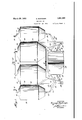
- Fig. 1 is a perspective view showing a number of salvage units, embodying the present invention, gripping asunken vessel ready to be raised. 7 I
- Fig. 2 is a frontelevation illustrating a unit of apparatus which is a preferred embodiment of this invention, showing the grippers in closed position holding a vessel.
- Fig. 3 is a plan view of such unit.
- Fig. 4 is a fragmentary front elevation of the unit, showing the grippers in their open position.
- Fig. 5 is a similar view, which however shows the grippers arranged to grab a vessel having circular cross-section.
- Fig. 6 is a vertical section the pontoons.
- Fig. 7 is a perspective View of a pontoon provided with Vertical fins.
- Fig. 8 is a section through a three-way valve showing its closed position.
- Fig. 9 is a similar section showing the valve set in position so that compressed air may through any of "pass into the pontoon.
- Fig. 10 is a similar section showing the valve 'set in position so that air may pass from the pontoon and exhaust into the at mosphere.
- a preferred embodiment of this invention which includes essentially an inverted U-shaped structural steel frame, composed of a normally horizontal member comprising the U-shaped elements 15, the arms of which are suitably connected by the braces 16, and two opposite pairs of downwardly extending spa ed members desi nated by the numerals 17 and 18.
- a gripper shoe 26 is pivotally secured to the ends of the inwardly extending arm 24 of the'bell-crank lever 23, and the link 20, by pins 27 and 28 respectively; the distance between said pins 27 and 28, being equal to .the distance between the pins 22 and 19.
- quadrilateral link gripper mechanisms are actuated by vertically inoveable pontoons 30 through the links 31.
- These pontoons 30, are slidably associated with main lifting pontoons 32, the latter of which are suitably secured to the frame elements 15,
- braces 33 serve to more rigidly secure these pontoons 32 in their fixed position on the frame of the apparatus.
- the length of the links 20, are adjusted so that the distance between the pins M1 A e) 19 and 28, shall be equal to the distance between the pins 22 and 27, when the centres of squeezed-gripped. To accomplish this, the
- length of the link 20 shall be lengthened in coupling 21, so that the distance between the pins 19 and 28, shall be greater than the distance between the pins 22 and 27, then when ,the gripper shoes 26, are brought nearer to each other by an upward motion of the pontoons 30, in respect to thepontoons 32, they will grapple or grab the vessel 40 between them, as shown in Fig. 5, instead of the squeeze-grip contact, as is the case as shown 111-]? 1g. 2. While the vessel or submarlne 40,-is being lifted, the downward reaction due to its weight will tend to further close the gripper shoes 26 towards each other, thereby obtaining a better grapple or grabbing grip.
- the action of the pontoons 30, may be dispensed with, for the weight of the vessel 29, in pulling downward, while the salvage unit is rising upward or is afloat will insure a tight grip. In fact, the heavier the vessel 29, the tighter will be this gripping.
- the lifting capacity of the pontoons 30, when bouyant may be used as auxiliaries to augment the lifting power of the main pontoons 32.
- braces 16 and 33 are demountably secured to the several parts which they serve to connect, and are to be replaced with longer or shorter braces, in accordance with the width of the vessel to be raised.
- the pontoons 30 and 32 are of the vertical type with conical portions 35 and 36, respectively top and bottom, provided as shown, with a port opening 37 in the head thereof, serving as both. inlet and outlet for the passage of air, while in the base, is an orifice 34, to permit the passage of water into and from the pontoon.
- lVhen tl'ie pontoon referring to any pontoon in the within apparatus, filled with air under pressure, it is bouyant, and no Water can enter it through the orifice 34, while when the pressure of the air in the pontoon is relieved or exhausted, water willen ter the pontoon through the orifice 34 therefor provided, and soon, enough water will have been admitted to sink the pontoon.
- a hose line 38 connects to the port 37 from air pumping machinery located on and operated from a boat (not shown) on the surface of the sea where the salvage operation is being carried out, and interposed in each hose line 38, on said boat, is a three-way valve 44 which is controlled by an operator.
- hose line 38 at its upper end connects to port A, of the said valve, while an air compressor line connects to port B, and an air exhaust pump connects to port C of said valve.
- the salvage unit In operation, the salvage unit is floated to a position directly above the vessel 29, to be i raised.
- the pontoons 30 are then allowed to fill with water, whereby they will slide to their lowest'position with respect to the pontoons 32, and the gripper shoes 26, will then be furthest apart in their opened position.
- the pontoons 32 are allowed to fill with water, by permitting the compressed air therein to escape, and the whole apparatus will sink to set on the vessel 29 in a position such that the latter should be between the gripper shoes 26.
- the pontoons 30 are made bouyant, by compressed air being allowed into them to force the water-out thru the orifices 34, and said pontoons will thereby slide upward with respect to the pontoons 32, and the gripper shoes 26 will approach each other until they gripthe vessel 29.
- the main lifting pontoons 32 are now made bouyant, and the whole unit toios gether with the vessel 29 which is within'its grip, will rise to the surface of the water, ready to be towed to drydock.
- a number of the salvage units herein described would be used as shown in Fig. 1, to furnish the required pontoon capacity for any particular salvage operation.
- the pontoons 30, may be operated either jointly or independently, and the same may be done with the main pontoons 32.
- the pontoons 30, have connected to each of them, individual hose lines 38, so that each may be independently controlled, while both pontoons 32 are arranged to be jointly operated, being that the hose line 38 feeding same, connects to both ofthe through the T'fitting 41.
- An advantage for the pontoons 32, to be independently controlled, is that if only one of them is made bouyant, the whole apparatus will tilt in one direction, which may be desirable depending upon the position of the vessel 29, resting on the bottom of the sea, while if the other pontoon previously non-bouyant is made bouyant, the whole apparatus will tilt in the opposite direction.
- This manner and method of manipulation may be used to alter the lateral position of the unit with respect to the vessel to be raised.
- An apparatus of the class described embodying a frame including a pair of downwardly extending arms, a pair of links pivotally secured at one of their respective ends to one of said arms, in spaced relation and inwardly extending towards the other of said arms, anotherpair of links pivotally secured at one of their respective ends to the second of said arms, in spaced relation and inwardly extending towards the first of said arms, a gripper shoe pivotally secured to the other ends of one of said pairs of links, the latter being in spaced relation, another gripper shoe pivotally secured to the other ends of the second pair of links, the latter being in spaced relation, said gripper shoes being adapted to receive a sunken object between them, means to move the gripper shoes relative to the frame, and means to lift the entire apparatus when the gripper shoes hold between them the object to be raised.
- An apparatus of the class described embodying a frame including a pair of downwardly extending arms, a link pivotally secured at one end to one of said arms, inwardly extending towards the other of said arms, a lever pivotally secured to the same arm above said link, said lever having its arms extending inwardly and outwardly respectively relative to said frame arm, another link pivotally secured at one end to the second frame arm, inwardly extending towards the first frame arm, another lever pivotally secured to the second frame arm above said second link, said second lever having its arms extending inwardly and outwardly respectively relative to said second frame arm, a gripper shoe pivotally secured to the other end of the first link, and to the end of the inwardly extending arm of the first lever, said points of connection being in spaced relation, a secondgripper shoe pivotally secured to the other end of the second link, and to the end of the inwardly extending arm of the second lever, said points of connection being in spaced relation, said gripper shoes being adapted to receive a sunken objectbetween them,
- An apparatus of the class described embodying a frame including a pair of downwardly extending arms, a link, comprising two bar elements and a coupling, said bars being adjustably secured in said coupling, pivotally secured at one end to one of said arms, inwardly extending towards the other of said frame arms, a lever pivotally secured to the same arm above said link, said lever having its arms extending inwardly and outwardly respectively relative to said frame arm, another link, comprising two bar elements and a coupling, said bars being adjust ably secured in said coupling, pivotally secured at one end to the second frame arm, inwardly extending towards the first frame arm, another lever pivotally secured to the second frame arm above said second link, said second lever having its arms extending inwardly and outwardly respectively relative to said second frame arm, a gripper shoe pivotally secured to the other end of the first link, and to the end of the inwardly extending arm of the first lever, said points of connection being in spaced relation, a second gripper shoe pivotally secured to the other end of the
- An apparatus of the class described embodying a frame including'a pair .of downwardly extending arms, a. link pivotally secured at one end to one of said arms, inwardly extending towards the other of said arms, a leverpivotally secured to the same arm above said link, said lever having its arms extending inwardly and outwardly-respectively relative to said frame arm, another link pivotally secured at one end to the second frame arm, inwardly extending towards the first frame arm, another lever pivotally securedto the second frame arm above said second link, said second lever having its arms extending inwardly and outwardlyrespectively relative to said second frame arm, a gripper shoe pivotally secured to the other end of the first link, and to the end of the inwardly extending arm of the first lever, said points of connection being in spaced relation, a second gripper shoe pivotally secured to the other end of thesecond link, and to the end of the inwardly extending arm of the second lever, said points of connection being in spaced relation, said gripper shoes being adapted
- An apparatus of the class described embodying a frame including a pair of downwardly extending arms, a link pivotally secured atone end to one of said arms, inwardly extending towards the other of said arms, a lever pivotally secured to the same arm above said link, said lever having its arms extending inwardly and outwardly respectively relative to said frame arm, another link pivotally secured at one end to the second frame arm, inwardly extending towards the first frame arm, another lever pivotally secured to the second frame arm above said second link, said second lever having its arms extending inwardly and outward y respectively relative to said second frame arm, a gripper shoe pivotally secured to the other end of the first link, and to the end of the inwardly extend.- ing arm of'the first lever, said points of 0011- nection being in spacedrelation, a second gripper shoe pivotallysecured to the other end of the second link, and to the end of the inwardly extending arm of the second lever, said points of connection being in spaced relation,.said: grip
- An apparatus of the class described including a pair of downwardly extending arms,a link. pivotally se cured at one end to one of said arms, inwardly extending towards the other of said arms, a
- lever pivotally secured to the same arm above said link, said lever having its arms extending inwardly and outwardly respectively relative to said frame arm, another link pivotally secured at one end to the second frame arm,
- a second gripper shoe pivotally secured to the other end of the second link, and to the end of the inwardly extending arm of the second lever, said points of connection being in spaced relation, said gripper shoes being adapted to receive a sunken object between them, a pontoon slidably associated with the frame, connected to and adapted to move the said levers, means for making the pontoon bouyant, and means for making the same non-bouyant; said pontoon when fully bouyantis adapted also to lift the entire apparatus after the gripper shoes have been shifted to positiongripping the objectto be raised.
- An apparatus of the class described embodying a frame including a pair of downwardly extending arms, a link pivotally secured at one end to one of said arms, inwardly extending towards the other of said arms, alever pivotally secured to the same arm above said link, said lever having its arms extending inwardly and outwardly respectively relative to said frame arm, another link pivotally secured at one end to the second frame arm, inwardly extending towards the first frame arm, another lever pivotally secured to the second frame arm above said second link, said second lever having its arms ex-, tending inwardly and outwardlyrespectively relative to said second frame arm, a grippershoe pivotally secured to the other end of the first link, and to the end of the inwardly extending arm of the first lever, said points of connection being in spaced relation, a second gripper shoe pivotally secured to the other end of the second link, and to the end of the inwardly extending arm of the-second lever, said points of connection being in spaced relation, said gripper shoes being adapted to receive a
- body ing a frame including a pair of down wardly extending arms, a link pivotally secured at one end to one of said arms, inwardly extending towards the other of said arms,
- a frame including a pair of downwardly extending arms, a link pivotally secured at one end to one of said arms, inwardly extending towards the other of said arms, a lever pivotally secured to the same arm above said link, said lever having its arms extending inwardly and outwardly respectively relative to said frame arm, another link pivotally secured at one end to the second frame arm, inwardly extending towards the first frame arm, another lever pivotally secured to the second frame arm above said second link, said second lever having its arms extending inwardly and outwardly respectively relative to the second frame arm, a gripper shoe pivotally secured to the other end of the first link, and to the end of the inwardly extending arm of the first lever, said points of connection being in spaced relation, a second gripper shoe pivotally secured to the other end of the second link, and to the end of the inwardly extending arm of the second lever,said points of connection being in spaced relation, said gripper shoes beingadapted to receive a sunken object between them, a pontoon slid
- 'An' apparatus of the class described embodying a frame including a pair of clownwardly extending arms, a link pivotally secured at one end to one of said arms inwardly extending towards the other of said arms, a lever pivotally secured to the same arm above said link, said lever having its arms extending inwardly and outwardly respectively relative to said frame arm, another link pivotally secured at one end to the second frame arm, inwardly extending towards the first frame arm, another lever pivotally secured to the second frame arm above said second link, said second lever having its arms extending inwardly and outwardly respectively relative to the second frame arm, a gripper shoe pivotally secured to.
- a second gripper shoe pivotally secured to the other end of the second link, and to the end of the inwardly extending arm of the second lever, said points of connection being in spaced relation, said gripper shoes being adapted to receive a sunken object between them, a pontoon slidably associated with the frame, connected to and adapted to move one of said levers, a second pontoon slidably associated with the frame, connected to and adapted to move the other of said levers, another pontoon secured to the frame, adapted to lift the entire apparatus when the gripper shoes hold between them the object to be raised, means for independently making said pontoons non-buoyant, and means for independently making said pontoons bouyant.
- An apparatus of the class described embodying a frame including a pair of downwardly extending arms, a link pivotally secured at one end to one of said arms, inwardly extending towards the other of said arms, a lever pivotally secured to the same arm above said link, said lever having its arms extendmg inwardly and outwardly respectively relative to said frame arm, another link pivotally secured at one end to the second frame arm, inwardly extending towards the first frame arm, another lever pivotally secured to the second frame arm above said second link, said second lever having its arms exinwardly extending arm of the second lever,
- said points of connection being in spaced relation, said upper shoes being adapted to receive a sun en ob ect between them, a pontoon slidably associated with the frame, con-:
- An apparatus of the class described embodying a frame including a pair of downwardly extending arms, a pair of links pivotally secured at one of their respective ends to one of said arms, in spaced relation and inwardly extending towards the other of said arms, another pair of links pivotally secured at one of their respective ends to the second of said arms, in spaced relation and inwardly extending towards the first of said arms, a gripper shoe pivotally secured to the other ends of one of said pair of links, another gripper shoe pivotally secured to the other ends of the second pair of links, said gripper shoes being adapted to receive a sunken object between them, and means to lift the apparatus when it sets onto the sunken object; the downward reaction of the sunken object being adapted to tighten the grip thereon.
Landscapes
- Engineering & Computer Science (AREA)
- Mechanical Engineering (AREA)
- Ocean & Marine Engineering (AREA)
- Load-Engaging Elements For Cranes (AREA)
Description
Filed Feb. 19. 19:51 4 Sheets-Sheet 1 ATTORNEY March 29, 1932. G. BONTEMPI 1,851,892
SALVAGE UNIT Filed Feb. 19, 1931 4 Sheets-Sheet 2 ATTORNEY Marh 29, 1932. BONTEMPl 1,851,892
SALVIAGE UNIT Filed Feb. 19, 1951 fl'Sheets-Sheet 3 26 z/ jg 1 9 25 a yu. 19
INVENTOR ATTORNEY 62a sefpe Bank/0 'Mardl 29, 19 32. a. BONTEMPI 1,851,392v
SALVAGE UNI T Filed Feb. 19, 1931 4 Sheets-Sheqt 4 INVENTOR Giuseppe Boizlegn %TORNEY Patented Mar. 29,1932' GIUSEPPE BONTEMPI, F COYTESVILLE, NEW JERSEYI SALVAGE UNIT;
Application filed February 19, 1931. Serial N0. 516,924.
The present invention relates to improvements in apparatus for raising sunken vessels, and more particularly of the type in which means are provided for gripping the object to be raised without the necessity of having divers to physically attach or secure the salvage apparatus to the sunken object, and of the type which is in itself capable of being made buoyant.
The principal object of this invention is to provide a novel and improved salvage unit of the character mentioned, which is adapted to be floated upon the water to a position directly above the vessel to be'raised, said unit then to be submerged so that when it sets on'the sunken vessel, the latter is between the gripping elements of the apparatus which are actuated by buoyant means to grip or grab the vessel, and then theunit to be made buoyant, thus lifting itself and the vessel it holds, to the surface.
Another object is to provide a salvage unit of the character described, including novel and improved means for gripping or grabbing the sunken vessel, which does not rely upon any agency other than the weight of the vessel to be raised for the gripping or grabbing action, after initial contact between the gripping elements and the vessel is once made by buoyant means controlled from the surface of the sea, which means after establishing the initial contact aforesaid, may thereafter be used to augment the lifting power of the main buoyant components of the unit, or else, any further action on its part capable to, be performed, may be dispensed with. In fact, in the within apparatus. the heavier the vessel raised, the tighter is the grip of the gripping elements thereon. The gripmay be said to independent of collaterally operated mechanism for retaining the holdon the vessel, after a small initial grip is once established by the mere contact of the gripping elements and the vessel.
Anotherobject of this invention is to provide a salvage unit of the character mentioned. including a novel and improved means for gripping the sunken vessel to effect a pressure or squeeze grip uponopposite sub- I a stantially parallel sides of a sunken vessel, or V a grapple grip, as would be required and desirable in raising submarines or other marine structures with substantially circular crosssections.
A'further object of the present invention, is to provide an improved salvage unit of the character mentioned, includinga novel and improved gripping mechanism in which the action of each gripper shoe can be independently controlled so that an un-symmetrical section of the vessel to be raised can be securely gripped.
A further object is to provide a salvage unit of the character described, including novel and improved pontoons which will descend in a substantially vertical direction and thereby prevent the whole unit from overturning while it is being submerged. Each of said pontoons is valve-less. No valve is secured to any of them as part thereof, yet each pontoon ispositive in its action and is controlled by valve mechanism located onand operated from a ship on the surface.
Another object is to provide a salvage unit of the class described, including means comprising fins to prevent objectionable tilting of the apparatus while it moves up to or down from the surface of the water.
A further object is to provide a salvage, unit of the character described, which can be adapted to be used for raising ships of various widths.
A further object is to provide a salvage'unit of the character mentioned, having a low centre of gravity while afloat.
A further object is to provide a salvage unit of novel and improved construction of the class mentioned, whichpermits marine salvage operations to be conducted and completed within a short interval of time.
Another object of the present invention, is
to provide a marine salvage unit of the character described, which is simple in construction, easy and dependable in operation, and the cost of construction of which is very reasonable in view of the nature of its capability, usefulness and adaptability.
These objects are attained with apparatus embodying in substance an inverted U frame, which when submerged, shall have the vessel to be raised between its downwardly extending arms, each of which has pivotally secured thereto, a link arrangement forming a quadrilateral unit, having as its innermost element, a gripper shoe. There will therefore be two such gripper shoes, as components of opposite quadrilateral link units, facing each other, one on each side of the vessel to be raised, and capable of being brought independently towards each other to grip the vessel, by actuating a bell-crank lever included in each link arrangement aforesaid, by a vertically moveable pontoon, preferably one for each gripper shoe link unit, which pontoon is in slidable relation with main lifting pontoons,which latter are suitably secured onto the horizontal member of the frame.
This invention is capable of numerous forms and various applications without departing from the essential features herein disclosed. It is therefore intended and desired that the embodiment shown herein be deemed illustrative and not restrictive, and that the patent shall cover whatever features of patentable novelty exist in the invention disclosed, reference being had to the appended claims rather than to the specific description herein to indicate the scope of the invention. 7
In the accompanying drawings, forming a part of this application, similar characters of reference indicate corresponding parts in all the views. 7
Fig. 1 is a perspective view showing a number of salvage units, embodying the present invention, gripping asunken vessel ready to be raised. 7 I
Fig. 2 is a frontelevation illustrating a unit of apparatus which is a preferred embodiment of this invention, showing the grippers in closed position holding a vessel.
Fig. 3 is a plan view of such unit.
, Fig. 4 is a fragmentary front elevation of the unit, showing the grippers in their open position.
Fig. 5 is a similar view, which however shows the grippers arranged to grab a vessel having circular cross-section.
Fig. 6 is a vertical section the pontoons. f
Fig. 7 is a perspective View of a pontoon provided with Vertical fins.
Fig. 8 is a section through a three-way valve showing its closed position.
Fig. 9 is a similar section showing the valve set in position so that compressed air may through any of "pass into the pontoon.
Fig. 10 is a similar section showing the valve 'set in position so that air may pass from the pontoon and exhaust into the at mosphere.
In the drawings is shown a preferred embodiment of this invention which includes essentially an inverted U-shaped structural steel frame, composed of a normally horizontal member comprising the U-shaped elements 15, the arms of which are suitably connected by the braces 16, and two opposite pairs of downwardly extending spa ed members desi nated by the numerals 17 and 18.
Because the apparatus herein concerned with, as shown, in symmetrical, and parts are in duplicate, a description of one set will be specifically given, it being understood that reference letters apply equally to both sets of mechanism.
Between the members 17 and 18, near the bottom of same, on a pin 19, is pivotally sccured one end of a link 20, the length of which is adjustable in a coupling 21. In direct vertical line, above the pin 19, on a pin, 22,
is pivotally secured a bell-crank lever at its midfulcrum, so that one of its arms 24:
is inwardly extending with respect to the frame, while the other arm 25, is outwardly extending in respect thereto, and these arms will be hereafter so designated.
A gripper shoe 26, is pivotally secured to the ends of the inwardly extending arm 24 of the'bell-crank lever 23, and the link 20, by pins 27 and 28 respectively; the distance between said pins 27 and 28, being equal to .the distance between the pins 22 and 19.
There is thus formed a quadrilateral link mechanism to be operated by a movement of the outwardly extending arms 25 of the bellcrank lever 23. l-Vhen a downward motion is imparted to the arms 25, the gripper shoes 26,- will recede from each other, while when an upward motion is imparted to said arms 25,,the gripper shoes 26 will approach each other. And so this pair of directly oppositely positioned quadrilateral link mecha nisms, constitute the gripping device of the within salvage unit. When the apparatus is submerged, it is set on to the" vessel 29 to be raised, in a position such that the latter is between the gripper shoes 26.
These quadrilateral link gripper mechanisms are actuated by vertically inoveable pontoons 30 through the links 31. These pontoons 30, are slidably associated with main lifting pontoons 32, the latter of which are suitably secured to the frame elements 15,
while braces 33 serve to more rigidly secure these pontoons 32 in their fixed position on the frame of the apparatus. An I bar 36, secured along the side of the pontoon 30, and slidable in an inwardly flanged channel 35, secured along the side of the pontoon 32, is a preferred construction to insure easy sliding.
Sunken vessels set on the bottom of the sea in a nearly upright position, and when the opposite sides thereof to be gripped are nearly parallel, it is desirable to have the gripper shoes 26 in parallel relation. To accomplish this, the length of the links 20, are adjusted so that the distance between the pins M1 A e) 19 and 28, shall be equal to the distance between the pins 22 and 27, when the centres of squeezed-gripped. To accomplish this, the
length of the link 20 shall be lengthened in coupling 21, so that the distance between the pins 19 and 28, shall be greater than the distance between the pins 22 and 27, then when ,the gripper shoes 26, are brought nearer to each other by an upward motion of the pontoons 30, in respect to thepontoons 32, they will grapple or grab the vessel 40 between them, as shown in Fig. 5, instead of the squeeze-grip contact, as is the case as shown 111-]? 1g. 2. While the vessel or submarlne 40,-is being lifted, the downward reaction due to its weight will tend to further close the gripper shoes 26 towards each other, thereby obtaining a better grapple or grabbing grip.
After initial contact of the gripper shoes 26, and the vessel 29, is once established-,the action of the pontoons 30, may be dispensed with, for the weight of the vessel 29, in pulling downward, while the salvage unit is rising upward or is afloat will insure a tight grip. In fact, the heavier the vessel 29, the tighter will be this gripping. However, the lifting capacity of the pontoons 30, when bouyant, may be used as auxiliaries to augment the lifting power of the main pontoons 32.
In the within apparatus, all braces 16 and 33, are demountably secured to the several parts which they serve to connect, and are to be replaced with longer or shorter braces, in accordance with the width of the vessel to be raised.
The pontoons used in thisapparatus, while sinking, will remain in practically an upright position. Should it be desired, however, to further insure such condition in the operation of this apparatus, along the sides of the pontoons, thereare suitably secured vertical fins 39, which tend to avoid tilting of the apparatus when descending from or emerging towards the surface of the sea.
The pontoons 30 and 32, are of the vertical type with conical portions 35 and 36, respectively top and bottom, provided as shown, with a port opening 37 in the head thereof, serving as both. inlet and outlet for the passage of air, while in the base, is an orifice 34, to permit the passage of water into and from the pontoon.
lVhen tl'ie pontoon, referring to any pontoon in the within apparatus, filled with air under pressure, it is bouyant, and no Water can enter it through the orifice 34, while when the pressure of the air in the pontoon is relieved or exhausted, water willen ter the pontoon through the orifice 34 therefor provided, and soon, enough water will have been admitted to sink the pontoon.
A hose line 38, connects to the port 37 from air pumping machinery located on and operated from a boat (not shown) on the surface of the sea where the salvage operation is being carried out, and interposed in each hose line 38, on said boat, is a three-way valve 44 which is controlled by an operator. The
In operation, the salvage unit is floated to a position directly above the vessel 29, to be i raised. The pontoons 30 are then allowed to fill with water, whereby they will slide to their lowest'position with respect to the pontoons 32, and the gripper shoes 26, will then be furthest apart in their opened position.
Slowly, the pontoons 32 are allowed to fill with water, by permitting the compressed air therein to escape, and the whole apparatus will sink to set on the vessel 29 in a position such that the latter should be between the gripper shoes 26. Now the pontoons 30 are made bouyant, by compressed air being allowed into them to force the water-out thru the orifices 34, and said pontoons will thereby slide upward with respect to the pontoons 32, and the gripper shoes 26 will approach each other until they gripthe vessel 29. The main lifting pontoons 32 are now made bouyant, and the whole unit toios gether with the vessel 29 which is within'its grip, will rise to the surface of the water, ready to be towed to drydock.
In order to provide suflicient lifting power, a number of the salvage units herein described would be used as shown in Fig. 1, to furnish the required pontoon capacity for any particular salvage operation.
The pontoons 30, may be operated either jointly or independently, and the same may be done with the main pontoons 32. shown in Fig. 2, the pontoons 30, have connected to each of them, individual hose lines 38, so that each may be independently controlled, while both pontoons 32 are arranged to be jointly operated, being that the hose line 38 feeding same, connects to both ofthe through the T'fitting 41.
An advantage for the pontoons 30, independently operated, is that when the section, at which the gripper shoes 26, are to.
metrical, the gripper shoes 26, will need to be moved into an unsymmetrical position,
which is possible only when they are individually controlled. Should said pontoons 30, be arranged to be jointly controlled, then the gripper shoes 26, will always be directly opposite each other, point for point.
An advantage for the pontoons 32, to be independently controlled, is that if only one of them is made bouyant, the whole apparatus will tilt in one direction, which may be desirable depending upon the position of the vessel 29, resting on the bottom of the sea, while if the other pontoon previously non-bouyant is made bouyant, the whole apparatus will tilt in the opposite direction. This manner and method of manipulation may be used to alter the lateral position of the unit with respect to the vessel to be raised.
Having thus described this invention, I claim 1. An apparatus of the class described, embodying a frame including a pair of downwardly extending arms, a pair of links pivotally secured at one of their respective ends to one of said arms, in spaced relation and inwardly extending towards the other of said arms, anotherpair of links pivotally secured at one of their respective ends to the second of said arms, in spaced relation and inwardly extending towards the first of said arms, a gripper shoe pivotally secured to the other ends of one of said pairs of links, the latter being in spaced relation, another gripper shoe pivotally secured to the other ends of the second pair of links, the latter being in spaced relation, said gripper shoes being adapted to receive a sunken object between them, means to move the gripper shoes relative to the frame, and means to lift the entire apparatus when the gripper shoes hold between them the object to be raised.
2. An apparatus of the class described, embodying a frame including a pair of downwardly extending arms, a link pivotally secured at one end to one of said arms, inwardly extending towards the other of said arms, a lever pivotally secured to the same arm above said link, said lever having its arms extending inwardly and outwardly respectively relative to said frame arm, another link pivotally secured at one end to the second frame arm, inwardly extending towards the first frame arm, another lever pivotally secured to the second frame arm above said second link, said second lever having its arms extending inwardly and outwardly respectively relative to said second frame arm, a gripper shoe pivotally secured to the other end of the first link, and to the end of the inwardly extending arm of the first lever, said points of connection being in spaced relation, a secondgripper shoe pivotally secured to the other end of the second link, and to the end of the inwardly extending arm of the second lever, said points of connection being in spaced relation, said gripper shoes being adapted to receive a sunken objectbetween them, means to move the outwardly extending arms of said levers, and means to lift the entire apparatus when the gripper shoes hold between them the object to be raised.
3. An apparatus of the class described, embodying a frame including a pair of downwardly extending arms, a link, comprising two bar elements and a coupling, said bars being adjustably secured in said coupling, pivotally secured at one end to one of said arms, inwardly extending towards the other of said frame arms, a lever pivotally secured to the same arm above said link, said lever having its arms extending inwardly and outwardly respectively relative to said frame arm, another link, comprising two bar elements and a coupling, said bars being adjust ably secured in said coupling, pivotally secured at one end to the second frame arm, inwardly extending towards the first frame arm, another lever pivotally secured to the second frame arm above said second link, said second lever having its arms extending inwardly and outwardly respectively relative to said second frame arm, a gripper shoe pivotally secured to the other end of the first link, and to the end of the inwardly extending arm of the first lever, said points of connection being in spaced relation, a second gripper shoe pivotally secured to the other end of the second link, and to the end of the .lever ivotally secured to the same arm above said link, said lever having its arms extending inwardly and outwardly respectively relative to said frame arm, another link pivotally secured at one end to the second. frame arm, inwardly extending towards the first frame arm, another lever pivotally secured to the second frame arm above said second link, said second lever having its arms extending inwardly and outwardly respectively relative to said second frame arm, a gripper shoe pivotally secured to the other end of i the first link, and to the end of the inwardly extending arm of the first lever, said points of connection being in spaced relation, a second gripper shoe pivotally secured. to the other end of the second link, and to the end of the inwardlyextending armofthe second lever, said points of connections being inwardly extending arms of said levers, and
means to lift the entire apparatus when the gripper shoes hold between them the object to be raised.
5. An apparatus of the class described, embodying a frame including'a pair .of downwardly extending arms, a. link pivotally secured at one end to one of said arms, inwardly extending towards the other of said arms,a leverpivotally secured to the same arm above said link, said lever having its arms extending inwardly and outwardly-respectively relative to said frame arm, another link pivotally secured at one end to the second frame arm, inwardly extending towards the first frame arm, another lever pivotally securedto the second frame arm above said second link, said second lever having its arms extending inwardly and outwardlyrespectively relative to said second frame arm, a gripper shoe pivotally secured to the other end of the first link, and to the end of the inwardly extending arm of the first lever, said points of connection being in spaced relation, a second gripper shoe pivotally secured to the other end of thesecond link, and to the end of the inwardly extending arm of the second lever, said points of connection being in spaced relation, said gripper shoes being adapted to receive a sunken object between them, means to move the outwardly extending arms of said levers, a pontoon secured to said frame, means for making the said pontoon buoyant, and means for making same non buoyant.
6. An apparatus of the class described, embodying a frame including a pair of downwardly extending arms, a link pivotally secured atone end to one of said arms, inwardly extending towards the other of said arms, a lever pivotally secured to the same arm above said link, said lever having its arms extending inwardly and outwardly respectively relative to said frame arm, another link pivotally secured at one end to the second frame arm, inwardly extending towards the first frame arm, another lever pivotally secured to the second frame arm above said second link, said second lever having its arms extending inwardly and outward y respectively relative to said second frame arm, a gripper shoe pivotally secured to the other end of the first link, and to the end of the inwardly extend.- ing arm of'the first lever, said points of 0011- nection being in spacedrelation, a second gripper shoe pivotallysecured to the other end of the second link, and to the end of the inwardly extending arm of the second lever, said points of connection being in spaced relation,.said: gripper shoes being adaptedto receive a sunken object between. them, means to move the outwardly extending arms of,
said levers, a number of pontoonssecured to the frame, means for independently making any of said pontoons non-buoyant,*and means for independently making any of said pontoons bouyant,
7. An apparatus of the class described,,embodying a frame including a pair of downwardly extending arms,a link. pivotally se cured at one end to one of said arms, inwardly extending towards the other of said arms, a
lever pivotally secured to the same arm above said link, said lever having its arms extending inwardly and outwardly respectively relative to said frame arm, another link pivotally secured at one end to the second frame arm,
inwardly extending towards the first frame ally secured to the other end of the first link;
and to the end of the inwardly extending arm of the first lever, said points of connection being in spaced relation, a second gripper shoe pivotally secured to the other end of the second link, and to the end of the inwardly extending arm of the second lever, said points of connection being in spaced relation, said gripper shoes being adapted to receive a sunken object between them, a pontoon slidably associated with the frame, connected to and adapted to move the said levers, means for making the pontoon bouyant, and means for making the same non-bouyant; said pontoon when fully bouyantis adapted also to lift the entire apparatus after the gripper shoes have been shifted to positiongripping the objectto be raised. a
8. An apparatus of the class described, embodying a frame including a pair of downwardly extending arms, a link pivotally secured at one end to one of said arms, inwardly extending towards the other of said arms, alever pivotally secured to the same arm above said link, said lever having its arms extending inwardly and outwardly respectively relative to said frame arm, another link pivotally secured at one end to the second frame arm, inwardly extending towards the first frame arm, another lever pivotally secured to the second frame arm above said second link, said second lever having its arms ex-, tending inwardly and outwardlyrespectively relative to said second frame arm, a grippershoe pivotally secured to the other end of the first link, and to the end of the inwardly extending arm of the first lever, said points of connection being in spaced relation, a second gripper shoe pivotally secured to the other end of the second link, and to the end of the inwardly extending arm of the-second lever, said points of connection being in spaced relation, said gripper shoes being adapted to receive a sunken object between them, a pontoon slidably associated with the frame, connected to and adapted to move the said levers, means for making the pontoon non-buoyant, means for making said pontoon bouyant, and means to lift the entire apparatus when the gripper shoes hold between them the object to be raised.
9. An apparatus of the class described, em-
bodying a frame including a pair of down wardly extending arms, a link pivotally secured at one end to one of said arms, inwardly extending towards the other of said arms,
'3 a lever pivotally secured to the same arm extending arm of the first lever, said points of connection being in spaced relation, a second gripper shoe pivotally secured to the other end of the second link, and to the end of the inwardly extending arm of the second lever, said points of connection being in spaced p} relation, said gripper shoes being adapted to I receive a sunken object between them, a pontoon slidably associated with the frame, connected to and adapted to move the said levers, a second pontoon secured to the frame adapted to lift the entire apparatus when the grip- 3 per shoeshold between them the object to be raised, means for independentlymaking said pontoons non-buoyant, and means for independently making said pontoons buoyant.
10. An apparatus of the class described,
embodying a frame including a pair of downwardly extending arms, a link pivotally secured at one end to one of said arms, inwardly extending towards the other of said arms, a lever pivotally secured to the same arm above said link, said lever having its arms extending inwardly and outwardly respectively relative to said frame arm, another link pivotally secured at one end to the second frame arm, inwardly extending towards the first frame arm, another lever pivotally secured to the second frame arm above said second link, said second lever having its arms extending inwardly and outwardly respectively relative to the second frame arm, a gripper shoe pivotally secured to the other end of the first link, and to the end of the inwardly extending arm of the first lever, said points of connection being in spaced relation, a second gripper shoe pivotally secured to the other end of the second link, and to the end of the inwardly extending arm of the second lever,said points of connection being in spaced relation, said gripper shoes beingadapted to receive a sunken object between them, a pontoon slidably associated with the frame, connected to and adapted to move the said levers, a number of pontoons secured to the frame, adapted to lift the entire apparatus when the gripper shoes hold between them the object to be raised, and also adapted to tilt theapparatus, means for independently making the pontoons buoyant, and means for independently making the pontoons nonbuoyant.
11. 'An' apparatus of the class described, embodying a frame including a pair of clownwardly extending arms, a link pivotally secured at one end to one of said arms inwardly extending towards the other of said arms, a lever pivotally secured to the same arm above said link, said lever having its arms extending inwardly and outwardly respectively relative to said frame arm, another link pivotally secured at one end to the second frame arm, inwardly extending towards the first frame arm, another lever pivotally secured to the second frame arm above said second link, said second lever having its arms extending inwardly and outwardly respectively relative to the second frame arm, a gripper shoe pivotally secured to. the other end of the first link, and to the end of the inwardly ex tending arm of the first lever, said points of connection being in spaced relation, a second gripper shoe pivotally secured to the other end of the second link, and to the end of the inwardly extending arm of the second lever, said points of connection being in spaced relation, said gripper shoes being adapted to receive a sunken object between them, a pontoon slidably associated with the frame, connected to and adapted to move one of said levers, a second pontoon slidably associated with the frame, connected to and adapted to move the other of said levers, another pontoon secured to the frame, adapted to lift the entire apparatus when the gripper shoes hold between them the object to be raised, means for independently making said pontoons non-buoyant, and means for independently making said pontoons bouyant.
12. An apparatus of the class described, embodying a frame including a pair of downwardly extending arms, a link pivotally secured at one end to one of said arms, inwardly extending towards the other of said arms, a lever pivotally secured to the same arm above said link, said lever having its arms extendmg inwardly and outwardly respectively relative to said frame arm, another link pivotally secured at one end to the second frame arm, inwardly extending towards the first frame arm, another lever pivotally secured to the second frame arm above said second link, said second lever having its arms exinwardly extending arm of the second lever,
said points of connection being in spaced relation, said upper shoes being adapted to receive a sun en ob ect between them, a pontoon slidably associated with the frame, con-:
nected to and adapted to move one of said levers, a second pontoon slidably associated with the frame, connected to and adapted to move the other of said levers, a number of pontoons secured to the frame, adapted to lift the entire apparatus when the gripper shoes hold between them the object to be raised, and also adapted to tilt the apparatus, means for independently making the pontoons bouyant, and means for independently making the pontoons non-bouyant.
13. An apparatus of the class described embodying a frame including a pair of downwardly extending arms, a pair of links pivotally secured at one of their respective ends to one of said arms, in spaced relation and inwardly extending towards the other of said arms, another pair of links pivotally secured at one of their respective ends to the second of said arms, in spaced relation and inwardly extending towards the first of said arms, a gripper shoe pivotally secured to the other ends of one of said pair of links, another gripper shoe pivotally secured to the other ends of the second pair of links, said gripper shoes being adapted to receive a sunken object between them, and means to lift the apparatus when it sets onto the sunken object; the downward reaction of the sunken object being adapted to tighten the grip thereon.
In witness whereof, I afiix my signature.
GIUSEPPE BONTEMPI.
Priority Applications (1)
| Application Number | Priority Date | Filing Date | Title |
|---|---|---|---|
| US516924A US1851892A (en) | 1931-02-19 | 1931-02-19 | Salvage unit |
Applications Claiming Priority (1)
| Application Number | Priority Date | Filing Date | Title |
|---|---|---|---|
| US516924A US1851892A (en) | 1931-02-19 | 1931-02-19 | Salvage unit |
Publications (1)
| Publication Number | Publication Date |
|---|---|
| US1851892A true US1851892A (en) | 1932-03-29 |
Family
ID=24057624
Family Applications (1)
| Application Number | Title | Priority Date | Filing Date |
|---|---|---|---|
| US516924A Expired - Lifetime US1851892A (en) | 1931-02-19 | 1931-02-19 | Salvage unit |
Country Status (1)
| Country | Link |
|---|---|
| US (1) | US1851892A (en) |
Cited By (2)
| Publication number | Priority date | Publication date | Assignee | Title |
|---|---|---|---|---|
| US3143096A (en) * | 1962-07-23 | 1964-08-04 | Warren H Meyer | Device for raising sunken ships |
| US3256538A (en) * | 1964-01-16 | 1966-06-21 | Vare Ind Inc | Underwater inflatable buoy |
-
1931
- 1931-02-19 US US516924A patent/US1851892A/en not_active Expired - Lifetime
Cited By (2)
| Publication number | Priority date | Publication date | Assignee | Title |
|---|---|---|---|---|
| US3143096A (en) * | 1962-07-23 | 1964-08-04 | Warren H Meyer | Device for raising sunken ships |
| US3256538A (en) * | 1964-01-16 | 1966-06-21 | Vare Ind Inc | Underwater inflatable buoy |
Similar Documents
| Publication | Publication Date | Title |
|---|---|---|
| US5002000A (en) | Automatic leveler for boat lifts | |
| US3512493A (en) | Adjustable buoyancy lift device | |
| US2398351A (en) | Marine structure | |
| US1851892A (en) | Salvage unit | |
| US4251993A (en) | Hydraulic boat lift with regulating system therefor | |
| US2508800A (en) | Equipment for salvaging submerged objects | |
| US4195948A (en) | Hydraulic boat lift with regulating system therefor | |
| US2280547A (en) | Device for raising sunken vessels | |
| US1691738A (en) | Salvaging apparatus | |
| US1912428A (en) | Salvage apparatus | |
| US3114535A (en) | Boat lifts | |
| US1740231A (en) | Rapid salvage system for submarines | |
| US1767672A (en) | Device for raising and for buoying up ships | |
| US1293899A (en) | Apparatus for raising sunken vessels. | |
| US2829615A (en) | Salvaging apparatus | |
| US1367250A (en) | Apparatus for raising sunken vessels | |
| SU1684233A1 (en) | Load-gripping arrangement | |
| US1416754A (en) | Device for raising sunken vessels | |
| US1060696A (en) | Apparatus for raising sunken wood or the like. | |
| US4357890A (en) | Stabilized, variable buoyancy apparatus | |
| US2372039A (en) | Apparatus for raising sunken vessels | |
| US1881123A (en) | Salvage unit | |
| US563565A (en) | And ebenezer m | |
| US1312473A (en) | Ship-salvaging method and apparatus | |
| US1370458A (en) | Submarine salvaging apparatus |