US1851882A - Suspension insulator - Google Patents
Suspension insulator Download PDFInfo
- Publication number
- US1851882A US1851882A US256879A US25687928A US1851882A US 1851882 A US1851882 A US 1851882A US 256879 A US256879 A US 256879A US 25687928 A US25687928 A US 25687928A US 1851882 A US1851882 A US 1851882A
- Authority
- US
- United States
- Prior art keywords
- pin
- cavity
- insulator
- head
- suspension insulator
- Prior art date
- Legal status (The legal status is an assumption and is not a legal conclusion. Google has not performed a legal analysis and makes no representation as to the accuracy of the status listed.)
- Expired - Lifetime
Links
- 239000012212 insulator Substances 0.000 title description 21
- 239000000725 suspension Substances 0.000 title description 5
- 229910052751 metal Inorganic materials 0.000 description 10
- 239000002184 metal Substances 0.000 description 10
- 239000003989 dielectric material Substances 0.000 description 4
- 239000004568 cement Substances 0.000 description 3
- 239000000463 material Substances 0.000 description 3
- 239000007787 solid Substances 0.000 description 3
- 239000011398 Portland cement Substances 0.000 description 2
- 229910001338 liquidmetal Inorganic materials 0.000 description 2
- 239000000155 melt Substances 0.000 description 2
- 238000002844 melting Methods 0.000 description 2
- 230000008018 melting Effects 0.000 description 2
- 229910000978 Pb alloy Inorganic materials 0.000 description 1
- 229910000831 Steel Inorganic materials 0.000 description 1
- 238000005452 bending Methods 0.000 description 1
- 238000005266 casting Methods 0.000 description 1
- 230000006835 compression Effects 0.000 description 1
- 238000007906 compression Methods 0.000 description 1
- 239000007788 liquid Substances 0.000 description 1
- 150000002739 metals Chemical class 0.000 description 1
- 230000004048 modification Effects 0.000 description 1
- 238000012986 modification Methods 0.000 description 1
- 229910052573 porcelain Inorganic materials 0.000 description 1
- 238000009877 rendering Methods 0.000 description 1
- 230000000717 retained effect Effects 0.000 description 1
- 239000010959 steel Substances 0.000 description 1
- 238000004804 winding Methods 0.000 description 1
Images

Classifications
-
- H—ELECTRICITY
- H01—ELECTRIC ELEMENTS
- H01B—CABLES; CONDUCTORS; INSULATORS; SELECTION OF MATERIALS FOR THEIR CONDUCTIVE, INSULATING OR DIELECTRIC PROPERTIES
- H01B17/00—Insulators or insulating bodies characterised by their form
- H01B17/02—Suspension insulators; Strain insulators
Definitions
- This invention concerns improvements in or relating to suspension insulators and to the manner of securing the insulator pins therein.
- One object of my invention is an insulator in which the pin is retained within the cavity even in case of a melting of the metal filling.
- Another object of my invention is an insulator in which the pin is secured by means of an annular member which is, on the one hand, sufiiciently rigid to serve as a holder for the pin and yet, on the other hand, sufliciently capable of being deformed to permit its introduction into the insulator cavity.
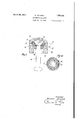
- Fig. 1 shows an axial section through a part of a suspension insulator provided with my invention, the pin being shown in elevation;
- Fig. 2 the plan view of the pin and the coordinated elements
- FIGs. 3 and 4 views similar to Figs. 1 and 2-, of a modification;
- Figs. 5 and 6 illustrate a securing plate Figs. 7 and 8 a securing ring;
- Figs. 9 and 10 another securing device.
- the insulator ranged on the pin K in such a manner that it bears from below against the pin head K Due to its springy and resilient nature it may be introduced through the constricted throat H and, when it has entered the enlarged pin cavity 0, returns again to its natural form.
- a securing device such as a washer S preferably provided with a slit, is placed over the pin stem to keep the annular member F in position.
- the washer may be pressed from below against the spring ring F so that it bears tightly against the said ring and presses the latter in turn tightly against the lower surface of the pin head K
- the washer S and the spring ring F are secured in this position by placing a split pin Sp (Fig. 9) or a spring ring B (Fig.
- the annular member In order to prevent the annular member F axial pull is exerted on the pin K, the annular member is so constructed or coordinated with the pin that it is incompressible in radial direction. This object may be achieved in various ways without rendering-the ring incapable of being deformed for the purpose of introduction into the cavity.
- annular wire spiral is intended to define a helical coil being so bent that its axis forms a circle.
- FIG. 3 Another way consists in fillingthe interior of the spiral with rigid bodies.
- a plurality of rigid bodies such as balls U of steel or other strong material, are arran ed in the interior of this spring ring F, it eing preferable to provide as many as can be filled in.
- the introduction is best efiected before the ends of thecoil forming, the ring are soldered together but may also be carried outwith the aid of a filling opening produced by bending apart two adjacent turns of the coil. 4
- An electric insulator comprising an in- "poured into said cavity .to fill the sulator body provided with an inwardly flaring cavity, a headed pin inserted therein, an annular wire spiral inserted between said pin and the wall of said cavity, rigid bodies in the interior of said wire spiral, securing means attached to said pin to keep said spiral in position thereon, and a filling poured into said cavity to fill the free space therein.
- An electric insulator comprisingan insulator body provided with a pin cavity having an inwardly flaring wall, a one-piece pin 7 entirely of hard metal having an enlarged the head and not extending therebelow, and
- An electric insulator comprising an insulator body provided with a pin cavity having an inwardly flaring wall, a one-piece pin entirely "of hard metal having an enlarged downwardly and inwardly tapering head inserted in said cavity, and an annular wire coil of circular cross-section inserted between said ,wall and the head of the pin, said annular wire coil when in inserted position bearing with its inner circumference against the head and not extending therebelow, securing means attached to the pin to keep said coil in contact with'the pin head, and a filling free space therein.
- An electric insulator comprising an insulator body provided with a pin cavity having an inwardly flaring wall, a one-piece pin entirely of hard metal having an enlarged downwardly and inwardly tapering head inserted in said cavity, an annular wire coil of ture. WILLIAM WEICKER.
Landscapes
- Insulators (AREA)
Description
W. WEECKER SUSPENSION INSULATOR Filed Feb; 25, 1928 2 Sheets-Sheet 1 lnvent'or:
amh 2%, 1332 W. WERCKER SUSPENSION INSULATOR Filed Feb. 25, 1928 2 Sheets-Sheet 2 five/entwi- WIN/AM WP! Clflfi Patented Mar. 29, 1932 UNITED STATES PATENT OFFICE WILLIAM; WEICKEB, OF KLOSTERLAUSNITZ, GERMANY, ASSIGNOB TO HEBMSPOBF- SOHOHBUBG-ISOLATOBEN G. I. B. H., OF HEBMSDOBF, THUB INGEN,
snsrnnsron msum'ron Application filed February 25, 1928, Serial No. 258,879, and in Germany October 10, 1927.
This invention concerns improvements in or relating to suspension insulators and to the manner of securing the insulator pins therein.
Generally speaking it has long been known to secure the pin in the pin cavity of the insulator by providing it wlth an enlarged head which can ]llSt be inserted through the throat of the cavity, which is widened at the bottom, and then filling the cavity by casting in a cement mass consisting mainly of Portland cement. When solid this cement material transmits the tensional stress acting on the pin to the insulator body as compressive stress. Due to the diiference in the oo-elficients of expansion of the porcelain and Portland cement, however, many difliculties were encountered which several years ago led to the cement material being replaced by a comparaitvely readily melting metal, for example, an alloy of lead and aluminiumor other metals, which is poured in to the pin cavity in a liquid condition after the pin has been inserted and, when solid, secures the pin: This again has been found to have the disadvantage that in the case of sudden temperature rises in the insulator, such as may occur in the event of a flashover or arc, the metal filling melts and the pin falls out of the insulator.
One object of my invention is an insulator in which the pin is retained within the cavity even in case of a melting of the metal filling.
Another object of my invention is an insulator in which the pin is secured by means of an annular member which is, on the one hand, sufiiciently rigid to serve as a holder for the pin and yet, on the other hand, sufliciently capable of being deformed to permit its introduction into the insulator cavity.
Other more specific objects of my invention will appear from the description hereinafter and the features of novelty will be pointed out in the claims.
The invention is illustrated by way of example in the accompanying drawings, in which:
Fig. 1 shows an axial section through a part of a suspension insulator provided with my invention, the pin being shown in elevation;
Fig. 2 the plan view of the pin and the coordinated elements;
Figs. 3 and 4, views similar to Figs. 1 and 2-, of a modification; Figs. 5 and 6 illustrate a securing plate Figs. 7 and 8 a securing ring; Figs. 9 and 10 another securing device.
Referring to the drawings the insulator ranged on the pin K in such a manner that it bears from below against the pin head K Due to its springy and resilient nature it may be introduced through the constricted throat H and, when it has entered the enlarged pin cavity 0, returns again to its natural form. Thereupon a securing device, such as a washer S preferably provided with a slit, is placed over the pin stem to keep the annular member F in position. The washer may be pressed from below against the spring ring F so that it bears tightly against the said ring and presses the latter in turn tightly against the lower surface of the pin head K The washer S and the spring ring F are secured in this position by placing a split pin Sp (Fig. 9) or a spring ring B (Fig. 7) on the pin stem and pressing it from below against the washer S so as to prevent the latter from sliding down the stem. The liquid metal M is then cast in and the pin head together with the securing devices S and R (or Sp) embedded therein. this creating when solid, a secure connection between the pin and the insulator body. In order to be certain that the liquid metal enters the coils of the spring ring F and fills the entire free space within the cavity the washer S is. as illustrated in Fig. 5, provided at the edge with incisions giving the washer for example, a toothed shape.
In order to prevent the annular member F axial pull is exerted on the pin K, the annular member is so constructed or coordinated with the pin that it is incompressible in radial direction. This object may be achieved in various ways without rendering-the ring incapable of being deformed for the purpose of introduction into the cavity.
As illustrated in Fig. 4, the windings of the annular spiral touch each other at the line of the smallest diameter. A radial compression is rendered impossible thereby if the wire, under the exertion of pressure, is strong enough to maintain the cross-sectional shape of the helical coil. I want itto be clearly understood that the term annular wire spiral is intended to define a helical coil being so bent that its axis forms a circle.
Another way of rendering the annular member substantially incompressible in radial direction consists in slipping the same upon a-shoulder L of the pin-so that it bears with its inner-circumference against the pin, as shown in Fig. 1.
Another way consists in fillingthe interior of the spiral with rigid bodies. In the embodiment illustrated in Figs. 3 and 4, a plurality of rigid bodies such as balls U of steel or other strong material, are arran ed in the interior of this spring ring F, it eing preferable to provide as many as can be filled in. The introduction is best efiected before the ends of thecoil forming, the ring are soldered together but may also be carried outwith the aid of a filling opening produced by bending apart two adjacent turns of the coil. 4
The provision of such balls does notinterfore in any way with or cause difficulty in the introduction of the spring ring together with the pin into the interior of the upwardly enlarged cavity in the insulator; on the other hand they stiffen or strengthen said ring in such a manner that the mechanical safety is substantially increased.
The invention ofiers the following advantages:
If, the insulator being in the finished condition, the spring ring Fis in the correct position illustrated in Fig. land the metal filling melts and runs out due to a sudden temperature increase caused by an are or the like, then the pin does not fall out but rests with its head K and the spring ring F located therebelow on the wall W of the pin cavity. 7 v
It is obvious that the absence of the metal filling M does not render the connection between the pin and the insulator inoperative,
because the annular member'F carmot be pulled out of the cavity on account of the resistance which it ofiers to forces tending to compress it in radial direction.
What I claim is: I 1. An electric insulator comprising an in- "poured into said cavity .to fill the sulator body provided with an inwardly flaring cavity, a headed pin inserted therein, an annular wire spiral inserted between said pin and the wall of said cavity, rigid bodies in the interior of said wire spiral, securing means attached to said pin to keep said spiral in position thereon, and a filling poured into said cavity to fill the free space therein.
2. An electric insulator comprisingan insulator body provided with a pin cavity having an inwardly flaring wall, a one-piece pin 7 entirely of hard metal having an enlarged the head and not extending therebelow, and
a metal filling poured into said cavity to fill the free space therein.
32 An electric insulator comprising an insulator body provided with a pin cavity having an inwardly flaring wall, a one-piece pin entirely "of hard metal having an enlarged downwardly and inwardly tapering head inserted in said cavity, and an annular wire coil of circular cross-section inserted between said ,wall and the head of the pin, said annular wire coil when in inserted position bearing with its inner circumference against the head and not extending therebelow, securing means attached to the pin to keep said coil in contact with'the pin head, and a filling free space therein.
4. An electric insulator, comprising an insulator body provided with a pin cavity having an inwardly flaring wall, a one-piece pin entirely of hard metal having an enlarged downwardly and inwardly tapering head inserted in said cavity, an annular wire coil of ture. WILLIAM WEICKER.
Applications Claiming Priority (1)
| Application Number | Priority Date | Filing Date | Title |
|---|---|---|---|
| DE1851882X | 1927-10-10 |
Publications (1)
| Publication Number | Publication Date |
|---|---|
| US1851882A true US1851882A (en) | 1932-03-29 |
Family
ID=7746056
Family Applications (1)
| Application Number | Title | Priority Date | Filing Date |
|---|---|---|---|
| US256879A Expired - Lifetime US1851882A (en) | 1927-10-10 | 1928-02-25 | Suspension insulator |
Country Status (1)
| Country | Link |
|---|---|
| US (1) | US1851882A (en) |
-
1928
- 1928-02-25 US US256879A patent/US1851882A/en not_active Expired - Lifetime
Similar Documents
| Publication | Publication Date | Title |
|---|---|---|
| US1851882A (en) | Suspension insulator | |
| US3778742A (en) | Electrical switch construction and end plug therefor or the like | |
| US1699958A (en) | Binding post | |
| US1170723A (en) | Strain-insulator. | |
| US2149827A (en) | Lightning arrester | |
| US2651025A (en) | Electrical connection for distributors | |
| US2060426A (en) | Electrical terminal | |
| US1627965A (en) | Ball-bearing-assembling device | |
| US2337938A (en) | Electric fuse | |
| US1764419A (en) | Insulator | |
| US1729532A (en) | Electrical insulator | |
| US2967903A (en) | Strain insulator | |
| US3141491A (en) | Solid tire and mold for making same | |
| US1639727A (en) | Aerial | |
| US1266293A (en) | Apparatus for shaping conduits. | |
| US1129603A (en) | Spark-plug. | |
| US3387363A (en) | Method of making electric heating elements | |
| US2312989A (en) | Rail bond | |
| US2866364A (en) | Wire drawing die blank and method of making same | |
| US1738188A (en) | Insulating support | |
| US1503073A (en) | Insulated connecter | |
| US1828411A (en) | Ignition coil | |
| US1727553A (en) | Lifting magnet | |
| US2255991A (en) | Battery cable | |
| US1690392A (en) | Insulator pin |