US1851877A - Machine for wrapping alpha band of material around an object - Google Patents
Machine for wrapping alpha band of material around an object Download PDFInfo
- Publication number
- US1851877A US1851877A US497315A US49731530A US1851877A US 1851877 A US1851877 A US 1851877A US 497315 A US497315 A US 497315A US 49731530 A US49731530 A US 49731530A US 1851877 A US1851877 A US 1851877A
- Authority
- US
- United States
- Prior art keywords
- wrapping
- bobbin
- machine
- rollers
- pulleys
- Prior art date
- Legal status (The legal status is an assumption and is not a legal conclusion. Google has not performed a legal analysis and makes no representation as to the accuracy of the status listed.)
- Expired - Lifetime
Links
- 239000000463 material Substances 0.000 title description 8
- 241000252073 Anguilliformes Species 0.000 description 1
- 241000501754 Astronotus ocellatus Species 0.000 description 1
- 241000937413 Axia Species 0.000 description 1
- 101100423891 Caenorhabditis elegans qars-1 gene Proteins 0.000 description 1
- RYGMFSIKBFXOCR-UHFFFAOYSA-N Copper Chemical compound [Cu] RYGMFSIKBFXOCR-UHFFFAOYSA-N 0.000 description 1
- 239000004744 fabric Substances 0.000 description 1
- 239000002184 metal Substances 0.000 description 1
- NJPPVKZQTLUDBO-UHFFFAOYSA-N novaluron Chemical compound C1=C(Cl)C(OC(F)(F)C(OC(F)(F)F)F)=CC=C1NC(=O)NC(=O)C1=C(F)C=CC=C1F NJPPVKZQTLUDBO-UHFFFAOYSA-N 0.000 description 1
- 230000000153 supplemental effect Effects 0.000 description 1
- 238000004804 winding Methods 0.000 description 1
Images
Classifications
-
- B—PERFORMING OPERATIONS; TRANSPORTING
- B65—CONVEYING; PACKING; STORING; HANDLING THIN OR FILAMENTARY MATERIAL
- B65H—HANDLING THIN OR FILAMENTARY MATERIAL, e.g. SHEETS, WEBS, CABLES
- B65H81/00—Methods, apparatus, or devices for covering or wrapping cores by winding webs, tapes, or filamentary material, not otherwise provided for
- B65H81/02—Covering or wrapping annular or like cores forming a closed or substantially closed figure
Definitions
- the present invention relates to a machine for wrapping a band of material in a helical path around an object.
- One of the objects of the invention is to rovide a novel form of chain drive for the Bobbins generally used in such machines.
- Another object is to for centering an object inside of an opening about which the bobbin turns.
- An additional object is to provide novel adjustable guiding means (permitting objects of various forms to be hel in position While being wrap Further objects will appear in the course with reference to the accompanying in in which:
- Fig. 2 represents a section taken on line 2-2 of Fig. 1;
- Fig.3 is a section taken on line 3-3 of Fig. illustrates a detail of the structure shown in Fig. 1 along a section taken on line 4-4 of the latter;
- Fig. 5 is a detail of the bobbin actuating mechanism asseen in a section taken on line 5-5 of Fig. 1;
- I Fig. 6 is an end view, partially in section
- Fig. 7 shows the machine represented in Fi 1 and 3 adjusted to receive a circular ob ect such as an automobile tire;
- a C-shaped bbin support a having teeth formed on the periphery thereof and supported on an annular ring of anti-friction or like metal I); a frame supporting bobbin a and fitting into an opening in table d; means fordriving bobbin a com risin a chain e, a plurality of sprocket w eels f and f, wheel f being driven from .a s aft 9 actuated by a motor it through the intermediary of a clutch of any convenient design i; means for displacing bobbin a so as to center the latter rovide novel means by permanently attaching disc 1:.
- rollers g and g 1) driven from shafts g and g by appropriate gearsf fixed rollers 1' and r positioned on opposite sides of the bobbin and rotating in the same direction as the three pulleys p, p, 12.
- said rollers being driven from shafts g mounted in driven re ation to shaft g,supplemental rollers s a, supported on a movable pedestal s bolted in any one of a number of holes 8 formed in the table, said last named rollers being driven by belts a passing over any one of the pulleys such as p, the tension on belt a being adjustable by either taking in or letting out the latter, or by changing the position of the pulley over which it passes (the pulle s such as p may be mounted to slide axia' ly so as to avoid too great an obliquity of the belts) ,--additional rollers s plvotally mounted and counterweighted at a and adapted to be moved into position to guide an
- rollers 1', 1, 8 s and pulle s p and p will rotate and displace the ob ect through bobbin a; at the same time, chain e, engaging with the teeth on the periphery of bobbin a, will rotate the latter and roll or rolls j mounted thereon; the object to be wrapped will, thereupon, re ceive a spiral of wrapping material.
- Rollers s serve principally to maintain a flexible material such as wire, or the like, in positionwhile being wrapped.
- centering system k, k, 70 70 permits roll j to move at a substantially constant distance from the object being wrapped and thus does away with inequalities in tension of the band of wrapping material.
- a circular object'like an automobile tire may be wrapped in a vertical (Fig. 1) or in a horizontal position (Figs. 1 and 2).
- What I claim is 1;
- a wrapping machine a bobbin, and means for displacing an object to-be wrapped through said bobbin, said means comprisingthree pulleys positioned in a common plane, meansfor independently changing the posianother and to the third ulley, and means for driving one of said pu eys.
- a structure as defined in claim 1 in combination with a roller mounted with its axis at right angles to the axis of one of said pulleys, and means for driving said roller.
- a structure as defined in claim 1 in combination with'a roller havin a fixed axis, a second roller having an ad ustable axis, means for mounting the axis of said last named roller in an predetermined position of adjustment, an 1 means for driving said rollers.
- a support for a roll of wrapping material comprising a shaft having a plurality of grooves formed thereon, a first disc connected to said shaft, a second disc mountable in spaced relation to said first disc, and a wire inserted in one of said grooves and limiting the lateral 9 .movement of said second disc on said shaft.
- a bobbin having an opening in the peripher thereof, means for rotating said bobbin, a rame supporting said bobbin, said frame bein pivotally mounted, and means for angular y displacing said frame about its pivotal axis.
Landscapes
- Tyre Moulding (AREA)
- Ropes Or Cables (AREA)
Description
0. THIRY March 29, 1932.
l ACHINE FOR WRAPPING A BAND OF IATERIAL AROUND AN OBJECT Filed Nov. 21, 1930 3 Sheets-Sheet l MACHINE FOKWRAPPING'A BAND 0F MATERIAL AROUND AN OBJECT O. THIRY March 29, 1932.
s Sheet s-Sheet 2 Filed Nov. V21, 1939 AHorney March 29, 1932. THlRY MACHINE FOR WRAPPING A BAND OF IATERIAL AROUND AN OBJECT y 3 6 w a Z 2 a r 2 2 3 p 1 m l w 7 a m i a u A 1 w J w mg f N 9 H- d m p j a flun 4 1 F I \\\L Y I 71 f p Wax A 0501/2 THUZY AH'orneyof the detailed description now to be iven.
Patented Mar. 29,1932
UNITED STATES OSCAR THEY, OF EPINAY, FRANCE IAGHDIE mn WRAPPING A BAND 0! AROUND AN OBJECT Application fled llovember 21, 1980, Serial No. 497,815, and in Belgium December 8, 1889.
The present invention relates to a machine for wrapping a band of material in a helical path around an object.
One of the objects of the invention is to rovide a novel form of chain drive for the Bobbins generally used in such machines.
Another object is to for centering an object inside of an opening about which the bobbin turns.
An additional object is to provide novel adjustable guiding means (permitting objects of various forms to be hel in position While being wrap Further objects will appear in the course with reference to the accompanying in in which:
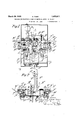
1g. 1 is a plain view of one constructive embodiment of the invention;
raw-
Fig. 2 represents a section taken on line 2-2 of Fig. 1;
Fig.3 is a section taken on line 3-3 of Fig. illustrates a detail of the structure shown in Fig. 1 along a section taken on line 4-4 of the latter;
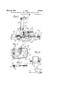
, Fig. 5 is a detail of the bobbin actuating mechanism asseen in a section taken on line 5-5 of Fig. 1;
I Fig. 6 is an end view, partially in section,
of the bobbin structure;
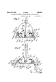
Fig. 7 shows the machine represented in Fi 1 and 3 adjusted to receive a circular ob ect such as an automobile tire;
l i 8 shows the same machine adjusted to handle straight bars.
Referring to the various figures of the drawings, there is shown an assembly comosed of the following elements: a C-shaped bbin support a having teeth formed on the periphery thereof and supported on an annular ring of anti-friction or like metal I); a frame supporting bobbin a and fitting into an opening in table d; means fordriving bobbin a com risin a chain e, a plurality of sprocket w eels f and f, wheel f being driven from .a s aft 9 actuated by a motor it through the intermediary of a clutch of any convenient design i; means for displacing bobbin a so as to center the latter rovide novel means by permanently attaching disc 1:. to shaft m and winding piano cord 1 in an one of grooves m m or m, formed in s aft m and a spring n attached to shaft m and adapted to exert pressure on a roll of wrapping material j; and means for guiding and displacing the object to be wrapped through the machine comprising a plurality of pulleys 12 and p pulley 12 being mounted to move along a vertical bar 9 and being rotated by a shaft driven from shafts 1 and g by means 0 appropriate gears, while ulleys p are pivotal y mounted on levers p y means of arms p coacting with fixed sectors said pulleys 1) being rotated in the same direction as pulley p by chains p (Fig. 1) driven from shafts g and g by appropriate gearsf fixed rollers 1' and r positioned on opposite sides of the bobbin and rotating in the same direction as the three pulleys p, p, 12. said rollers being driven from shafts g mounted in driven re ation to shaft g,supplemental rollers s a, supported on a movable pedestal s bolted in any one of a number of holes 8 formed in the table, said last named rollers being driven by belts a passing over any one of the pulleys such as p, the tension on belt a being adjustable by either taking in or letting out the latter, or by changing the position of the pulley over which it passes (the pulle s such as p may be mounted to slide axia' ly so as to avoid too great an obliquity of the belts) ,--additional rollers s plvotally mounted and counterweighted at a and adapted to be moved into position to guide an object being wrapped,rollers t slidably mounted in guides t and co-acting with rol ers 1' drivenfrom shaft 9 and springs t serving to apply the object being wrapped to rollers r.
The hereinabove described assembly functions in the following manner: assuming that the object is in the nature of an automobile tire, pulley p is moved along bar g and pulleys p are adjusted .by means of arms 1), the latter being fixed in position relatively to sectors by any convenient locking means (Fig. 7 discs at, n are then adjusted to receive a proper width of wrapping band by inserting piano "wire 1 in one of the grooves m, m or m; if it be desired to simultaneously wrap with cloth and paper band, 2 rolls are mounted in spaced relation in holes m formed in bobbin a; an object being positioned in the machine, handle is is rotated toraise or lower bobbin a until the latter'is spaced at e ual distances on all sides from the object, w ereby' wrapping roll 9' will remain at a bobbin (1 rollers .9 s, s are then adjusted to lie in contact. with the object; as soon as motor h is started rollers 1', 1, 8 s and pulle s p and p will rotate and displace the ob ect through bobbin a; at the same time, chain e, engaging with the teeth on the periphery of bobbin a, will rotate the latter and roll or rolls j mounted thereon; the object to be wrapped will, thereupon, re ceive a spiral of wrapping material.
If the object to be wrapped is rectilinear, the various rollers and pulleys are moved into the position shown in Figure 8. Rotation of motor h, will then displace the bar through the bobbin opening while roll moves thereabout.
- Rollers s serve principally to maintain a flexible material such as wire, or the like, in positionwhile being wrapped.
In prior machines complicated ear systems or belts were used for driving bbin a. When gear systems were used, the opening in bobbin (1 had to be limited in size. When belts were employed, the bobbin skidded during the period in which the belt straddled 66 tions of two of said pulleys relatively to one the gap in the periphery of the bobbin. By using a chain drive, neither of the foregoing disadvantages are encountered.
The use of centering system k, k, 70 70 permits roll j to move at a substantially constant distance from the object being wrapped and thus does away with inequalities in tension of the band of wrapping material.
As will be seen from Figs. 1, 2 and-.8, by properly positioning rollers s and s, and pulleys p and 19 a circular object'like an automobile tire may be wrapped in a vertical (Fig. 1) or in a horizontal position (Figs. 1 and 2). a
What I claim is 1; In a wrapping machine, a bobbin, and means for displacing an object to-be wrapped through said bobbin, said means comprisingthree pulleys positioned in a common plane, meansfor independently changing the posianother and to the third ulley, and means for driving one of said pu eys.
2. A structure as defined in claim 1 in combination with a roller mounted with its axis at right angles to the axis of one of said pulleys, and means for driving said roller.
3. A structure as defined in claim 1, in combination with a roller positioned so that its axis forms an angle with an axis of one of said pulleys, and means for driving. said roller.
4. A structure as defined in claim 1 in combination with'a roller havin a fixed axis, a second roller having an ad ustable axis, means for mounting the axis of said last named roller in an predetermined position of adjustment, an 1 means for driving said rollers.
- 5. In a wrapping machine, a support for a roll of wrapping material comprising a shaft having a plurality of grooves formed thereon, a first disc connected to said shaft, a second disc mountable in spaced relation to said first disc, and a wire inserted in one of said grooves and limiting the lateral 9 .movement of said second disc on said shaft.
6. In a wrapping machine, a bobbin having an opening in the peripher thereof, means for rotating said bobbin, a rame supporting said bobbin, said frame bein pivotally mounted, and means for angular y displacing said frame about its pivotal axis.
In testimony whereof I aflix my signature.
, I OSGAR THIRY.
Applications Claiming Priority (1)
| Application Number | Priority Date | Filing Date | Title |
|---|---|---|---|
| BE1851877X | 1929-12-03 |
Publications (1)
| Publication Number | Publication Date |
|---|---|
| US1851877A true US1851877A (en) | 1932-03-29 |
Family
ID=3895243
Family Applications (1)
| Application Number | Title | Priority Date | Filing Date |
|---|---|---|---|
| US497315A Expired - Lifetime US1851877A (en) | 1929-12-03 | 1930-11-21 | Machine for wrapping alpha band of material around an object |
Country Status (1)
| Country | Link |
|---|---|
| US (1) | US1851877A (en) |
-
1930
- 1930-11-21 US US497315A patent/US1851877A/en not_active Expired - Lifetime
Similar Documents
| Publication | Publication Date | Title |
|---|---|---|
| US2424021A (en) | Spooling | |
| US2346990A (en) | Method and means for forming window blind slat stock | |
| US2653773A (en) | Wire-spooling apparatus | |
| US1851877A (en) | Machine for wrapping alpha band of material around an object | |
| US1570821A (en) | Machine for the manufacture of bead cables or grommets | |
| US2461231A (en) | Winding machine | |
| US4106709A (en) | Method of and apparatus for serving helical coils with a protective band | |
| US2281328A (en) | Motion picture projector | |
| US2167087A (en) | Pipe cleaning apparatus | |
| US3988916A (en) | Apparatus for coiling striplike material | |
| US1265640A (en) | Tire-wrapping machine. | |
| SE432692B (en) | CIGAR RENDER WINDING DEVICE | |
| US1507258A (en) | Winding of cinematograph films and the like | |
| US1365066A (en) | shoopman | |
| US2487153A (en) | Apparatus for making belts | |
| JP6496283B2 (en) | Cable feeding device | |
| US700713A (en) | Machine for covering coils of wire. | |
| US1880770A (en) | Wiping apron for pipe wrapping machines | |
| US1237811A (en) | Adjusting mechanism for wrapping-machines. | |
| US1263924A (en) | Double-wrapper wrapping-machine. | |
| US3640025A (en) | Workpiece advancing means | |
| US192962A (en) | Improvement in cloth-measuring machines | |
| KR102401366B1 (en) | Machine for split to fabrics | |
| JPH04289251A (en) | Apparatus for transmitting power to fabric-feeding roll of circular knitting machine | |
| US1196044A (en) | stbvbns |