US1851876A - Locking device - Google Patents
Locking device Download PDFInfo
- Publication number
- US1851876A US1851876A US466224A US46622430A US1851876A US 1851876 A US1851876 A US 1851876A US 466224 A US466224 A US 466224A US 46622430 A US46622430 A US 46622430A US 1851876 A US1851876 A US 1851876A
- Authority
- US
- United States
- Prior art keywords
- drawers
- locking
- trays
- locking device
- cabinet
- Prior art date
- Legal status (The legal status is an assumption and is not a legal conclusion. Google has not performed a legal analysis and makes no representation as to the accuracy of the status listed.)
- Expired - Lifetime
Links
- 238000010276 construction Methods 0.000 description 2
- 230000004308 accommodation Effects 0.000 description 1
- 210000000038 chest Anatomy 0.000 description 1
- SPTYHKZRPFATHJ-HYZXJONISA-N dT6 Chemical compound O=C1NC(=O)C(C)=CN1[C@@H]1O[C@H](COP(O)(=O)O[C@@H]2[C@H](O[C@H](C2)N2C(NC(=O)C(C)=C2)=O)COP(O)(=O)O[C@@H]2[C@H](O[C@H](C2)N2C(NC(=O)C(C)=C2)=O)COP(O)(=O)O[C@@H]2[C@H](O[C@H](C2)N2C(NC(=O)C(C)=C2)=O)COP(O)(=O)O[C@@H]2[C@H](O[C@H](C2)N2C(NC(=O)C(C)=C2)=O)COP(O)(=O)O[C@@H]2[C@H](O[C@H](C2)N2C(NC(=O)C(C)=C2)=O)CO)[C@@H](O)C1 SPTYHKZRPFATHJ-HYZXJONISA-N 0.000 description 1
Images
Classifications
-
- E—FIXED CONSTRUCTIONS
- E05—LOCKS; KEYS; WINDOW OR DOOR FITTINGS; SAFES
- E05B—LOCKS; ACCESSORIES THEREFOR; HANDCUFFS
- E05B65/00—Locks or fastenings for special use
- E05B65/46—Locks or fastenings for special use for drawers
- E05B65/462—Locks or fastenings for special use for drawers for two or more drawers
Definitions
- This invention relates to new and useful improvements in locking devices for use upon cabinet drawers and trays.
- One of the principal objects of the invention consists of locking elements for engaging the drawers or trays from the side.
- Another object of the invention contemplates the provision and arrangement of lid engaging means for the locking elementto facilitate locking of the drawers or trays upon the occasion of the lid being shifted to occupy a closed position.
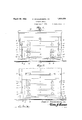
- Figure 1 is a front elevation of the present invention.
- Figure 2 is a view similar to Figure 1 with the lid or closure shifted to occupy an open v position.
- Figure 3 is a vertical sectional view taken on line 8-3 of Figure 1.
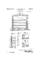
- Figure 4 is a fragmentary sectional view taken through the invention showing the i locking means released.
- Figure 5 is a det-ail sectional view showing the locking members in operative position.
- Figure 6 is a view similar to Figure 5 with the locking members released.
- Figure 7 is a perspective view of one of the locking elements.
- the reference character 10 indicates generally a form of cabinet having a multiplicity of drawers or trays 11, 12 and 13 and a closure lid 14.
- the locking elements are in the nature of relatively iiat elongated plates 17 positioned within slots 18 in the cabinet body i and through which said plates may be shifted for accommodationwithin slots 19 in the adjacent portions of the respective slides, trays or drawers.
- Pin members 19' carried by the cabinet body and projecting through the slots 18, are also passed through upwardly and outwardly inclined openings 20 in the plate members 17 to serve the combined purpose of limiting shifting motion of the plate members and to facilitate guiding of the locking elements to occupy either of their respective positions shown in Figures 5 and 6.
- the lid or closure 14 upon being swung to occupy a closed position will engage the uppermost protruding ends of the plate members or locking elements and shift the latter downwardly and inwardly, against the tension of the spring elements 21 whereby the innermost portions of the plate members or locking elements will be disposed Within the slots or pockets 19 in the ends of the respective slides, trays or drawers.
- said slots receiving said pins and being inclined downwardly toward the side edges of the drawers, the drawers being provided attheir side edges with recesses adapted to receive the edge portion of said bar, a spring located in the case below the set of drawers and bearing against the lower end of said bar to normally hold the upper end of the bar above the upper edge of the case and to hold the edge of the bar away from the recesses in the drawers and a lid for the case adapted when closed to move the bars in a downward Y direction7 whereby the pins and slots shift the bars into the recesses of the drawers.
Landscapes
- Closures For Containers (AREA)
Description
(lA SPANGENBERG. SR
March 29, 1932.
l L'OCKING DEVICE 2 Sheets-Sheet LOCKING DEVICE Filed July 7, 1950 2 Sheets-Sheet 2 INVENTOQ CHARLES 5PANGEM3E& Je.
TTTTTT EY Patented Mar. 29, 1932 UNITED STATES CHAR-LES SPANGENIBERG, SR.; OF PESHTIGO', TT'ISCVZONSIIN'` LOCKING DEVICE Application fried Juiy 7, 1930. semi No. 466,224.
This invention relates to new and useful improvements in locking devices for use upon cabinet drawers and trays.
One of the principal objects of the invention consists of locking elements for engaging the drawers or trays from the side.
Another object of the invention contemplates the provision and arrangement of lid engaging means for the locking elementto facilitate locking of the drawers or trays upon the occasion of the lid being shifted to occupy a closed position.
With the above and other objects in view, the invention further consists of the follow- "5 ing novel features and details of construction, to be hereinafter more fully described, illustrated in the accompanying drawings and pointed out in the appended claim.
ln the drawings Figure 1 is a front elevation of the present invention.
Figure 2 is a view similar to Figure 1 with the lid or closure shifted to occupy an open v position.
i3" Figure 3 is a vertical sectional view taken on line 8-3 of Figure 1.
Figure 4 is a fragmentary sectional view taken through the invention showing the i locking means released.
Figure 5 is a det-ail sectional view showing the locking members in operative position.
Figure 6 is a view similar to Figure 5 with the locking members released.
Figure 7 is a perspective view of one of the locking elements.
Referring to the drawings in detail wherein like characters of reference denote corresponding parts, the reference character 10 indicates generally a form of cabinet having a multiplicity of drawers or trays 11, 12 and 13 and a closure lid 14. Guide members or supports, such as indicated at 15, arranged in spaced parallelism upon the inner sides of y the cabinet, are designed for accommodation within raceways 16 in the end walls of the respective trays or drawers. The locking elements, alluded to in the foregoing, are in the nature of relatively iiat elongated plates 17 positioned within slots 18 in the cabinet body i and through which said plates may be shifted for accommodationwithin slots 19 in the adjacent portions of the respective slides, trays or drawers. Only two of these plates or locking elements are needed for the locking of all three drawers from both ends. Pin members 19', carried by the cabinet body and projecting through the slots 18, are also passed through upwardly and outwardly inclined openings 20 in the plate members 17 to serve the combined purpose of limiting shifting motion of the plate members and to facilitate guiding of the locking elements to occupy either of their respective positions shown in Figures 5 and 6. Spring members 21, carried within the base or bottom for the cabinet and flexing within compartments 22, especially provided for the purpose, are designed for contacting engagement with the lowermost ends of the plate members or locking elements to normally induce the latter to occupy the positions shown in Figure 2.
As suggested in Figures 1 and 3 of the drawings, the lid or closure 14 upon being swung to occupy a closed position will engage the uppermost protruding ends of the plate members or locking elements and shift the latter downwardly and inwardly, against the tension of the spring elements 21 whereby the innermost portions of the plate members or locking elements will be disposed Within the slots or pockets 19 in the ends of the respective slides, trays or drawers.
Although I have shown and described my invention upon a cabinet of this character, it is obviously understood that I do not limit the invention toV this particular instance of its application, inasmuch as a locking device of this character could be equally and effectually as well applied upon wardrobe trunks, chests of drawers and the like.
The invention is susceptible of various changes in its form, proportions and minor details of construction and the right is herein reserved to make such changes as properly fall within the scope of the appended claim.
Having described the invention, what is Y claimed is:
angle to the longitudinal dimension thereof, said slots receiving said pins and being inclined downwardly toward the side edges of the drawers, the drawers being provided attheir side edges with recesses adapted to receive the edge portion of said bar, a spring located in the case below the set of drawers and bearing against the lower end of said bar to normally hold the upper end of the bar above the upper edge of the case and to hold the edge of the bar away from the recesses in the drawers and a lid for the case adapted when closed to move the bars in a downward Y direction7 whereby the pins and slots shift the bars into the recesses of the drawers.
In testimony whereof I aHX my signature.
CHARLES SPANGENBERG, SR.
Priority Applications (1)
| Application Number | Priority Date | Filing Date | Title |
|---|---|---|---|
| US466224A US1851876A (en) | 1930-07-07 | 1930-07-07 | Locking device |
Applications Claiming Priority (1)
| Application Number | Priority Date | Filing Date | Title |
|---|---|---|---|
| US466224A US1851876A (en) | 1930-07-07 | 1930-07-07 | Locking device |
Publications (1)
| Publication Number | Publication Date |
|---|---|
| US1851876A true US1851876A (en) | 1932-03-29 |
Family
ID=23850967
Family Applications (1)
| Application Number | Title | Priority Date | Filing Date |
|---|---|---|---|
| US466224A Expired - Lifetime US1851876A (en) | 1930-07-07 | 1930-07-07 | Locking device |
Country Status (1)
| Country | Link |
|---|---|
| US (1) | US1851876A (en) |
Cited By (3)
| Publication number | Priority date | Publication date | Assignee | Title |
|---|---|---|---|---|
| DE1153655B (en) * | 1959-01-27 | 1963-08-29 | Hubert Lauer | Central lock for drawers on office furniture |
| US20060181182A1 (en) * | 2005-02-11 | 2006-08-17 | Super Test Corp. | Cabinet drawer drivingly connected locking mechanism |
| US20110121695A1 (en) * | 2005-06-24 | 2011-05-26 | Pdy Systems Lp | Storage unit |
-
1930
- 1930-07-07 US US466224A patent/US1851876A/en not_active Expired - Lifetime
Cited By (3)
| Publication number | Priority date | Publication date | Assignee | Title |
|---|---|---|---|---|
| DE1153655B (en) * | 1959-01-27 | 1963-08-29 | Hubert Lauer | Central lock for drawers on office furniture |
| US20060181182A1 (en) * | 2005-02-11 | 2006-08-17 | Super Test Corp. | Cabinet drawer drivingly connected locking mechanism |
| US20110121695A1 (en) * | 2005-06-24 | 2011-05-26 | Pdy Systems Lp | Storage unit |
Similar Documents
| Publication | Publication Date | Title |
|---|---|---|
| US1648277A (en) | Sectional bin | |
| US3277598A (en) | Frames for use in storing photographic slides | |
| US3030163A (en) | Nesting slide drawer receptacle | |
| US1851876A (en) | Locking device | |
| US1934532A (en) | Sign frame | |
| US1767823A (en) | Counter attachment | |
| US2119407A (en) | Means for filing micro-slides | |
| US792427A (en) | Office-étagere for filing and storing letters, &c. | |
| US244818A (en) | File-cabinet for court-papers | |
| US3149843A (en) | Gameboard with playing piece compartment | |
| US1136505A (en) | Packaging device. | |
| US1316015A (en) | Letter and document distributer | |
| US2026362A (en) | Budget box | |
| US675266A (en) | Folding brush. | |
| US1030121A (en) | Metallic receptacle. | |
| US1439929A (en) | Knockdown bottle case | |
| US456708A (en) | preston | |
| US1728946A (en) | Card-tray cabinet | |
| US362306A (en) | Label-cabinet | |
| US1685536A (en) | Drawer slide | |
| US1077826A (en) | Extension-table. | |
| US3149892A (en) | File cabinet marker | |
| US2968398A (en) | Desk drawer divider | |
| US221589A (en) | Improvement in egg and fruit carriers | |
| US978059A (en) | Portable shelf. |