US1851874A - Propeller for flying machines - Google Patents
Propeller for flying machines Download PDFInfo
- Publication number
- US1851874A US1851874A US447696A US44769630A US1851874A US 1851874 A US1851874 A US 1851874A US 447696 A US447696 A US 447696A US 44769630 A US44769630 A US 44769630A US 1851874 A US1851874 A US 1851874A
- Authority
- US
- United States
- Prior art keywords
- blades
- propeller
- hub
- spring
- bevel
- Prior art date
- Legal status (The legal status is an assumption and is not a legal conclusion. Google has not performed a legal analysis and makes no representation as to the accuracy of the status listed.)
- Expired - Lifetime
Links
- 230000006835 compression Effects 0.000 description 2
- 238000007906 compression Methods 0.000 description 2
- 230000008878 coupling Effects 0.000 description 2
- 238000010168 coupling process Methods 0.000 description 2
- 238000005859 coupling reaction Methods 0.000 description 2
- 101100096502 Danio rerio spring gene Proteins 0.000 description 1
- 101100096504 Mus musculus Spring1 gene Proteins 0.000 description 1
- 208000003251 Pruritus Diseases 0.000 description 1
- 101100426090 Rattus norvegicus Trim9 gene Proteins 0.000 description 1
- 101100096505 Xenopus laevis spring1 gene Proteins 0.000 description 1
- 238000010276 construction Methods 0.000 description 1
- 210000003746 feather Anatomy 0.000 description 1
- 230000037431 insertion Effects 0.000 description 1
- 238000003780 insertion Methods 0.000 description 1
- 229920000136 polysorbate Polymers 0.000 description 1
- 230000000717 retained effect Effects 0.000 description 1
- 230000000630 rising effect Effects 0.000 description 1
Images
Classifications
-
- B—PERFORMING OPERATIONS; TRANSPORTING
- B64—AIRCRAFT; AVIATION; COSMONAUTICS
- B64C—AEROPLANES; HELICOPTERS
- B64C11/00—Propellers, e.g. of ducted type; Features common to propellers and rotors for rotorcraft
- B64C11/30—Blade pitch-changing mechanisms
- B64C11/32—Blade pitch-changing mechanisms mechanical
- B64C11/34—Blade pitch-changing mechanisms mechanical automatic
- B64C11/343—Blade pitch-changing mechanisms mechanical automatic actuated by the centrifugal force or the aerodynamic drag acting on the blades
Definitions
- propellers for flying machines in which the position of the blades can ment of the rotating blades on the one hand and the action of a spring encompassing the axis. of the propeller shaft or hub on the U other hand.
- the present invention relates to a propeller of this type, and the progress of this improved propeller over the known ones resides therein that that compensation is effected ontheshortest way imaginable.
- the problem on which the present invention is based is to utilize the centrifugal force arising when the propeller is rotating for turning the blades around their own axes. It would seem to suggest itself to screw the blades upon pivots extending radially forth from'the hub and having a quick-pitch thread which. is frictionless in such a degree that it does not lock by its own action, so that when 7 a pressure or a pull is exerted in the direction of the thread axis the blades screw themselves upwardly or downwardly, as the case may be. But in View of the enormously great centrifugal force arising when the propeller is rotating that solution proves to be practically impossible.
- Figure 1 which is comletely like the upper part being omitted in ig. 2 from want of space
- Figure 3 is a section like Fig. 2, but certain parts being in another position
- Figure 4 is a transverse section through one of the blade bearings (blade socket and socket holding pivot), seen in the direction from the propeller shaft to the free blade end or tip
- Figure 5 is a view similar to the lefthand end of Fig. 1, showing a certain part in another position, all as fully described hereinafter.
- the sockets of the blades 1' and 2 are screwed upon pivots 12 projecting forth from the hub 3 of the propeller.
- the external thread of said pivots and the internal thread of the bores of the blade sockets are so designed that a helical groove (Fig. 1) having a circular or elliptic or rectangular transverse section is formed between said threads.
- This groove is filled with anti-friction balls 4 so that the blades run, as it were, on ball bearin s.
- a bevel-wheel 5 is supported on the hub 3 of the propeller, and is subjected to the pressure of a compression and torsion spring 7 encompassing the hub.
- the outer end of this spring bears upon, and is connected with a flange 13 of the hub, and the inner end bears upon, and is connected with, said bevel-wheel.
- This wheel meshes with two segmental bevel-wheels, or bevel-wheel segments 11 (Figs. 1 and 4) afiixed to the blades so that these latter are, in this way, positively connected with one another and are also subjected to the action of the spring 7 which continuously tends to counter-act the turning of the blades upon the pivots 12.
- the teeth of the bevel-wheel segments 11 risein the direction from one endof the series of teeth to the other end thereof in correspondence with the itch of the helical groove formed by and etween the internal and the external thread mentioned so that the engagement between the sectors and the bevel-wheel 5' is maintained when the blade sockets turn on the pivots radially outwards.
- the spring 7 is not only a compression spring, but also a torsion spring, it counteracts elastically also any force tending to subject it to torsional stress, and the centrifu al force arising in the blades when the propel er is rotating is, thus, transformed .into a partforce which tends to screw the blades outwardly until that force has been compensated by the torsional stress to which the spring has been subjected.
- the number of the blades may be as desired.
- the positive connection of the blades with the spring instead of being established by the toothed segments 11 and the bevel-wheel 5, may beestablished also by ropes or thrust rods or other equivalent members, and instead of using one only torsional spring as counteracting member for the two or more blades, a plurality of springs may be provided which, either, are attached directly to the individual blades or are coupled with one an other by the toothed members 5 and 11 conjointly.
- the balls 4 are held together preferabl'y by means of a tubular cage 14.
- a semicircular abutment and guide member 20 Opposite either the inner frontal edge of the cage (i. e. the edge opposite the hub of the propeller) or opposite the outer frontal edge of the cage (i. e. the edge opposite the blade proper) is a semicircular abutment and guide member 20, which is inclined in conformity with the pitch of the helical groove so that the cage is always in contact with that member and is retained by it in its proper position irrespective of the turning of the appertaining blade on its pivot.
- said member 20 is located opposite the outer end of said cage.
- each blade on its pivot that is to say, the.degree or extent of its angular motion
- a lug 15 (Figs. 2 and 3) projecting radially forth from the hub of the propeller and co-operating with lugs 16 and 17 projecting forth radially inwards from the hub ends of the blades, one or the other of these latter lugs contacting with the lug 15 of the hub in the respective end-position.
- lugs 15, 16. and 17 form, thus, abutment members, and besides these three abutment members there is a.
- abutment member 19 that is located, and shiftable, upon the member 15 and can be connectedwith it in its adjusted position.
- the abutment member 19 is in contact with the lefthand side of the abutment mem ber 18, and in Fig. 3 it engages the space between the'abutment members 17 and 18.
- a sleeve 19 (Fig. 5) which is coupled with the propeller shaft by feather and groove and can, thus, be shifted on it, but rotates with it.
- the sleeve 19 may be actuated by any suitable means.
- Fig. 5 the sleeve with its abutment members 19 is shown withdrawn from the abutment members 18, so that the members 19 co-operatesolely with the members 16 and 17.
- the abutment member 18 is of lesser height than the members 16 and 17.
- the intermediate abutment member 18 does not come in contact with it, but when it is in its operative position, it depends upon the position of the blade whether the amount of the turning movement of the blade is limited by the abutment members 18 and 16 or 18 and 17.”
- a propeller for flying machines having blades, the pitch of which can be adjusted or readjusted automatically by the cent-rifugal force arising While the propeller ro-' ally outwards from the hub, and abutment members projecting radially inwards from the hub ends of the said blades, the arrangement of said abutment members relatively to one another being such that the amount of turning of the blades around their axes is limited; a torsion spr ing arranged co-axially with the propeller axis, and coupling means between this spring and the blades and adapted to transmit the torsional force of said spring to the blades in such a manner that this force counteracts the turning of the blades around their axes.
- a propeller for flying machines having blades, the pitch of which can be adjusted or readjusted automatically by the centrifugal force arising while the propeller rotates, comprising, in combination with said bladcs and with internally threaded bores in the hub ends of the blades, pivots projecting forth from the hub of the propeller end eugaging said bores and being externally threaded in such a manner that this thread together with that of the blade bore forms a helical groove; anti-friction balls in this groove; a torsion spring arranged (o-axially with the propeller shaft; coupling members connecting the blades with said spring in such a manner that said force counteracts the turning of the blades around their axes; abutment members projecting radially outwards from the hub; abutment members projecting radially inwards from the hub ends of the blades, the arrangement of said abutment members relatively to one another being such that the amount of turning of the blades around their axes is limited; a
- a propeller for flying machines having blades, the pitch of which can be adjusted or readjusted automatically by the centrifugal force arising while the propeller rotates, comprising, in combination with said blades, pivots extendingradially from the hub of the propeller and having the blades attached to them and having each a helical groove in its circumferential surface, a corresponding groove being provided in the opposite surface of the appertaining blade bore enclosing the appertaining pivot; balls in the hollow screw-thread formed by the oppositely located grooves, a torsion-spring surrounding the hub and being at one end connected therewith, a bevel-wheel supported upon the hub and being connected with the other end of-said spring; and segment-forming sets of bevel-teeth provided at the hub-ends of the blades and meshing with said bevel-wheel so as to transmit the rotational force produced by the action of the centrifugal force upon the blades to the said spring, the strength of this latter being such that it is just able to counterbalance said forces,
- propeller for flying machines having blades, the pitch of which can be adjusted or readjusted automatically by the centrifugal force arising while the propeller'rotates, comprising, in combination with said, blades, pivots extending radially from the hub of the propeller and having the blades at tached to them and having each a helical groove in.
- a propeller for flying machines having blades, the pitch of which can be adjusted or readjusted automatically'by the centrifugal force arising while the propeller rotates, comprising, in combination with said blades, pivots extending radially from the hub of the propeller and having the blades attached to them and having each a helical groove in its circumferential surface, a corresponding groove being provided in the opposite surface of the appertaining blade bore enclosing the appertaining pivot, balls in the hollow screw-thread formed by the oppositely located grooves, cages, each of which is located between one of said pivots and the corresponding blade portion and holding the appertaining balls in their proper position with respect to oneanother, and uide members each having a guide surface inclined in correspondence with thepitch of said screw thread and being so arranged relatively to one of the edges of the appertaining cage as to remain in contact therewith at any angular position of the appertaining blade; a torsionspring surrounding the hub and being at one end connected therewith; a bevel-wheel supported upon the
- a propeller for flying machines having blades, the pitch of which can be adjusted or readjusted automatically by the centrifugal force arising while the propeller rotates, comprising, in combination with said blades, pivots extending radially from the hub of the propeller and having the blades attached to them and having each a helical groove in its circumferential surface, a corresponding groove being provided in the opposite surface of the appertaining blade bore enclosing the appertaining pivot, balls in the hollow screw-thread formed by the oppositely located grooves, cages, each of whichis located bers having a guide surface inclined in corre-' spondence with the pitch of the screw-thread pertaining to the appertaining blade and its pivot and being so arranged relatively to 10 the edges of the appertaining cage as to remain in contact therewith at any angular position of the blade; a torsion-spring surrounding the hub and being at one end connected therewith; a bevel-wheel supported upon the hub and being connected with the other end of said spring; and segment-forming sets of
- a propeller for fiyingmachines having blades, the pitch of which can be adjusted or readjusted automatically by the centrifugal force arising while the propeller rotates, comprising, in combination with said blades, pivots extending radially from the hub of the propeller and having the blades attached to them and having each a helical groove in its circumferential surface, a corresponding groove being provided in the opposite surface of the appertaining blade bore'enclosing the appertaining pivot; balls in the hollow screwthread formed by .the oppositely located grooves, a torsion-spring surrounding the hub and being at one end connected therewith; a bevel-wheel supported upon the hub and being connected with the other end of said spring; and segment-forming sets of beve1- teeth provided at the hub-ends of the blades and meshing with said bevel-wheel so as to transmit the rotational force produced by the action of the centrifugal force upon vthe blades to thesaid spring, the strength of this latter being 'sluch that it is just able
Landscapes
- Engineering & Computer Science (AREA)
- Physics & Mathematics (AREA)
- Fluid Mechanics (AREA)
- Mechanical Engineering (AREA)
- Aviation & Aerospace Engineering (AREA)
- Structures Of Non-Positive Displacement Pumps (AREA)
Description
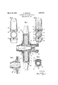
March 29, 1932. E. SEPPELER PROPELLER FOR FLYING MACHINES Filed April 26. 1950 FIG. 3
a I a Patented Mar. 29, 1932 EDUARD SEIPPELER, OF BERLIN-NEUKOLLN, GER-MANY PROPELLER FOR FLYING MACHINES Application filed April 26, 1930, Serial No. 447,696, and in Germany January 16, 1929.
There are known propellers for flying machines in which the position of the blades can ment of the rotating blades on the one hand and the action of a spring encompassing the axis. of the propeller shaft or hub on the U other hand. Also the present invention relates to a propeller of this type, and the progress of this improved propeller over the known ones resides therein that that compensation is effected ontheshortest way imaginable.
The problem on which the present invention is based is to utilize the centrifugal force arising when the propeller is rotating for turning the blades around their own axes. It would seem to suggest itself to screw the blades upon pivots extending radially forth from'the hub and having a quick-pitch thread which. is frictionless in such a degree that it does not lock by its own action, so that when 7 a pressure or a pull is exerted in the direction of the thread axis the blades screw themselves upwardly or downwardly, as the case may be. But in View of the enormously great centrifugal force arising when the propeller is rotating that solution proves to be practically impossible. In the present actual, and practically at once possible, solution of the problem stated the blades are screwed upon the hub pivots with the insertion of anti-friction balls forming, as it were, a helical ball bearing within the blade. This construction renders it possible to reduce the friction in the threads very considerably and thereby to transform the centrifugal force into a turning motion of the win The invention is illustrated dla rammatically and by wayof example on t e accompanying drawings on which Figure 1 1s an F axial section through a propeller designed according to this invention, the section being taken in the plane II of F 2, F1gure'2 is a transverse section in the p ane IIII of Fig. 1, the. lower part of Fig. 1 which is comletely like the upper part being omitted in ig. 2 from want of space; Figure 3 is a section like Fig. 2, but certain parts being in another position; Figure 4: is a transverse section through one of the blade bearings (blade socket and socket holding pivot), seen in the direction from the propeller shaft to the free blade end or tip; and Figure 5 is a view similar to the lefthand end of Fig. 1, showing a certain part in another position, all as fully described hereinafter.
The sockets of the blades 1' and 2 are screwed upon pivots 12 projecting forth from the hub 3 of the propeller. The external thread of said pivots and the internal thread of the bores of the blade sockets are so designed that a helical groove (Fig. 1) having a circular or elliptic or rectangular transverse section is formed between said threads. This groove is filled with anti-friction balls 4 so that the blades run, as it were, on ball bearin s.
%n front of the blade sockets a bevel-wheel 5 is supported on the hub 3 of the propeller, and is subjected to the pressure of a compression and torsion spring 7 encompassing the hub. The outer end of this spring bears upon, and is connected with a flange 13 of the hub, and the inner end bears upon, and is connected with, said bevel-wheel. This wheel meshes with two segmental bevel-wheels, or bevel-wheel segments 11 (Figs. 1 and 4) afiixed to the blades so that these latter are, in this way, positively connected with one another and are also subjected to the action of the spring 7 which continuously tends to counter-act the turning of the blades upon the pivots 12.
The teeth of the bevel-wheel segments 11 risein the direction from one endof the series of teeth to the other end thereof in correspondence with the itch of the helical groove formed by and etween the internal and the external thread mentioned so that the engagement between the sectors and the bevel-wheel 5' is maintained when the blade sockets turn on the pivots radially outwards.
As the spring 7 is not only a compression spring, but also a torsion spring, it counteracts elastically also any force tending to subject it to torsional stress, and the centrifu al force arising in the blades when the propel er is rotating is, thus, transformed .into a partforce which tends to screw the blades outwardly until that force has been compensated by the torsional stress to which the spring has been subjected.
The number of the blades may be as desired.
The positive connection of the blades with the spring, instead of being established by the toothed segments 11 and the bevel-wheel 5, may beestablished also by ropes or thrust rods or other equivalent members, and instead of using one only torsional spring as counteracting member for the two or more blades, a plurality of springs may be provided which, either, are attached directly to the individual blades or are coupled with one an other by the toothed members 5 and 11 conjointly.
The balls 4 are held together preferabl'y by means of a tubular cage 14. Opposite either the inner frontal edge of the cage (i. e. the edge opposite the hub of the propeller) or opposite the outer frontal edge of the cage (i. e. the edge opposite the blade proper) is a semicircular abutment and guide member 20, which is inclined in conformity with the pitch of the helical groove so that the cage is always in contact with that member and is retained by it in its proper position irrespective of the turning of the appertaining blade on its pivot. In the constructional form shown in Fig. 1 said member 20 is located opposite the outer end of said cage.
The turning of each blade on its pivot, that is to say, the.degree or extent of its angular motion, is limited by means of a lug 15 (Figs. 2 and 3) projecting radially forth from the hub of the propeller and co-operating with lugs 16 and 17 projecting forth radially inwards from the hub ends of the blades, one or the other of these latter lugs contacting with the lug 15 of the hub in the respective end-position. In Fig. 3 this is the case as regards the lug 17. The lugs 15, 16. and 17 form, thus, abutment members, and besides these three abutment members there is a. fourth, 18, which is located between the members 16 and 17, and co-operates with a fifth abutment member 19 that is located, and shiftable, upon the member 15 and can be connectedwith it in its adjusted position. In Fig. 2 the abutment member 19 is in contact with the lefthand side of the abutment mem ber 18, and in Fig. 3 it engages the space between the'abutment members 17 and 18. As there are at least two ofeach of the abutment members 15, 16, 17 and 18, there are also a corresponding number of the abutment members 19, and these members form parts of a sleeve 19 (Fig. 5) which is coupled with the propeller shaft by feather and groove and can, thus, be shifted on it, but rotates with it. The sleeve 19 may be actuated by any suitable means. In Fig. 5 the sleeve with its abutment members 19 is shown withdrawn from the abutment members 18, so that the members 19 co-operatesolely with the members 16 and 17. The abutment member 18 is of lesser height than the members 16 and 17. When the additional abutment member 19 is withdrawn, the intermediate abutment member 18 does not come in contact with it, but when it is in its operative position, it depends upon the position of the blade whether the amount of the turning movement of the blade is limited by the abutment members 18 and 16 or 18 and 17."
In the first of these cases the blades'drive rearwardly with negative pitch, and in the other case they drive forwardly with positive pitch.
I claim:
1. A propeller for flying machines, having blades, the pitch of which can be adjusted or readjusted automatically by the cent-rifugal force arising While the propeller ro-' ally outwards from the hub, and abutment members projecting radially inwards from the hub ends of the said blades, the arrangement of said abutment members relatively to one another being such that the amount of turning of the blades around their axes is limited; a torsion spr ing arranged co-axially with the propeller axis, and coupling means between this spring and the blades and adapted to transmit the torsional force of said spring to the blades in such a manner that this force counteracts the turning of the blades around their axes.
2. A propeller for flying machines, having blades, the pitch of which can be adjusted or readjusted automatically by the centrifugal force arising while the propeller rotates, comprising, in combination with said bladcs and with internally threaded bores in the hub ends of the blades, pivots projecting forth from the hub of the propeller end eugaging said bores and being externally threaded in such a manner that this thread together with that of the blade bore forms a helical groove; anti-friction balls in this groove; a torsion spring arranged (o-axially with the propeller shaft; coupling members connecting the blades with said spring in such a manner that said force counteracts the turning of the blades around their axes; abutment members projecting radially outwards from the hub; abutment members projecting radially inwards from the hub ends of the blades, the arrangement of said abutment members relatively to one another being such that the amount of turning of the blades around their axes is limited; abutment memtween those of the blades, and being lower than them and so arranged with respect to the adjustable abutment members as to be adapted to cooperate with them, substantially as set forth.
3. A propeller for flying machines, having blades, the pitch of which can be adjusted or readjusted automatically by the centrifugal force arising while the propeller rotates, comprising, in combination with said blades, pivots extendingradially from the hub of the propeller and having the blades attached to them and having each a helical groove in its circumferential surface, a corresponding groove being provided in the opposite surface of the appertaining blade bore enclosing the appertaining pivot; balls in the hollow screw-thread formed by the oppositely located grooves, a torsion-spring surrounding the hub and being at one end connected therewith, a bevel-wheel supported upon the hub and being connected with the other end of-said spring; and segment-forming sets of bevel-teeth provided at the hub-ends of the blades and meshing with said bevel-wheel so as to transmit the rotational force produced by the action of the centrifugal force upon the blades to the said spring, the strength of this latter being such that it is just able to counterbalance said forces, the combination and arrangement of the parts being, for the rest, such that the driving power is transmitted from the propeller shaft to the said pivots with their blades directly, without any co-action of the said spring.
4. propeller for flying machines, having blades, the pitch of which can be adjusted or readjusted automatically by the centrifugal force arising while the propeller'rotates, comprising, in combination with said, blades, pivots extending radially from the hub of the propeller and having the blades at tached to them and having each a helical groove in. its circumferential surface, a corresponding groove being provided in the opposite surface of the appertaining blade bore enclosing the appertaining pivot, balls in the hollow screw-thread formed by the oppositely located grooves; cages, each of which is located between one of said pivots and the corresponding blade portion and holding the appertaining balls in their proper positionwith respect to one another; a torsion spring surrounding the hub and being at one end connected therewith; a bevel-wheel supported upon the hub and beingconnected with the other end of said spring; and segment-forming sets of bevel-teeth provided at the hub-ends of the blades and meshing with said bevel-wheel so as to transmit the rotational force produced by the action of the centrifugal force upon the blades to the said spring, the strength of this latter being suchthat it is just able to counterbalance said forces, the combination and arrangement of the parts being, for the rest, such that the driving power is transmitted from the propeller shaft to the said pivots with their blades directly, without any co-act-ion of the said spring.
5. A propeller for flying machines, having blades, the pitch of which can be adjusted or readjusted automatically'by the centrifugal force arising while the propeller rotates, comprising, in combination with said blades, pivots extending radially from the hub of the propeller and having the blades attached to them and having each a helical groove in its circumferential surface, a corresponding groove being provided in the opposite surface of the appertaining blade bore enclosing the appertaining pivot, balls in the hollow screw-thread formed by the oppositely located grooves, cages, each of which is located between one of said pivots and the corresponding blade portion and holding the appertaining balls in their proper position with respect to oneanother, and uide members each having a guide surface inclined in correspondence with thepitch of said screw thread and being so arranged relatively to one of the edges of the appertaining cage as to remain in contact therewith at any angular position of the appertaining blade; a torsionspring surrounding the hub and being at one end connected therewith; a bevel-wheel supported upon the hub and being connected with the other end of said spring; and segment-forming sets of bevel-teeth provided at the hub-ends of the blades and meshing with said bevel-wheel so as to transmit the rotational force produced by the action of the centrifugal force upon the blades to the said'spring, the strength of this latter being such that it is just able to counterbalance said forces, the combination and arrangement of thepartsbeing forthrest,such that the driving power is transmitted from the propeller shaft to the said pivots with their blades directly, without any co-action of the said SPIlIl 6. A propeller for flying machines, having blades, the pitch of which can be adjusted or readjusted automatically by the centrifugal force arising while the propeller rotates, comprising, in combination with said blades, pivots extending radially from the hub of the propeller and having the blades attached to them and having each a helical groove in its circumferential surface, a corresponding groove being provided in the opposite surface of the appertaining blade bore enclosing the appertaining pivot, balls in the hollow screw-thread formed by the oppositely located grooves, cages, each of whichis located bers having a guide surface inclined in corre-' spondence with the pitch of the screw-thread pertaining to the appertaining blade and its pivot and being so arranged relatively to 10 the edges of the appertaining cage as to remain in contact therewith at any angular position of the blade; a torsion-spring surrounding the hub and being at one end connected therewith; a bevel-wheel supported upon the hub and being connected with the other end of said spring; and segment-forming sets of bevel-teeth provided at the hubends of the blades and meshing with said bevel-wheel so as to transmit the rotational forceproduced by the action of the centrifugal force upon the blades to the said spring, the strength of this latter being such that it is just able to counterbalance said forces, the combination and arrangement of the parts being, for the rest, such that the driving power is transmitted from the propeller shaft to the said pivots with their blades directly, without any co-action of the said spring.
7. A propeller for fiyingmachines, having blades, the pitch of which can be adjusted or readjusted automatically by the centrifugal force arising while the propeller rotates, comprising, in combination with said blades, pivots extending radially from the hub of the propeller and having the blades attached to them and having each a helical groove in its circumferential surface, a corresponding groove being provided in the opposite surface of the appertaining blade bore'enclosing the appertaining pivot; balls in the hollow screwthread formed by .the oppositely located grooves, a torsion-spring surrounding the hub and being at one end connected therewith; a bevel-wheel supported upon the hub and being connected with the other end of said spring; and segment-forming sets of beve1- teeth provided at the hub-ends of the blades and meshing with said bevel-wheel so as to transmit the rotational force produced by the action of the centrifugal force upon vthe blades to thesaid spring, the strength of this latter being 'sluch that it is just able to counterbalance said'forces, the combination and arrangement of the parts being, for the rest, such that the driving power is transmitted from the propeller shaft to the said pivots with their blades directly, without-any coaction of the said spring and the teeth of said bevel-wheel segments rising in the direction from one end of the series of teeth to the other-end thereof in correspondence with the pitch of the helical groove formed by and between i the internal and the external tween the sectors and the bevel-wheel 5 is maintained when the blade sockets turn on the pivots radially outwards.
In testimony whereof I afiix my signature.
EDUARD SEPPELER.
Applications Claiming Priority (1)
| Application Number | Priority Date | Filing Date | Title |
|---|---|---|---|
| DE1851874X | 1929-01-16 |
Publications (1)
| Publication Number | Publication Date |
|---|---|
| US1851874A true US1851874A (en) | 1932-03-29 |
Family
ID=7746055
Family Applications (1)
| Application Number | Title | Priority Date | Filing Date |
|---|---|---|---|
| US447696A Expired - Lifetime US1851874A (en) | 1929-01-16 | 1930-04-26 | Propeller for flying machines |
Country Status (1)
| Country | Link |
|---|---|
| US (1) | US1851874A (en) |
Cited By (15)
| Publication number | Priority date | Publication date | Assignee | Title |
|---|---|---|---|---|
| US2425938A (en) * | 1943-09-15 | 1947-08-19 | Walter S Hoover | Circulating ball race propeller blade bearing |
| US2433990A (en) * | 1943-08-13 | 1948-01-06 | Marquette Metal Products Co | Controllable pitch propeller mechanism |
| US2444539A (en) * | 1943-05-11 | 1948-07-06 | Roy E Sharpes | Propeller mounting |
| US2455378A (en) * | 1943-11-27 | 1948-12-07 | Howard M Mccoy | Mechanism and controls for controllable aircraft propellers; complete propeller with automatic controls |
| US2487239A (en) * | 1943-02-19 | 1949-11-08 | Marquette Metal Products Co | Propeller for aircraft |
| US2498110A (en) * | 1945-03-10 | 1950-02-21 | Canadian Car And Foundry Compa | Two-position variable pitch propeller |
| US2504737A (en) * | 1944-09-07 | 1950-04-18 | Roy E Sharpes | Self-operating pitch changing propeller and control therefor |
| US2515037A (en) * | 1945-11-19 | 1950-07-11 | Marquette Metal Products Co | Controllable pitch propeller |
| US2609057A (en) * | 1945-02-11 | 1952-09-02 | Dehavilland Aircraft | Variable-pitch airscrew |
| US3308889A (en) * | 1965-07-06 | 1967-03-14 | Finn Bergishagen | Variable pitch propeller with automatic adjustment |
| US3403735A (en) * | 1967-03-10 | 1968-10-01 | Henrik G. Langhjelm | Adjustable variable pitch propeller |
| EP0143061A1 (en) * | 1983-11-23 | 1985-05-29 | Pierre Joulia | Propeller pitch automatic regulation device |
| US4842484A (en) * | 1983-08-29 | 1989-06-27 | General Electric Company | Blade gearing and pitch changing mechanisms for coaxial counterrotating propellers |
| US4948339A (en) * | 1989-01-23 | 1990-08-14 | General Electric Company | Propeller blade counterweight |
| US20090004008A1 (en) * | 2007-06-28 | 2009-01-01 | Rolls-Royce Plc | Blade mounting |
-
1930
- 1930-04-26 US US447696A patent/US1851874A/en not_active Expired - Lifetime
Cited By (16)
| Publication number | Priority date | Publication date | Assignee | Title |
|---|---|---|---|---|
| US2487239A (en) * | 1943-02-19 | 1949-11-08 | Marquette Metal Products Co | Propeller for aircraft |
| US2444539A (en) * | 1943-05-11 | 1948-07-06 | Roy E Sharpes | Propeller mounting |
| US2433990A (en) * | 1943-08-13 | 1948-01-06 | Marquette Metal Products Co | Controllable pitch propeller mechanism |
| US2425938A (en) * | 1943-09-15 | 1947-08-19 | Walter S Hoover | Circulating ball race propeller blade bearing |
| US2455378A (en) * | 1943-11-27 | 1948-12-07 | Howard M Mccoy | Mechanism and controls for controllable aircraft propellers; complete propeller with automatic controls |
| US2504737A (en) * | 1944-09-07 | 1950-04-18 | Roy E Sharpes | Self-operating pitch changing propeller and control therefor |
| US2609057A (en) * | 1945-02-11 | 1952-09-02 | Dehavilland Aircraft | Variable-pitch airscrew |
| US2498110A (en) * | 1945-03-10 | 1950-02-21 | Canadian Car And Foundry Compa | Two-position variable pitch propeller |
| US2515037A (en) * | 1945-11-19 | 1950-07-11 | Marquette Metal Products Co | Controllable pitch propeller |
| US3308889A (en) * | 1965-07-06 | 1967-03-14 | Finn Bergishagen | Variable pitch propeller with automatic adjustment |
| US3403735A (en) * | 1967-03-10 | 1968-10-01 | Henrik G. Langhjelm | Adjustable variable pitch propeller |
| US4842484A (en) * | 1983-08-29 | 1989-06-27 | General Electric Company | Blade gearing and pitch changing mechanisms for coaxial counterrotating propellers |
| EP0143061A1 (en) * | 1983-11-23 | 1985-05-29 | Pierre Joulia | Propeller pitch automatic regulation device |
| WO1985002383A1 (en) * | 1983-11-23 | 1985-06-06 | Pierre Joulia | Device for automatically adjusting the propeller pitch |
| US4948339A (en) * | 1989-01-23 | 1990-08-14 | General Electric Company | Propeller blade counterweight |
| US20090004008A1 (en) * | 2007-06-28 | 2009-01-01 | Rolls-Royce Plc | Blade mounting |
Similar Documents
| Publication | Publication Date | Title |
|---|---|---|
| US1851874A (en) | Propeller for flying machines | |
| US2235605A (en) | Screw propeller | |
| US2256918A (en) | Aircraft | |
| DE2648343C3 (en) | Flapping and swivel-less rotor for rotary wing aircraft | |
| US2154532A (en) | Propeller drive for oppositely rotating coaxial propellers | |
| US3545880A (en) | Rotor for rotary-wing aircraft | |
| CN110683049A (en) | A propeller hub device for a small tilt-rotor aircraft | |
| US1927966A (en) | Lifting air screw for air vehicles | |
| US2631680A (en) | Articulated blade | |
| GB124935A (en) | Improvements in Self Setting Sails or Blades of Windmills or of Tractor Screws or of Pusher Screws of Aeroplanes or Dirigibles. | |
| DE727968C (en) | Storage for during operation around their longitudinal axis rotatable blades of Verstelluftscrews | |
| US1982170A (en) | Variable pitch propeller | |
| KR102831500B1 (en) | aircraft | |
| US2640552A (en) | Propeller pitch change mechanism | |
| US2152419A (en) | Variable pitch propeller | |
| US2660252A (en) | Variable pitch screw propeller articulated blade mounting | |
| US1980272A (en) | Propeller | |
| US2391778A (en) | Variable pitch propeller | |
| US1871124A (en) | Variable pitch propeller | |
| US1903628A (en) | Airplane propeller | |
| US1920674A (en) | Variable pitch propeller | |
| CN214138983U (en) | Wing driving mechanism of unmanned aerial vehicle | |
| US2037251A (en) | Propeller | |
| US1952800A (en) | Automatic propeller | |
| US2645294A (en) | Variable pitch propeller |