US1851848A - Rolling mill roll - Google Patents
Rolling mill roll Download PDFInfo
- Publication number
- US1851848A US1851848A US374184A US37418429A US1851848A US 1851848 A US1851848 A US 1851848A US 374184 A US374184 A US 374184A US 37418429 A US37418429 A US 37418429A US 1851848 A US1851848 A US 1851848A
- Authority
- US
- United States
- Prior art keywords
- rolls
- roll
- recesses
- rolling mill
- mill roll
- Prior art date
- Legal status (The legal status is an assumption and is not a legal conclusion. Google has not performed a legal analysis and makes no representation as to the accuracy of the status listed.)
- Expired - Lifetime
Links
- 238000005096 rolling process Methods 0.000 title description 9
- 230000015572 biosynthetic process Effects 0.000 description 5
- 238000010276 construction Methods 0.000 description 2
- 238000010438 heat treatment Methods 0.000 description 2
- 241000276498 Pollachius virens Species 0.000 description 1
- 229910000746 Structural steel Inorganic materials 0.000 description 1
- 239000002184 metal Substances 0.000 description 1
- 229910052751 metal Inorganic materials 0.000 description 1
Images
Classifications
-
- B—PERFORMING OPERATIONS; TRANSPORTING
- B21—MECHANICAL METAL-WORKING WITHOUT ESSENTIALLY REMOVING MATERIAL; PUNCHING METAL
- B21B—ROLLING OF METAL
- B21B1/00—Metal-rolling methods or mills for making semi-finished products of solid or profiled cross-section; Sequence of operations in milling trains; Layout of rolling-mill plant, e.g. grouping of stands; Succession of passes or of sectional pass alternations
- B21B1/08—Metal-rolling methods or mills for making semi-finished products of solid or profiled cross-section; Sequence of operations in milling trains; Layout of rolling-mill plant, e.g. grouping of stands; Succession of passes or of sectional pass alternations for rolling structural sections, i.e. work of special cross-section, e.g. angle steel
- B21B1/082—Piling sections having lateral edges specially adapted for interlocking with each other in order to build a wall
Definitions
- Sheet-piling sections or similar shapes provided with long flanges are rolled by means of rolls which, depending upon the sections to be manufactured, are provided with very deep cut grooves and, if necessary, with collars of very heavy dimensions.
- these widely diflering diameters of a roll are very often liable to cause a fracture of the roll. These fractures in their turn cause heavy outlays for reconditioning as well as stoppage of'the mill which brings in its train cessation of reduction.
- this new roll construction will be applied in connection with the most severely worn out two or three high mills.
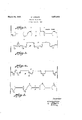
- Fig. 1 illustrates the known formation of rolls for I beams.
- Fig. 2 illustrates the formation of rolls for I beams according to the invention.
- Fig. 3 illustrates the formation of rolls for rolling sheet piling according to the invention.
- Fig.4 illustrates the formation of rolls for rolling channel iron according to the, inven tion.
- Fig. 2 illustrates rolls C and D for rolling I-beams which are provided with recesses for the purpose'stated.
- Roll C is provided with recesses 5, 6 and 7 while roll D is provided with recesses 8 and 9.
- Said recesses 5, 6, 7, 8 and 9 are specially shaped and well rounded, also being cut to a depth greater than the recessesfor any of the passes.
- Roll F is provided with recesses 10, 11, 12 and 13 which are deeper than any or the recesses for the passes, specially shaped and well rounded.
- Rolls G and H shown in Fig. 4, are especially adapted for rolling channel sections and roll H is provided wlth recesses 14, 15, 16, 17 and 18' according to the invention.
- the known roll is unequally heated in various sections during rolling and this unequal heating is increased in the case of various passes depending on the length of the bar bethe rolls adjacent the recessed square comers thereof.
- the manner of providing the recesses according to the invention promotes the equalization of heat in and elasticity of the rolls.
- the recesses being well rounded do not provide starting points for fraeturesand being of the depth specified diminish the tendency to unequal heating of the rolls.
- a roll of the character described having deep grooves for the passes of a rollin mill and provided at points of heat accumul between the passes in the roll with well rounded recesses exceeding both the depth of said dee grooves and the depth normally provided or laterally closing said passes.
Landscapes
- Engineering & Computer Science (AREA)
- Mechanical Engineering (AREA)
- Reduction Rolling/Reduction Stand/Operation Of Reduction Machine (AREA)
Description
March 29, 1932. w. KCHLER 1,851,848
ROLLING MILL ROLL Filed June 27, 1929 0 wit 2 3 TIA/0W FORM /n venzor:
W/Y/Ie/ Kb'b/er Q Afforney Patentedhlar. 29, 1932 UNITED STATES PATENT orrlca WILHELI K6HLER, O1! DOBTKUND, GERMANY, ASSIGNOR TO THE FIRM VEREINIG'I'E STAHLWERKE AKTENQEBELLSCEAI'I, OF DUSSH'DORF, GmANY Ronnie m1; non.
Application filed June 27, 1929, ScrialNc.
Sheet-piling sections or similar shapes provided with long flanges are rolled by means of rolls which, depending upon the sections to be manufactured, are provided with very deep cut grooves and, if necessary, with collars of very heavy dimensions. On account of the thermic tensions as well as the stresses to which-the rolls are subjected in service, these widely diflering diameters of a roll are very often liable to cause a fracture of the roll. These fractures in their turn cause heavy outlays for reconditioning as well as stoppage of'the mill which brings in its train cessation of reduction.
It is the o ject of the present invention to provide a rolling mill roll of such a sha e as to do away with fractures of rolls an the accompanying disadvantages to a large extent.
According to the invention this is being obtained by providing the collars adjoining the grooves in axial direction of the roll on their surfaces opposite the said grooves with channel'like recesses of a depth at least as great as that of the deepest grooves. By this arrangement the thermic tensions and stresses will be balanced in a much more advantageous way than is the case with rolls of ordinary construction, so that the development of cracks at the corners of the grooves as well as the occurrence of fractures will be reduced to a large extent by the new roll design:
Preferably this new roll construction will be applied in connection with the most severely worn out two or three high mills.
Reference is niade hereby to the accompanying drawings, wherein:
Fig. 1 illustrates the known formation of rolls for I beams.
Fig. 2 illustrates the formation of rolls for I beams according to the invention.
Fig. 3 illustrates the formation of rolls for rolling sheet piling according to the invention.
Fig.4 illustrates the formation of rolls for rolling channel iron according to the, inven tion.
In practice at the present time the rolls, used in rollin mills, fracture or become liable to fracture a r a comparatively short period 374,154, and in Germany July 25, ms.
of usage. This is especially true of rolls used 'for rolling I-beams and similar sections.
F ii. 1.
ccording to the invention, however, the life of such rolls may be doubled or tripled by providing the rolls atsuch points offracture with specially shaped, well rounded recesses-which are cut into the rolls to a depth greater than the depth of any of the recesses for the passes. Fig. 2 illustrates rolls C and D for rolling I-beams which are provided with recesses for the purpose'stated. Roll C is provided with recesses 5, 6 and 7 while roll D is provided with recesses 8 and 9. Said recesses 5, 6, 7, 8 and 9 are specially shaped and well rounded, also being cut to a depth greater than the recessesfor any of the passes.
The formation of rolls E and F for rolling sheet piling is shown in Fig. 3. Roll F is provided with recesses 10, 11, 12 and 13 which are deeper than any or the recesses for the passes, specially shaped and well rounded.
Rolls G and H, shown in Fig. 4, are especially adapted for rolling channel sections and roll H is provided wlth recesses 14, 15, 16, 17 and 18' according to the invention.
superficially the rolls seem to be weakened by the cutting away ofthe additional metal, however, experience, and many tests have shown that this is not the case.
The known roll is unequally heated in various sections during rolling and this unequal heating is increased in the case of various passes depending on the length of the bar bethe rolls adjacent the recessed square comers thereof.
The manner of providing the recesses according to the invention promotes the equalization of heat in and elasticity of the rolls. The recesses being well rounded do not provide starting points for fraeturesand being of the depth specified diminish the tendency to unequal heating of the rolls.
Havmg thus described my invention what I claim as new and desire to be secured by Letters Patent is:
A roll of the character described, having deep grooves for the passes of a rollin mill and provided at points of heat accumul between the passes in the roll with well rounded recesses exceeding both the depth of said dee grooves and the depth normally provided or laterally closing said passes.
WILHELM KoHLER.
League ation
Applications Claiming Priority (1)
| Application Number | Priority Date | Filing Date | Title |
|---|---|---|---|
| DE1851848X | 1928-07-25 |
Publications (1)
| Publication Number | Publication Date |
|---|---|
| US1851848A true US1851848A (en) | 1932-03-29 |
Family
ID=7746049
Family Applications (1)
| Application Number | Title | Priority Date | Filing Date |
|---|---|---|---|
| US374184A Expired - Lifetime US1851848A (en) | 1928-07-25 | 1929-06-27 | Rolling mill roll |
Country Status (1)
| Country | Link |
|---|---|
| US (1) | US1851848A (en) |
-
1929
- 1929-06-27 US US374184A patent/US1851848A/en not_active Expired - Lifetime
Similar Documents
| Publication | Publication Date | Title |
|---|---|---|
| US1851848A (en) | Rolling mill roll | |
| US2742946A (en) | Method of and apparatus for forming a composite tubular support | |
| JPS59133902A (en) | Hot rolling method of h-beam | |
| US1156986A (en) | Rolling-mill. | |
| US928768A (en) | Rolling-mill. | |
| US238105A (en) | Mill for rolling hoop-iron | |
| US892469A (en) | Method of making tunnel-segments. | |
| US1584378A (en) | Process of rolling angles | |
| GB646801A (en) | Improvements in rolling-mill rolls and method of making same | |
| US852916A (en) | Tunnel-segment. | |
| US336272A (en) | Edwin d | |
| US1021137A (en) | Manufacture of structural material. | |
| US1877645A (en) | Cold rolling metal | |
| US195207A (en) | Improvement in rolls for beams and girders | |
| US2039169A (en) | Rolling mill guide | |
| US104997A (en) | Improvement in metallic lath | |
| SU142269A1 (en) | Support roll for multi-roll mills | |
| US1205173A (en) | Method of making blanks for bolts. | |
| US983601A (en) | Method of forming i-bars with taperless flanges. | |
| GB190308618A (en) | Improvements in the Manufacture of Rolled Metal Strips for Making Tubes and the like. | |
| US321102A (en) | Roll for rerolling old rails | |
| US324807A (en) | Roll for rolling-mills | |
| US300404A (en) | Gottlieb a | |
| US1425971A (en) | Method of producing finished sections from iron and steel scrap | |
| US829100A (en) | Mechanism for piercing or shaping metallic ingots. |