US1851845A - Structural steel working machine - Google Patents
Structural steel working machine Download PDFInfo
- Publication number
- US1851845A US1851845A US341299A US34129929A US1851845A US 1851845 A US1851845 A US 1851845A US 341299 A US341299 A US 341299A US 34129929 A US34129929 A US 34129929A US 1851845 A US1851845 A US 1851845A
- Authority
- US
- United States
- Prior art keywords
- carriage
- stops
- abutment
- shaft
- punch
- Prior art date
- Legal status (The legal status is an assumption and is not a legal conclusion. Google has not performed a legal analysis and makes no representation as to the accuracy of the status listed.)
- Expired - Lifetime
Links
- 229910000746 Structural steel Inorganic materials 0.000 title description 9
- 238000005555 metalworking Methods 0.000 description 17
- 239000002184 metal Substances 0.000 description 11
- 241000282472 Canis lupus familiaris Species 0.000 description 9
- 238000004080 punching Methods 0.000 description 7
- 238000009877 rendering Methods 0.000 description 3
- 239000011435 rock Substances 0.000 description 3
- 229910000831 Steel Inorganic materials 0.000 description 2
- 239000000463 material Substances 0.000 description 2
- 230000000717 retained effect Effects 0.000 description 2
- 239000010959 steel Substances 0.000 description 2
- 108700028369 Alleles Proteins 0.000 description 1
- RUPBZQFQVRMKDG-UHFFFAOYSA-M Didecyldimethylammonium chloride Chemical compound [Cl-].CCCCCCCCCC[N+](C)(C)CCCCCCCCCC RUPBZQFQVRMKDG-UHFFFAOYSA-M 0.000 description 1
- 229910001315 Tool steel Inorganic materials 0.000 description 1
- 238000013459 approach Methods 0.000 description 1
- 230000006835 compression Effects 0.000 description 1
- 238000007906 compression Methods 0.000 description 1
- 238000010276 construction Methods 0.000 description 1
- 239000010438 granite Substances 0.000 description 1
- 238000004519 manufacturing process Methods 0.000 description 1
- 239000002023 wood Substances 0.000 description 1
Images


Classifications
-
- B—PERFORMING OPERATIONS; TRANSPORTING
- B21—MECHANICAL METAL-WORKING WITHOUT ESSENTIALLY REMOVING MATERIAL; PUNCHING METAL
- B21D—WORKING OR PROCESSING OF SHEET METAL OR METAL TUBES, RODS OR PROFILES WITHOUT ESSENTIALLY REMOVING MATERIAL; PUNCHING METAL
- B21D28/00—Shaping by press-cutting; Perforating
- B21D28/24—Perforating, i.e. punching holes
- B21D28/243—Perforating, i.e. punching holes in profiles
-
- Y—GENERAL TAGGING OF NEW TECHNOLOGICAL DEVELOPMENTS; GENERAL TAGGING OF CROSS-SECTIONAL TECHNOLOGIES SPANNING OVER SEVERAL SECTIONS OF THE IPC; TECHNICAL SUBJECTS COVERED BY FORMER USPC CROSS-REFERENCE ART COLLECTIONS [XRACs] AND DIGESTS
- Y10—TECHNICAL SUBJECTS COVERED BY FORMER USPC
- Y10T—TECHNICAL SUBJECTS COVERED BY FORMER US CLASSIFICATION
- Y10T83/00—Cutting
- Y10T83/444—Tool engages work during dwell of intermittent workfeed
- Y10T83/4534—Unequal work feed increments in recurring series
- Y10T83/4536—Work carriage carries ratchet means to determine increments
-
- Y—GENERAL TAGGING OF NEW TECHNOLOGICAL DEVELOPMENTS; GENERAL TAGGING OF CROSS-SECTIONAL TECHNOLOGIES SPANNING OVER SEVERAL SECTIONS OF THE IPC; TECHNICAL SUBJECTS COVERED BY FORMER USPC CROSS-REFERENCE ART COLLECTIONS [XRACs] AND DIGESTS
- Y10—TECHNICAL SUBJECTS COVERED BY FORMER USPC
- Y10T—TECHNICAL SUBJECTS COVERED BY FORMER US CLASSIFICATION
- Y10T83/00—Cutting
- Y10T83/444—Tool engages work during dwell of intermittent workfeed
- Y10T83/4539—Means to change tool position, or length or datum position of work- or tool-feed increment
- Y10T83/4541—With means to vary magnitude of work-feed increment
- Y10T83/4556—By adjustment of fixed stop
-
- Y—GENERAL TAGGING OF NEW TECHNOLOGICAL DEVELOPMENTS; GENERAL TAGGING OF CROSS-SECTIONAL TECHNOLOGIES SPANNING OVER SEVERAL SECTIONS OF THE IPC; TECHNICAL SUBJECTS COVERED BY FORMER USPC CROSS-REFERENCE ART COLLECTIONS [XRACs] AND DIGESTS
- Y10—TECHNICAL SUBJECTS COVERED BY FORMER USPC
- Y10T—TECHNICAL SUBJECTS COVERED BY FORMER US CLASSIFICATION
- Y10T83/00—Cutting
- Y10T83/444—Tool engages work during dwell of intermittent workfeed
- Y10T83/461—With abutment to position work being fed with respect to cutter
-
- Y—GENERAL TAGGING OF NEW TECHNOLOGICAL DEVELOPMENTS; GENERAL TAGGING OF CROSS-SECTIONAL TECHNOLOGIES SPANNING OVER SEVERAL SECTIONS OF THE IPC; TECHNICAL SUBJECTS COVERED BY FORMER USPC CROSS-REFERENCE ART COLLECTIONS [XRACs] AND DIGESTS
- Y10—TECHNICAL SUBJECTS COVERED BY FORMER USPC
- Y10T—TECHNICAL SUBJECTS COVERED BY FORMER US CLASSIFICATION
- Y10T83/00—Cutting
- Y10T83/586—Interrelated tool actuating means and means to actuate work-mover stop
-
- Y—GENERAL TAGGING OF NEW TECHNOLOGICAL DEVELOPMENTS; GENERAL TAGGING OF CROSS-SECTIONAL TECHNOLOGIES SPANNING OVER SEVERAL SECTIONS OF THE IPC; TECHNICAL SUBJECTS COVERED BY FORMER USPC CROSS-REFERENCE ART COLLECTIONS [XRACs] AND DIGESTS
- Y10—TECHNICAL SUBJECTS COVERED BY FORMER USPC
- Y10T—TECHNICAL SUBJECTS COVERED BY FORMER US CLASSIFICATION
- Y10T83/00—Cutting
- Y10T83/626—Operation of member controlled by means responsive to position of element remote from member [e.g., interlock]
Definitions
- This'invention relates to structural steel Working machines and particularly to machines for punching rivet holes in large steel members, such as are used in the fabrication of freight cars, bridges, and other structural steel work.
- machines of this kind it is customary to attach the sheet of steel which is to be punched, to a horizontal traveling carriage, which is arranged to pass between the punches and the dies of a large punch press.
- a large number of holes are to be punched in the sheet at spaced intervals along its length, and to this end punches are mounted in the punch press in line longitudinally'with each hole which is to be punched, and when the carriage is moved into position so that the location of the hole is in line with the punch, the gag for that v punch is interposed, and the press is operated.
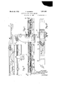
- Figure 1 is aside elevation of a punch machine equipped with a spacing device constructed according to my invention.
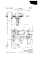
- Figure 2 is a plan View taken along line 2-2 of Figure 1.
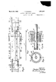
- Figure 3 shows a partial side elevation of a punch press equipped according to my invention, with parts broken away for clearer illustration of others, the scale being considerably larger than in Figure 1.
- Figure 4 is a partial front elevation of the structure shown in Figure 3, with parts broken away.
- Figure 5 is a rear elevation of the structure shown in Figures 3 and 4, with parts broken away.
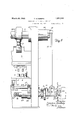
- Figure 6 is a detail view showing parts of the stop mechanism.
- Figure 7 is a detail plan view showing parts of the operating device for the rapid travel mechanism.
- Figure 8 is an elevation of the parts shown in Figure 7.
- Figure 9 is a detail view showing parts of thecarriage and track in elevation.
- Figure 10 is a detailplan view showing the stop strap and the parts of the stop mechanism.
- Figure 11 is a side view of the template or indicating device.
- Figure 12 is a sectional elevation of the clutch mechanism.
- Figure 13 shows a cross section taken alon the lines 1313 of Figure 12.
- the reference numeral 1 indicates the frame of a punch machine to which my invention is applied.
- the frame carries a vertically slidable head 2 upon which are mounted the punches 3.
- the punches are so constructed as to bevertically slidable in a body member 4, and this body member is provided. with a gag 5 having a handle by which it may be readilywithdrawn or interposed between the punch proper and a part of the body member 4.
- the bed 6 of the press carries suitable dies 7 mounted to receive their respective punches.
- the reciprocating head 2 is driven by a motor 8 through the main shaft 9 and connecting rods 10 of conventional construction.
- the head is shown in its lower position in Figure 4, and in its upper position in Figures 3 and 5.
- a track 11 extends through the machine in each direction to a distance somewhat greater than the length of the longest sheet of metal which is to be handled, and is provided with rollers 12 which support the longitudinal members 13 of the carriage.
- a buggy 14 is provided at each end of the carriage; These buggies are slidable along the upper flange 15 of the longitudinal members 13, and means (not shown) is provided for clamping the buggies in whatever position is required a nil to take a given length of sheet metal. Suitable clamps 16 are attached to the buggies for holding the sheet 17 in predetermined position with respect to the buggies and carrlage.
- the buggies are formed in two separate portions 125 and 126.
- the portion 125 is generally fixed at the end of the track and left there, while the portion 126 is adjusted along the track to suit each length of metal that is to be handled. This arrangement permits the use of the stop straps of the same length for different lengths of material.
- the members 126 are provided with a bracket 127 and a pin 128 which passes through allele in :the clamp 16, as shown, and thus forms a 'conven-ientrand readily removable fastening for the clanrp.
- the clamp is slidable longitudinally in the bracket 12? so that when one end of the sheet of metal :comes close lto the machine, the clamp at that end :may be :loosened, the pins 1-28 removed, and the bracket slid back out of the way of the punch and 'die. It will he understood that the clamps at the other ends of the sheet will still :hold it firmly in position with respect to the carriage. When that end of the sheet is finished rand :moved away from the dies, the clamps are xreattachedrand,
- the clamps at the other end may be removedandslidback voutof the way in the same manner;
- suit-able supports 18 are provided which (carry miles 1.19. Each anle narriesa plurality of spaced rollers 20. These xrollerszare freely rotatable on theiaxles, and are so arranged :that their upper periphery i-sttangent 110113119, plane in which the work is carried, and they serve as 'c'onvenient supports for the sheet as it is moved :ailong zthe tracks.
- the longitudinal members 1130f the carriage are provided with racks'2i1, A suitable geari22 is fixedito theshaft 23 which is mounted in the frame oi" the press, the arrangement being suchthat the carriage is operated by rotation of the shaft andgear.
- Another gear .24 is ifixedtothew shaft 23, and this is driven throngha-n iidler gear 25 by the gear 26.
- gear :26 ' is reta'tab'ly mounted on "the shalft27 which is carried by suitable 'bearin frame oifthe press as shown.
- a clutch housing 128 is secured to the gear 26, and its other end is rotatably carried on theisha'ft2 7 by-a cap member having a suitmember 29 :isslidable upon the shaft 127 andin i the housing 28, and the clutch is compressed against the shoulder of the shaft by a spring 36 which is carried between the collar 37 and the lock nuts 38.
- This arrangement provides an adjustable friction drive of the carriage from the shaft 27.
- the shaft'9 carries a head 39 upon which is mounted a crank 40.
- This crank is adjustable to any desired throw along the radial slot- 41 and may be readily fixed in position when adjusted.
- the slot 41 is formed in the head 39 at an angle to the line of the crank center of the cranks 135 substantially as shown so that the crank lags behind the cranks 135 and the upward pull of the crank on the connecting rod.
- the resulting travel of the carriage will begin on the upward stroke of the punch, after the punch isen- 'tirelyclear of the work, and will continue for a short period afterthe clamp has reached top "dead center and the punch is started on the downzstroke. It will, however, bestopped before the punch comes in contact with the work.
- the movement'of the crank 40 is such that the last part :of the movement of the carriage is comparatively slow so that any rebound will vbe taken up and the stops firmly pressed against the pawl to locate the carriage :in exact position.
- the crank carries a connecting rod 42 which is pivoted at its lower 'end to an arm 43.
- This'arm is rotatably mounted upon the shaft 2?, as shown, and carries, rig-idly mounted to rotate therewith, a crank 44.
- the arm 43 is longer than the maximum radius of travel of the crank 40, so that the crank 43 only reciprocates through an arc and does :not complete a revolution.
- Rigidly keyed to the'shaft 27 ' is aratchet wheel 45, and'this ratchet is operated in one direction only by the-crank 44 through a pawl 46 which is resiliently held in position bya'spring 47.
- An auxiliary means of operating the shaft 27 includes a. motor 48 controlled by switch 49, a worm shaft 50, and a worm gear .diagrammatically indicated at 51 and52.
- the gear 52 is rotatably mounted on the shaft 27, but has a recess 53 to receive the pawl of clutch 54, as shown.
- the clutch is keyed to the shaft 27, but is slidable thereon by means of a lever '55 which is pivoted to the clutch at 56 and to a rigid support 57 at 58. By moving the lever to the right, as shown in Figure 5,0r toward'the observer, as shown in Figures 3 and 8, the clutch 54 may be engaged with the'worm gear, and by operating the switch 49 the carriage may (be rapidly moved in either direction.
- a trip lever 59 is pivoted to the frame at 60 and operates through a link 61 to lift the cam 62 which is pivoted to a fixed support at 6-3.
- the cam 62 is bent to substantially follow the upper periphery of the ratchet wheel 45, as shown, and when the trip lever is in its upper position, as shown, the operation of the pawl 46 is not interfered with;
- the lever 55 is provided with a rod 66 which carries a block 67 to interlock with the lever 59. Unless the lever 55 is moved toward the machine to entirely disengage the clutch, the lever 59 will rest on top of the block 67, thus preventing the operation of the ratchet and leaving the pawl free to rotatein either direction. When the lever 59 is in position to permit the pawl 46 to engage the ratchet teeth, the lever 55 can not be pulled to engage the clutch 54.
- a suitable block 69 is carried by the stationary portion 125 of the buggies for the attachment of a cam strap 70.
- This cam strap may comprise a shipbuilders channel member of length somewhat greater than that of the sheet to be worked on; preferably all straps for the same machine are the same length.
- a number of longitudinal rows of holes 71 are drilled in the channel member; I have shown five rows of holes, which is usually suflicient, but it is obvious that any number of rows might be used.
- the stops 72 may be attached at any desired point along the length of the strap.
- the holes are not located in the center of the stop, but are closer to one end then the other so that avery close adjustment of the position of the stop maybe had by selecting a hole in a different row or by reversing the stop without making a special stop to get the exact position.
- Suitable bolt holes 74 and dowel. holes 75 are provided at the end of the strap 70 so that it may be conveniently attached to or detached from the buggies in the same position.
- bracket 76 Fixed to the bed 6 of the machine is rigidly constructed bracket 76 which is shown in Figures 6, 4, and 10.
- This bracket carries a. transverse shaft 77 mounted in a slotted hole 78.
- the hole is slightly oblong in a horizontal direction to permit a slight movement of the shaft 77 in the direction of travel of the carriage and the cam strap 70.
- the shaft 77 is provided with a screw 79 at each end having a head which snugly fits a bore 80 in the side wall 81 of the member 76.
- the screw 79 prevents the rotation of the shaft 77, and serves as a seat for one end of the compression coil spring 82 which is retained by the screw plug 83, as shown in Figure 6.
- the contacting surfaces of the lugs 85 and the stops 72 are on a line substantially tangent to a circle drawn with the shaft 77 as the center, as shown at 86, so that when the stop is forced abruptly against the dog, there will be no tendency for the dog to slide over the stop, while the dog may be raised out of contact with the stop without any backward movement of the carriage.
- a transverse shaft 87 is mounted in the walls 81 of the member 76.
- This shaft carries an arm 88, by means of which it is operated, and which is keyed to it, as at 89.
- Another arm 90 also mounted to rotate with the shaft 87 is provided with a cross member 91 which extends over the rear ends of the dogs 84 so that when the shaft 87 is rocked to the right, as shown in Figure 6, the lugs 85 will be lifted out of the way of the stops 72.
- a shaft92 is also mounted in one wall 81 of the member 76 and carries a forked arm 93 keyed to it by means of key 94.
- the fork 95 V of the arm 93 straddles a point 96 onthe arm 88. It will be seen that the rotation of the shaft 92 in an anti-clockwise direction will rotate the shaft 87 clockwise and lift the lugs 85.
- the shaft 92 extends to a bracket 97 and has rigidly fixed to it a gear 98 by means of which it may be rotated.
- Slidably mounted in the bracket 97 is a rack 99 which is normally held in upward position by a spring 100.
- the lower end of the spring is supported by a bracket 101 mounted on the frame.
- the rack 99 has an extension 102 which is adapted to be engaged by a member or plunger 103 which is carried by the reciprocating head of the punch.
- the extension is provided with a pin 104, as shown in Figures 3 and4.
- a lever 105 is pivoted to the bracket 97 at 106, and has a recessed hook portion 107 to receive the pin 104 so that the rack 99 may be retained in its lower position when desired.
- a bracket 108 is mounted on the head 2, as shown in Figures 3 and 4..
- This bracket carries the rod 103, which is slidably mounted therein, in alignment with the extension 102,
- the mem- I her 112 can be moved into or out of the path of the rod 103, thus forming a gag and causing the operation of the rack 99 by the downward movement of the punch only when the gag is in position.
- FIG. 2 and 11 A preferred form of indicating device 115 is shown in Figures 2 and 11.
- This constitutes a template strip, preferably of wood or other light material, having a. hook 116 attached to one end, by means of which it may be conveniently located along the sheet of metal which is being worked on.
- a pointer 117 is carried along a bracket 118 on the head 2. This pointer is mounted in a position where it may be conveniently observed by the operator. It is freely slidable in the bracket and has a head 119 so that it will be lifted upon the upward movement of the head 2, but will not be forced into the template on downward movement of the head.
- the template 115 is provided with graduations 120 at such points as are adjacent to the indicator when the carriage is in positionto punch the corresponding hole or holes. Each punch is marked with a letter, and each graduation on the gage is marked with a letter, or letters, corresponding to the letterson the punches which are to operate when the indicator points to that graduation. 4
- FIG 2 I have shown a sheet of metal requiring a number of holes to be punched.
- the punch 7 A has punched the hole 121 and is to punch the holes indicated at 122.
- the punch 75 is to punch the holes indicated at 123, and the punches 7C, 71), 7E, and 7F punch the holes indicated as being in line with them. hen a graduation comes under the indicator, the operator pulls all the gags, except those indicated by the letters appear ing at that graduation, and when the head 2 is operated, the proper holes will be punched.
- the buggies 14, carrying the clamps 16, are adjusted to the proper length to receive the sheets which are to be worked on.
- the sheet diagrammatically illustrated at 17 is placed in horizontal position on top of the rollers 20, and the clamps 16 are attached.
- the gage 115 is placed on top of the sheet with the hook 116 at one end to J locate the gage with respect to the sheet.
- the operator will note that the indicator 117 points to a graduation 120 on the gage, and he will move such gags into position as are indicated by the letters at the graduation, and the corresponding holes will be punched upon the first down stroke of the slide 2. It will be understood that the machine is provided with the usual means for stopping the shaft 9 at the end of each revolution, if desired, but that in ordinary operation this shaft is permitted to continuously rotate.
- the arrangement ofthecrank is such that themovement of the ratchet wheel occurs during aportion of tlieqrevolutien of the shaft-9 subsequent to the withdrawal of the punch 3 from the work and terminating jus'ta'fter thehighest-point in the stroke of the punch. This-is necessary so thatthe carriage will be moved only at such times, as the punches clear the work. Due to this arrange-ment,'the plunger 103rises out of contact with the extension 102 before any movement of'the'carriagehas occurred, and the pawls would ordinarily drop into position in front of the same stop thuspreventing any movement of the carriage upon the subsequent stroke.
- the lever 105 may then be shifted to cause the hook-l07 to engage the pin 104, thus holding the pawls' secureto the stops 72'.
- a track a carriage movable along the track, intermittently operating yie-l'clable means for moving the carriage, a'longitudinal strap attachedto the carriage, a plurality ofstops attached; tothe strap, an abutment at a point along. the track f to engage the stops during movement of the carriage to temporarily prevent further movement thereof, and means operable'bya part of-the machine tor-disengaging the a butm'ent from thestop.
- a track a carriage :movable'along said'track, a longitudinal'strap carried by the carriage, a plurality of longitudinally spaced stops mounted on said strap,.
- a pivoted abutment fixed-at-a point along said trackandarranged to swingi'nto or out'ofthe path of said: stops, frictional means for moving said carriage along said track to firmly: press one-of said stopsiagainstsaid abutment, and means-to swing saidxabutmenh out of 'thepath of" said stop ateachoperation of the machine.
- control means embodying a device for positively preventing simultaneous operation of said connection and said independent means.
- a movable carriage a plurality of stops carried by said carriage, a pivoted abutment fixed to said machine and arranged to swing into or out of the path of said stops, means normally holding the abutment in the path of the stops, said stopsbeing adapted to engage the abutment duringmovement of said carriage and means carried by a part of the machine to contact with the abutment and swing it out of the path of said stops.
- a movable carriage a plurality of stops mount ed on said carriage, an abutment adapted to be interposed in the path of said stops, means for normally holding said abutment in said path, said stops being adapted to contact with said abutment during movement of said carriage to prevent further movement thereof, a reciprocating tool, and means connected with the tool and operable at each reciprocation thereof to displace said abutment.
- a track a carriage movable along this track, frictional means to move the carriage, a plurality of longitudinally spaced stops along the carriage, an abutment at a point along the track and adapted to engage the stops, said stops displacing said abutment a fixed distance at each operation, irrespective of variations in the spacing of said stops and means to disengage the abutment and the stops.
- a track a carriage movable along said track, a punch, frictional means operated by the punch operating means to advance the carriage a predetermined distance along the track, a longitudinal strap carried by the carriage, a plurality of rows of stops mounted on said strap, an abutment mounted on a pivot fixed to the bed of the machine and lying in the path of each row of stops, said stops being adapted to contact with said abutments to temporarily prevent further movement of the carriage and means operated by the machine for swinging said abutments out of the path of said stops.
- a track In a machine of the class described, a track, a carriage movable along said track, a punch, operating means for said punch,
- frictional means operated by the punch operating means to advance the carriage a predetermined distance along the track, a longitudinal strap carried by the carriage, a plurality of rows of stops mounted on said strap, an abutment mounted on a pivot fixed with respect to the track and lying in the path of each row of stops, and means including a plurality of levers operable by a movement ofthe punch to disengage said abutment from said stops.
- a track a carriagemovable along said track, a punch, operating means for said punch, frictional means operated by the punch op erating means to advance the carriagea predetermined distance along the track, a longitudinal strap carried by the carriage, a plurality of longitudinal rows of stops mounted on said strap, a plurality of abutments mounted on a pivot fixed with respect to the track, each abutment lying in the path of a row of stops, and means including a rack and pinion operated by a movement of the punch for moving said abutments out of the path of said stops.
- a punch machine a work carriage, a plurality of stops mounted in predetermined positions on said carriage, a punch, means including a rotatable shaft for operating said punch, a crank on said shaft, a connecting rod having an end mounted on said crank, a ratchet operated by said connecting rod, means including a friction clutch for driving said carriage from said ratchet, a pivoted abutment mounted at a fixed point on said machine and arranged to swing into or out of the path of the stops, a lever for swinging said abutment on its pivot, a gear connected to operate said lever, a slidable rack engaged with said gear, resilient means for moving said rack in one direction, and means carried with said punch for contacting with said rack to move it against the said resilient means and thereby swing the abutment on its pivot.
- a frame a reciprocating tool carried by said frame, a carriage movable with respect to said frame, frictionally operated means to intermittently move the carriage, positive stop mechanism for arresting the movement of said carriage at predetermined points, thereby causing slippage of said frictional means, a slidable member carried by the tool, a gag adapted to be interposed in the path of said slidable member to force it to move with thereciprocating tool, and means carried on the frame of said machine and arranged to be operated by forcible movement of said slidable member to disengage said stop mechanism.
- a movable carriage a device operable by a part of said machine for intermittently moving said carriage, a rapid travel device operable by another part of said machine to move said car'iage in either of two dire:- tions, and means including a pair of interlocking levers to prevent the simultaneous operation of both of said devices.
- a movable carriage, a ratchet and pawl device operable by a part of the machine for intermittently moving said carriage, a rapid travel device for moving said carriage independently of the movement of said first de vice, and means to prevent the operation of said rapid travel device while said pawl is in position to engage the ratchet.
- a movable carriage a device for intermittently moving said carriage, a rapid travel device for moving said carriage independently of said first device, a clutch for controlling said rapid travel device, means for disconnecting said first named device from the carriage, and means for preventing the reconnection of said means while said clutch is engaged.
- a work carriage In a sheet metal punching machine, a work carriage, a track for said carriage, frictional means for moving said carriage along said track, a punch, a plurality of longitudinally spaced stops fixed to the carriage, an abutment fixed to the machine in the path of said stops, means operated during-a part of each stroke of the punch for operating said frictional means, means operated during another part of the stroke of the punch for removing said abutment from the path of said stops, means for releasing said abutment, and means operative upon the release of said abutment to prevent its re-engagement prior to the next movement of the carriage.
- a working tool In a machine of the class described, a working tool, a work carriage, a track for said carriage, frictional means connected with said working tool for moving said carriagealong said track during a part only of the cycle of operation of said tool, a plurality of stops attached to said carriage, an
- abutment carried at a fixed point on the track, means movable between operations of the friction means to disengage the stops from the abutment, means to withdraw said disengaging means before the subsequent operation of the friction means, and means to prevent the re-engagement' of the abutment with the same stop upon the withdrawal of the disengaging means.
- a work carriage a clamp adapted to be attached to the work, a bracket mounted on the carriage and arranged to slidably receive the clamp, registering holes in said bracket and said clamp, and a pin adapted to be passed through said holesto accurately locate the clamp with respect to the carriage.
- a stop mechanism a movable member having a plurality of longitudinally spaced blocks mounted thereon, pivoted abutments normally held in the path of said stops, intermittently operated means for moving said member, means operated only between operations of said intermittently operating means to shift the abutments out of the path of said stops, and resilient means to shift the abutments in a direction opposite to the movement of said first named member as soon as the abutments are clear of the stops, whereby the re-engagement of an abutment with the same stop will be prevented.
- a stop mechanism a bracket, an elongated member carrying a plurality of longitudinally spaced stops and movable through said bracket, a transverse slotted bore in said bracket, a pivot shaft mounted in said slotted bore, yieldable means for moving said shaft to one side of said slot in a direction opposite to the movement of said elongated member, an abutment rotatably mounted on said shaft and arranged to swing into or out of the path of said stops, means for normally holding the said abutment in position to engage the stop, said yieldable means being adapted to be displaced upon contact of a stop with the abutment, whereby the shaft will be forced against the opposite side of the slot, and means for swinging the abutment out of the path of said stop, whereby the longitudinal member may be moved to the next stop.
- a bracket a transverse bore in said bracket, a shaft loosely fitting said bore, resilientmeans urging said shaft against one side of said bore, a member rotatably mounted on said shaft, a lug at one end of said pivoted member comprising an abutment, a longitudinally movable block adapted to engage said abutment, and means to lift said lug out of contact with said block.
- a stop mechanism a bracket, a transverse bore in said bracket, a shaft loosely fitting said bore, resilient means urging said shaft against one side of the bore, a member movable with respect to said bracket and carrying a. plurality of longitudinally spaced stops, a pivoted member mounted on said shaft and having a lug at one end comprising an abutment to engage said stops, disengaging means for swinging the pivoted member to disengage the lug from the stop, said resilient means operative upon disengagement of the lug from the stop to move the shaft toward the stop, whereby, upon tl e release of the disengaging means, the lug will catch on top of the stop instead of dropping in front of it.
- a stop mechanism a bracket, a transverse bore in said bracket, a shaft mounted in said bore, a member longitudinally movable with respect to said bracket, a plurality of stops carried by said member, a member pivoted to said shaft and comprising an abutment for engaging said stops, disengaging means for moving said abutment out of the path ofsaid stops, and means for preventing the re-engagement of said stops with said abutment upon the withdrawal of said disengaging means.
- a stop mechanism a bracket, a member longitudinally movable with respect to said bracket,,a transverse shaft mounted on said bracket, a plurality of stops carried by Said longitudinally movable member, a pivoted abutment carried by said shaft and adapted to engage said stops, the engaging surfaces of said abutment and said stops be ing in a plane substantially tangent to a circle drawnthrough the point of contact and having the shaft as a center.
- a stop mechanism a bracket, a mem ber longitudinally movable with respect to said bracket, a plurality of rows of stops carriedby said longitudinally movable member, a plurality of pivoted abutments carried by the bracket, onein the path of each row of stops, a rock shaft carried by said bracket, a lever carried by said rock shaft, said lever being arranged to disengage all the abutments upon operation ofthe rock shaft.
- a work carriage In a metal working machine, a work carriage, a plurality of stops mounted on said. carriage, a reciprocating head, a pivoted abutment mounted on said machine and arranged to be swung into or out of the path of said stops, a lever for operating said pivoted a utment, a gear for operating said lever and a rack operated by said head and engaging said gear.
- a work carriage In a metal working machine, a work carriage, a plurality of stops mounted on said carriage, a reciprocating head, an abutment pivoted on said machine and arranged to be swung into and out of the path of said stops, a reciprocating member operatively connected to said abutment, a plunger on said head to engage said reciprocating member and means for rendering said plunger effective or ineliective to operate said reciprocating member.
- a work carriage In a metal working machine, a work carriage, a plurality of stops mounted on said carriage, a reciprocating head, an abutment pivoted on said machine and arranged to be swung into and out of the path of said stops, a rack operatively connected to said abutment, a plunger slidably mounted on said head to engage said rack and means for rendering said plunger efi'ective or ineifective to operate said rack.
- a bracket In a punching mechanism, a bracket, a shaft movably mounted in said bracket, a member longitudinally movable with respect to said. bracket, a plurality of stops carried by said member, an abutment for said stops pivoted on said shaft, means for disengaging said abutment from said stops and means shifting said shaft at each disengagement from astop to prevent reengagement of said abutment with the stop then disengaged.
- a punching mechanism a work carriage, stops car ied by said work carriage, an abutment for said stops, means for disengagin said abutment from said stops and means bodily shifting said abutment at each disengagement of said abutment from a stop to prevent reengagement of said abutment with the stop then disengaged, said shifting means yielding upon engagement of said abutment with each stop to permit movement of said abutment to a predetermined position.
- a punching mechanism a work carriage, stops carried by said work carriage, an abutment-for said stops, meansffor disengaging said abutment from said stops and resilient means bodily shifting said abutment at each disengagement of said abutment from a stop to prevent reengagement of said abutment with the stop then disengaged.
- the combi- H nation of a movable carriage uniformly driven means including a ratchet and a friction clutch driven by said ratchet for moving said carriage, a plurality of stops movable with said carriage, means comprising abutments mounted in a bracket on said machine for engaging said stops and stopping said carriage.
- a movable carriage uniformly driven means including a ratchet and a friction clutch for moving said carriage, a plurality of stops moving with said carriage and adapted to be variously set according to the work to be done, and means comprising abutments arranged in the paths of said stops for stopping said carriage.
- a movable carriage uniformly driven means including a ratchet and a friction clutch for moving said carriage, a plurality of stops movable with said carriage, means comprising abutments mounted in a stationary bracket for stopping said carriage independently of the carriage moving means.
- a movable carriage uniformly driven means including a ratchet and a friction clutch connected in series for moving said carriage, a plurality of stops movable with said carriage, means comprising abutments supported in fixed relation to said machine for stopping said carriage independently of the carriage moving means.
- a movable carriage uniformly operated means for moving said carriage, a plurality of stops movable with said carriage, said stops being arranged to be variably set according to the work to be done, abutments arranged in the paths of said stops adapted to stop the carriage on engagement with said stops, and means for taking up any rebound after such positive stoppage.
- a work positioning device comprising a carriage, uniformly driven means including a ratchet and a friction clutch for moving said carriage, a
- stops movable with said carriage, said stops being arranged in various -positions according to the work to be done, abutments arranged in the path of said stops adapted to stop the carriage on engagement with said stops, and means operated by the machine for disengaging said stops and abutments.
- a work positioning device comprising a carriage, means operated in uniform steps for driving said carriage, a plurality of stops moving with said carriage, said stops being arranged in various positions according to the work to be done, abutments arranged in the path of said stops adapted to stop the carriage on engagement with said stops, means for taking up any rebound after the engagement of such stops and abutments, means operated by the machinefor disengaging said stops, and abutments and means for preventing the re-engagement of the stops and abutments.
- a movable carriage, uniformly driven means including a friction clutch for moving said carriage, a plurality of longitudinal rows of stops mounted on said car,- riage, means for stopping said carriage independently of said moving means comprising a plurality of abutments pivotally mounted in a bracket stationary in respect to said carriage and adapted to engage said stops.
- a movable carriage In a metal working machine, the combination of a movable carriage, driving means for said carriage adapted tobe operated in uniform steps, a plurality of stops carried by said carriage arranged in a plurality of parallel rows, a plurality of abutments, one for each row, adapted to engage said stops, and means comprising a friction clutch interposed between said driving means and said carriage adapted to yield when said abutments and stops are in engagement.
Landscapes
- Engineering & Computer Science (AREA)
- Mechanical Engineering (AREA)
- Press Drives And Press Lines (AREA)
Description
March 29, 1932. KASEBERG 1,851,845
STRUCTURAL STEEL WORKING MACHINE Filed Feb. 20, 1929 6 Sheets-Sheet l 726040219 (aseiery m March 29, 1932 T. KASEBERG 1,851,845
STRUCTURAL STEEL WORKING MACHINE Filed Feb. 20} 1929 6 sheets-sheet 3 //V VA A/ 70/? Tlzeodare fi aseiery March 29, 1932. T KAS EBERG STRUCTURAL STEEL WORKING MACHINE 6 Shecs-Sheet 4 Filed Feb. 20, 1929 R H w& M Z 0 Va. W K w 8 W. 4
I March 29, 1932. T. KASEBERG 1,851,845
STRUCTURAL STEEL WORKING MACHINE Filed Feb. 20, 1929 6 Sheets-Sheet 5 March 29, T KAS G STRUCTURAL STEEL WORKING MACHINE Filed Feb. 20, 1929 6 Sheets-Sheet 6 I w A 1 A 97 fa l r1 v f6 5f @LQ o s nwavraxe Teodore @583?? 5r Patented Mar. 29, 1932 UNITED STATES PATENT OFFICET THEODORE KASEBERG, OF. GRANITE CITY, ILLINOIS, ASSIGNOR TO THE AMERICAN CAR AND FOUNDRY COMPANY, OF NEW YORK, N. Y., A CORPORATION OF NEW JERSEY STRUCTURAL STEEL WORKING MACHINE Application filed February 20, 1929. Serial No. 341,299.
This'invention relates to structural steel Working machines and particularly to machines for punching rivet holes in large steel members, such as are used in the fabrication of freight cars, bridges, and other structural steel work. In machines of this kind, it is customary to attach the sheet of steel which is to be punched, to a horizontal traveling carriage, which is arranged to pass between the punches and the dies of a large punch press. Ordinarily, a large number of holes are to be punched in the sheet at spaced intervals along its length, and to this end punches are mounted in the punch press in line longitudinally'with each hole which is to be punched, and when the carriage is moved into position so that the location of the hole is in line with the punch, the gag for that v punch is interposed, and the press is operated.
Where a number of pieces of the same kind are to be made, it is desirable to provide some means for rapidly and accurately moving the carriage into position for punching each successive hole or holes, and also to provide some means for indicating to the operator which of the gags to pull and which to interose. p One of the objects of this invention is to provide a simple and inpensive device for the above described purpose. Other objects will appear from the following specification and the accompanying drawings, in which:
Figure 1 is aside elevation of a punch machine equipped with a spacing device constructed according to my invention.
Figure 2 is a plan View taken along line 2-2 of Figure 1.
Figure 3 shows a partial side elevation of a punch press equipped according to my invention, with parts broken away for clearer illustration of others, the scale being considerably larger than in Figure 1.
Figure 4 is a partial front elevation of the structure shown in Figure 3, with parts broken away.
Figure 5 is a rear elevation of the structure shown in Figures 3 and 4, with parts broken away.
Figure 6 is a detail view showing parts of the stop mechanism.
Figure 7 is a detail plan view showing parts of the operating device for the rapid travel mechanism. I
Figure 8 is an elevation of the parts shown in Figure 7.
Figure 9 is a detail view showing parts of thecarriage and track in elevation.
Figure 10 is a detailplan view showing the stop strap and the parts of the stop mechanism.
Figure 11 is a side view of the template or indicating device.
Figure 12 is a sectional elevation of the clutch mechanism.
Figure 13 shows a cross section taken alon the lines 1313 of Figure 12.
The reference numeral 1 indicates the frame of a punch machine to which my invention is applied. The frame carries a vertically slidable head 2 upon which are mounted the punches 3. The punches are so constructed as to bevertically slidable in a body member 4, and this body member is provided. with a gag 5 having a handle by which it may be readilywithdrawn or interposed between the punch proper and a part of the body member 4. By this arrangement, when the head 2 comes down, the punch may simply slide in the body member when the gag is withdrawn, but will punch a hole in the metal when the gag is interposed,
The bed 6 of the press carries suitable dies 7 mounted to receive their respective punches. The reciprocating head 2 is driven by a motor 8 through the main shaft 9 and connecting rods 10 of conventional construction. The head is shown in its lower position in Figure 4, and in its upper position in Figures 3 and 5.
A track 11 extends through the machine in each direction to a distance somewhat greater than the length of the longest sheet of metal which is to be handled, and is provided with rollers 12 which support the longitudinal members 13 of the carriage. At each end of the carriage,a buggy 14 is provided; These buggies are slidable along the upper flange 15 of the longitudinal members 13, and means (not shown) is provided for clamping the buggies in whatever position is required a nil to take a given length of sheet metal. Suitable clamps 16 are attached to the buggies for holding the sheet 17 in predetermined position with respect to the buggies and carrlage.
The buggies are formed in two separate portions 125 and 126. The portion 125 is generally fixed at the end of the track and left there, while the portion 126 is adjusted along the track to suit each length of metal that is to be handled. This arrangement permits the use of the stop straps of the same length for different lengths of material.
The members 126 are provided with a bracket 127 and a pin 128 which passes through allele in :the clamp 16, as shown, and thus forms a 'conven-ientrand readily removable fastening for the clanrp. The clamp is slidable longitudinally in the bracket 12? so that when one end of the sheet of metal :comes close lto the machine, the clamp at that end :may be :loosened, the pins 1-28 removed, and the bracket slid back out of the way of the punch and 'die. It will he understood that the clamps at the other ends of the sheet will still :hold it firmly in position with respect to the carriage. When that end of the sheet is finished rand :moved away from the dies, the clamps are xreattachedrand,
*when desired, the clamps at the other endmay be removedandslidback voutof the way in the same manner;
Along the track, suit-able supports 18 are provided which (carry miles 1.19. Each anle narriesa plurality of spaced rollers 20. These xrollerszare freely rotatable on theiaxles, and are so arranged :that their upper periphery i-sttangent 110113119, plane in which the work is carried, and they serve as 'c'onvenient supports for the sheet as it is moved :ailong zthe tracks.
The longitudinal members 1130f the carriage are provided with racks'2i1, A suitable geari22 is fixedito theshaft 23 which is mounted in the frame oi" the press, the arrangement being suchthat the carriage is operated by rotation of the shaft andgear. Another gear .24 is ifixedtothew shaft 23, and this is driven throngha-n iidler gear 25 by the gear 26. The
gear :26 'is reta'tab'ly mounted on "the shalft27 which is carried by suitable 'bearin frame oifthe press as shown.
A clutch housing 128 is secured to the gear 26, and its other end is rotatably carried on theisha'ft2 7 by-a cap member having a suitmember 29 :isslidable upon the shaft 127 andin i the housing 28, and the clutch is compressed against the shoulder of the shaft by a spring 36 which is carried between the collar 37 and the lock nuts 38. This arrangement provides an adjustable friction drive of the carriage from the shaft 27.
' The shaft'9 carries a head 39 upon which is mounted a crank 40. This crank is adjustable to any desired throw along the radial slot- 41 and may be readily fixed in position when adjusted. The slot 41 is formed in the head 39 at an angle to the line of the crank center of the cranks 135 substantially as shown so that the crank lags behind the cranks 135 and the upward pull of the crank on the connecting rod. The resulting travel of the carriage will begin on the upward stroke of the punch, after the punch isen- 'tirelyclear of the work, and will continue for a short period afterthe clamp has reached top "dead center and the punch is started on the downzstroke. It will, however, bestopped before the punch comes in contact with the work. It will be noted that the movement'of the crank 40 is such that the last part :of the movement of the carriage is comparatively slow so that any rebound will vbe taken up and the stops firmly pressed against the pawl to locate the carriage :in exact position.
The crank carries a connecting rod 42 which is pivoted at its lower 'end to an arm 43. This'arm, is rotatably mounted upon the shaft 2?, as shown, and carries, rig-idly mounted to rotate therewith, a crank 44. The arm 43 is longer than the maximum radius of travel of the crank 40, so that the crank 43 only reciprocates through an arc and does :not complete a revolution. Rigidly keyed to the'shaft 27 'is aratchet wheel 45, and'this ratchet is operated in one direction only by the-crank 44 through a pawl 46 which is resiliently held in position bya'spring 47.
An auxiliary means of operating the shaft 27 includes a. motor 48 controlled by switch 49, a worm shaft 50, and a worm gear .diagrammatically indicated at 51 and52. The gear 52 is rotatably mounted on the shaft 27, but has a recess 53 to receive the pawl of clutch 54, as shown. The clutch is keyed to the shaft 27, but is slidable thereon by means of a lever '55 which is pivoted to the clutch at 56 and to a rigid support 57 at 58. By moving the lever to the right, as shown in Figure 5,0r toward'the observer, as shown inFigures 3 and 8, the clutch 54 may be engaged with the'worm gear, and by operating the switch 49 the carriage may (be rapidly moved in either direction.
A trip lever 59 is pivoted to the frame at 60 and operates through a link 61 to lift the cam 62 which is pivoted to a fixed support at 6-3. 'The cam 62 is bent to substantially follow the upper periphery of the ratchet wheel 45, as shown, and when the trip lever is in its upper position, as shown, the operation of the pawl 46 is not interfered with;
but when the pedal of the lever is moved downward, the cam 62 is raised above the points of the teeth 64 in the ratchet Wheel, as shown by the dotted line 65 in Figure 8. In this position the cam 62 will engage the roller 68 which is carried by the pawl, and the pawl will be lifted out of engagement with the ratchet teeth 64.
The lever 55 is provided with a rod 66 which carries a block 67 to interlock with the lever 59. Unless the lever 55 is moved toward the machine to entirely disengage the clutch, the lever 59 will rest on top of the block 67, thus preventing the operation of the ratchet and leaving the pawl free to rotatein either direction. When the lever 59 is in position to permit the pawl 46 to engage the ratchet teeth, the lever 55 can not be pulled to engage the clutch 54.
A suitable block 69 is carried by the stationary portion 125 of the buggies for the attachment of a cam strap 70. This cam strap may comprise a shipbuilders channel member of length somewhat greater than that of the sheet to be worked on; preferably all straps for the same machine are the same length.
A number of longitudinal rows of holes 71 are drilled in the channel member; I have shown five rows of holes, which is usually suflicient, but it is obvious that any number of rows might be used. By means of these holes and screws 73, the stops 72 may be attached at any desired point along the length of the strap.
The holes are not located in the center of the stop, but are closer to one end then the other so that avery close adjustment of the position of the stop maybe had by selecting a hole in a different row or by reversing the stop without making a special stop to get the exact position. Suitable bolt holes 74 and dowel. holes 75 are provided at the end of the strap 70 so that it may be conveniently attached to or detached from the buggies in the same position. I
Fixed to the bed 6 of the machine is rigidly constructed bracket 76 which is shown in Figures 6, 4, and 10. This bracket carries a. transverse shaft 77 mounted in a slotted hole 78. The hole is slightly oblong in a horizontal direction to permit a slight movement of the shaft 77 in the direction of travel of the carriage and the cam strap 70. The shaft 77 is provided with a screw 79 at each end having a head which snugly fits a bore 80 in the side wall 81 of the member 76. The screw 79 prevents the rotation of the shaft 77, and serves as a seat for one end of the compression coil spring 82 which is retained by the screw plug 83, as shown in Figure 6. One or more dogs or abutmcnts 84 rotatably mounted on the shaft 77, one dog for each row of holes 71 and stops 73 in the stop strap i 70 which passes through the bracket 7 6 under the pawls, as shown in Figures 4 and 6. The pawlsare made of hardened tool steel, as are the stops 72, and havelugs 85 at one end to lie in the path of and form an obstruction to the stops 7 2. The contacting surfaces of the lugs 85 and the stops 72 are on a line substantially tangent to a circle drawn with the shaft 77 as the center, as shown at 86, so that when the stop is forced abruptly against the dog, there will be no tendency for the dog to slide over the stop, while the dog may be raised out of contact with the stop without any backward movement of the carriage.
A transverse shaft 87 is mounted in the walls 81 of the member 76. This shaft carries an arm 88, by means of which it is operated, and which is keyed to it, as at 89. Another arm 90 also mounted to rotate with the shaft 87 is provided with a cross member 91 which extends over the rear ends of the dogs 84 so that when the shaft 87 is rocked to the right, as shown in Figure 6, the lugs 85 will be lifted out of the way of the stops 72.
A shaft92 is also mounted in one wall 81 of the member 76 and carries a forked arm 93 keyed to it by means of key 94. The fork 95 V of the arm 93 straddles a point 96 onthe arm 88. It will be seen that the rotation of the shaft 92 in an anti-clockwise direction will rotate the shaft 87 clockwise and lift the lugs 85. The shaft 92 extends to a bracket 97 and has rigidly fixed to it a gear 98 by means of which it may be rotated. Slidably mounted in the bracket 97 is a rack 99 which is normally held in upward position by a spring 100. The lower end of the spring is supported by a bracket 101 mounted on the frame. The rack 99 has an extension 102 which is adapted to be engaged by a member or plunger 103 which is carried by the reciprocating head of the punch. The extension is provided with a pin 104, as shown in Figures 3 and4. A lever 105 is pivoted to the bracket 97 at 106, and has a recessed hook portion 107 to receive the pin 104 so that the rack 99 may be retained in its lower position when desired.
A bracket 108 is mounted on the head 2, as shown in Figures 3 and 4.. This bracket carries the rod 103, which is slidably mounted therein, in alignment with the extension 102,
so upon downward movement of the head 2.
110, and by means of this connection the mem- I her 112 can be moved into or out of the path of the rod 103, thus forming a gag and causing the operation of the rack 99 by the downward movement of the punch only when the gag is in position.
A preferred form of indicating device 115 is shown in Figures 2 and 11. This constitutes a template strip, preferably of wood or other light material, having a. hook 116 attached to one end, by means of which it may be conveniently located along the sheet of metal which is being worked on. A pointer 117 is carried along a bracket 118 on the head 2. This pointer is mounted in a position where it may be conveniently observed by the operator. It is freely slidable in the bracket and has a head 119 so that it will be lifted upon the upward movement of the head 2, but will not be forced into the template on downward movement of the head. The template 115 is provided with graduations 120 at such points as are adjacent to the indicator when the carriage is in positionto punch the corresponding hole or holes. Each punch is marked with a letter, and each graduation on the gage is marked with a letter, or letters, corresponding to the letterson the punches which are to operate when the indicator points to that graduation. 4
In Figure 2, I have shown a sheet of metal requiring a number of holes to be punched. The punch 7 A has punched the hole 121 and is to punch the holes indicated at 122. The punch 75 is to punch the holes indicated at 123, and the punches 7C, 71), 7E, and 7F punch the holes indicated as being in line with them. hen a graduation comes under the indicator, the operator pulls all the gags, except those indicated by the letters appear ing at that graduation, and when the head 2 is operated, the proper holes will be punched.
In operation, the buggies 14, carrying the clamps 16, are adjusted to the proper length to receive the sheets which are to be worked on. The sheet diagrammatically illustrated at 17 is placed in horizontal position on top of the rollers 20, and the clamps 16 are attached. The gage 115 is placed on top of the sheet with the hook 116 at one end to J locate the gage with respect to the sheet.
It will be understood that the loading of the carriage is done at the left end of the machine, as shown in Figure 2. The stops 72 having been placed on the strap 70 in proper position, the clutch 5 1 is engaged and the rapid travel motor a8 started in order to bring the sheet up'close to the punch. When the location of the first hole is approached, the motor 48 is stopped, the clutch 54 is disengaged, and the motor 8 is started; this motor being connected by means of suitable gears to the shaft 9 rotates the shaft, reciproeating the slide 2 and rotating the head 39, which carries the crank 40. This reciprocates with connecting rod 12 and the cranks 43 and 44; the pawl46 now being in position, the ratchet wheel is intermittently rotated and with it the shaft 27. This shaft, operated through the clutch, drives the gear 26 which,
in turn, operates the gears 25, 24, and 22, the
last of which operates the table. It'will be noted that the arrangement of gears is such as to move the carriage to the right, as shown. in Figures 1, 2, and 3.
This intermittent movement of the carriage continues until the first stop 72 comes in contact with the lug 85 of one of the pawls 84, and then continues for approximately one-sixteenth of an inch until the shaft 7 7 is moved across the slot 78 against the comparatively weak spring 82 and firmly seated at the rear of the slot. Further movement of the strap 7 0 being impossible, the whole carriage is stopped and the clutch 28 begins to slip, permitting the completion of the stroke of the arm 44 and ratchet wheel. The contact of the lug 85 and stop 72 positively locates the longitudinal position of the carriage with respect to the punches, and the carriage is now in position for punching the first hole, or holes.
An important factor of the invention is that if the carriage should strike the pawl 84 so hard as to rebound, the subsequent movement of the clutch will be ample to take up the rebound more slowly and press the stop 7 2 against the lug 85 firmly before the stroke is finished. As the punch which is carried by the reciprocating head approaches the work on its downward stroke, the connecting rod 42 will be starting its downward stroke, moving the arm 43 downward and to the left, as shown in Figure 3. The carriage remainsin position while the pawl 47 slips back over the ratchet teeth.
When the carriage has thus been located, the operator will note that the indicator 117 points to a graduation 120 on the gage, and he will move such gags into position as are indicated by the letters at the graduation, and the corresponding holes will be punched upon the first down stroke of the slide 2. It will be understood that the machine is provided with the usual means for stopping the shaft 9 at the end of each revolution, if desired, but that in ordinary operation this shaft is permitted to continuously rotate.
In case the operator has not sufficient time to interpose all the necessary gags during that stroke of the punch, he shifts the lever to the right, as shown in Figure 4, withdrawing the slide, or gag, 112. When this is done, the dogs 84.- are left in position, and the carriage remains stationary. The operator can then take his time about interposing the necessary gags, and the slide 2 may continue to reciprocate. It may be noted that it is ordinarily unnecessary for the operator to withdraw the gag 112, it being left in position so that the dogs are tripped at each stroke of the punch.
When the operator is ready for the carriage to move to the next position, in case he has withdrawn the gag 112, he shifts it back in position by means of the lever 110, and the subsequent down stroke of the punch causes the plunger'103 to force the rack '99 dwnwardlyagainstthe pressure of the spring 100.
The downward movement of the-rack rotates the gear 98 in an anti-clockwise direction, as shown in Figure 3, and rotatesthe arm SS-the shaft 87,'and the tripping arm 90, turningthe pawls "on the shaft? 7 and raising the lugs 85.
The arrangement ofthecrank is such that themovement of the ratchet wheel occurs during aportion of tlieqrevolutien of the shaft-9 subsequent to the withdrawal of the punch 3 from the work and terminating jus'ta'fter thehighest-point in the stroke of the punch. This-is necessary so thatthe carriage will be moved only at such times, as the punches clear the work. Due to this arrange-ment,'the plunger 103rises out of contact with the extension 102 before any movement of'the'carriagehas occurred, and the pawls would ordinarily drop into position in front of the same stop thuspreventing any movement of the carriage upon the subsequent stroke. This difliculty is avoided by slotting'thel1ole 7-8and putting in the spring 82 at each end of the shaft 77 When the lugs are oncelifted clear of the stops, the springs 82 holds the shaft 77 across the slot so that the lugs-85 are moved forward,-and when the extensionl03rises out of the way of therack 99, the dogs drop on top of the stops 72, as shown by the dotted lines in'Figurei 6, and will not catch until the next stop is reached.
he stops'72 being set at proper distances alongthe strap, allthe desired holes maybe readily punched in the sheet. When the holes are punched, the sheet will be on the right handendof the track, as shown in'liigures 1,
2, and =3, -and' the. sheet is removed.
With the punch in "a downward position, the lever 105 may then be shifted to cause the hook-l07 to engage the pin 104, thus holding the pawls' secureto the stops 72'. The lever 59-is thende'pressed to disengage the pawl 47, the clutch 54 is engaged and'switch 49 operated'to'return the carriage to the left-endof the track.
-It-will beunderstood that in work of this kind it is usual to make large numbers of identical pieces. Accordingly, I prefer to setup the pawlson a strap '70 for one ob and to leave them permanently in position. When that j ob is finished, Iremove the strap and replace it with anotherthat'has'been set up for the next job. It will be seen that I have provided a simple and reliable device for accu ratelv' spacing the holes in-sheet metal work of the character described.
I claim:
1. In amachine o'f th'e class-describedya reclprocatmg tool, a track, acarriage movable along said track, means operatedat each I stroke of thetoolto frictionally urge the carriage along the track, aplurality of .stops frictional means continuing in operation after the engagement of the-stop :with the abutment.
2. In a machine of the class described,a track, a carriage movable along the track, intermittently operating yie-l'clable means for moving the carriage, a'longitudinal strap attachedto the carriage, a plurality ofstops attached; tothe strap, an abutment at a point along. the track f to engage the stops during movement of the carriage to temporarily prevent further movement thereof, and means operable'bya part of-the machine tor-disengaging the a butm'ent from thestop.
3. In a :-machine of=the class described; a track, a carriage :movable'along said'track, a longitudinal'strap carried by the carriage, a plurality of longitudinally spaced stops mounted on said strap,. a pivoted abutment fixed-at-a point along said trackandarranged to swingi'nto or out'ofthe path of said: stops, frictional means for moving said carriage along said track to firmly: press one-of said stopsiagainstsaid abutment, and means-to swing saidxabutmenh out of 'thepath of" said stop ateachoperation of the machine.
4. In I a machine of: the class described, :a track, .a carriage movable along the 1 track, frictional meansitomove the carriage, a pinrality of stops longitudinally spaeedalong the carriage,1a laterally movable,-'but longitudinally fixedrabutmentat :a point'on the track, and means'for. moving said abutment into or out of the path of the stops.
5. sInzamachineof the classdescri'bed, a track, "a wotking'itool adjacent the track, a carri age'movable along said track, a; plurality of longitudinally spaced stops movable with the carriage, an abutment fixed .atapointon the track-and adaptedzto engage the stops, and means operated bya 'movementvofthe tool to move thejabutmenttout. of engagement with the stops.
6. ;In;'a1punch'machine,.a .carriage ifOl; the work to be punched,; intermittently. operated frictional means to moveihe carriage, stop meansto stop and'hold the carriage in predetermined position in spitev of. the continued operation of said 'frictional. means, a slide, a punch carried "by said slide, andmeans carried by: said slideand operable ateach stroke thereof to disengage the stop mechanism.
7 In= a machinetool of the class described, a carriage fOrlthG work to be machined, a tracklforsaid carriage, a metalworking tool fixed-at a-point along' said traok, connections including a friction'clutchbetween'the metal working tool and the carriage to advance it along-the 4 track in one direction 'only,'"n1eans independent jof-isaid -connection for moving the earriage along the track inthe other .di-
rection and interlocking control means for said carriage moving means,'said control means embodying a device for positively preventing simultaneous operation of said connection and said independent means.
8. In a machine of the class described, a movable carriage, a plurality of stops carried by said carriage, a pivoted abutment fixed to said machine and arranged to swing into or out of the path of said stops, means normally holding the abutment in the path of the stops, said stopsbeing adapted to engage the abutment duringmovement of said carriage and means carried by a part of the machine to contact with the abutment and swing it out of the path of said stops.
9. In a machine of the class described, a movable carriage, a plurality of stops mount ed on said carriage, an abutment adapted to be interposed in the path of said stops, means for normally holding said abutment in said path, said stops being adapted to contact with said abutment during movement of said carriage to prevent further movement thereof, a reciprocating tool, and means connected with the tool and operable at each reciprocation thereof to displace said abutment.
10. In a machine of the character described, a track, a carriage movable along this track, frictional means to move the carriage, a plurality of longitudinally spaced stops along the carriage, an abutment at a point along the track and adapted to engage the stops, said stops displacing said abutment a fixed distance at each operation, irrespective of variations in the spacing of said stops and means to disengage the abutment and the stops.
11. In a machine of the class described, a
punch, a track, a carriage movable along said track, a plurality of longitudinally spaced stops carried by the carriage, an abutment fixed at a point along thetrack and adapted to engage each of the stops successively as they reach said point, and means operable by the punch to move the abutment out of engagement with the stops.
12. In a machine ofthe class described, a track, a carriage movable along said track, a punch, frictional means operated by the punch operating means to advance the carriage a predetermined distance along the track, a longitudinal strap carried by the carriage, a plurality of rows of stops mounted on said strap, an abutment mounted on a pivot fixed to the bed of the machine and lying in the path of each row of stops, said stops being adapted to contact with said abutments to temporarily prevent further movement of the carriage and means operated by the machine for swinging said abutments out of the path of said stops. 7
13. In a machine of the class described, a track, a carriage movable along said track, a punch, operating means for said punch,
frictional means operated by the punch operating means to advance the carriage a predetermined distance along the track, a longitudinal strap carried by the carriage, a plurality of rows of stops mounted on said strap, an abutment mounted on a pivot fixed with respect to the track and lying in the path of each row of stops, and means including a plurality of levers operable by a movement ofthe punch to disengage said abutment from said stops.
14. In a machine of the class described, a track, a carriagemovable along said track, a punch, operating means for said punch, frictional means operated by the punch op erating means to advance the carriagea predetermined distance along the track, a longitudinal strap carried by the carriage, a plurality of longitudinal rows of stops mounted on said strap, a plurality of abutments mounted on a pivot fixed with respect to the track, each abutment lying in the path of a row of stops, and means including a rack and pinion operated by a movement of the punch for moving said abutments out of the path of said stops.
15.. In a punch machine, a work carriage, a plurality of stops mounted in predetermined positions on said carriage, a punch, means including a rotatable shaft for operating said punch, a crank on said shaft, a connecting rod having an end mounted on said crank, a ratchet operated by said connecting rod, means including a friction clutch for driving said carriage from said ratchet, a pivoted abutment mounted at a fixed point on said machine and arranged to swing into or out of the path of the stops, a lever for swinging said abutment on its pivot, a gear connected to operate said lever, a slidable rack engaged with said gear, resilient means for moving said rack in one direction, and means carried with said punch for contacting with said rack to move it against the said resilient means and thereby swing the abutment on its pivot.
16. In a machine of the class described, a frame, a reciprocating tool carried by said frame, a carriage movable with respect to said frame, frictionally operated means to intermittently move the carriage, positive stop mechanism for arresting the movement of said carriage at predetermined points, thereby causing slippage of said frictional means, a slidable member carried by the tool, a gag adapted to be interposed in the path of said slidable member to force it to move with thereciprocating tool, and means carried on the frame of said machine and arranged to be operated by forcible movement of said slidable member to disengage said stop mechanism.
17. In a machine of the class described, a movable carriage, a device operable by a part of said machine for intermittently moving said carriage, a rapid travel device operable by another part of said machine to move said car'iage in either of two dire:- tions, and means including a pair of interlocking levers to prevent the simultaneous operation of both of said devices.
18. In a machine of the class described, a movable carriage, a ratchet and pawl device operable by a part of the machine for intermittently moving said carriage, a rapid travel device for moving said carriage independently of the movement of said first de vice, and means to prevent the operation of said rapid travel device while said pawl is in position to engage the ratchet.
19. In a machine of the class described, a movable carriage, a device for intermittently moving said carriage, a rapid travel device for moving said carriage independently of said first device, a clutch for controlling said rapid travel device, means for disconnecting said first named device from the carriage, and means for preventing the reconnection of said means while said clutch is engaged.
20. In a sheet metal punching machine, a work carriage, a track for said carriage, frictional means for moving said carriage along said track, a punch, a plurality of longitudinally spaced stops fixed to the carriage, an abutment fixed to the machine in the path of said stops, means operated during-a part of each stroke of the punch for operating said frictional means, means operated during another part of the stroke of the punch for removing said abutment from the path of said stops, means for releasing said abutment, and means operative upon the release of said abutment to prevent its re-engagement prior to the next movement of the carriage.
21. In a machine of the class described, a working tool, a work carriage, a track for said carriage, frictional means connected with said working tool for moving said carriagealong said track during a part only of the cycle of operation of said tool, a plurality of stops attached to said carriage, an
abutment carried at a fixed point on the track, means movable between operations of the friction means to disengage the stops from the abutment, means to withdraw said disengaging means before the subsequent operation of the friction means, and means to prevent the re-engagement' of the abutment with the same stop upon the withdrawal of the disengaging means.
22. In a machine of the class described, a work carriage, a clamp adapted to be attached to the work, a bracket mounted on the carriage and arranged to slidably receive the clamp, registering holes in said bracket and said clamp, and a pin adapted to be passed through said holesto accurately locate the clamp with respect to the carriage.
23. In a stop mechanism, a movable member having a plurality of longitudinally spaced blocks mounted thereon, pivoted abutments normally held in the path of said stops, intermittently operated means for moving said member, means operated only between operations of said intermittently operating means to shift the abutments out of the path of said stops, and resilient means to shift the abutments in a direction opposite to the movement of said first named member as soon as the abutments are clear of the stops, whereby the re-engagement of an abutment with the same stop will be prevented.
24. In a stop mechanism, a bracket, an elongated member carrying a plurality of longitudinally spaced stops and movable through said bracket, a transverse slotted bore in said bracket, a pivot shaft mounted in said slotted bore, yieldable means for moving said shaft to one side of said slot in a direction opposite to the movement of said elongated member, an abutment rotatably mounted on said shaft and arranged to swing into or out of the path of said stops, means for normally holding the said abutment in position to engage the stop, said yieldable means being adapted to be displaced upon contact of a stop with the abutment, whereby the shaft will be forced against the opposite side of the slot, and means for swinging the abutment out of the path of said stop, whereby the longitudinal member may be moved to the next stop.
25. In a stop mechanism, a bracket. a transverse bore in said bracket, a shaft loosely fitting said bore, resilientmeans urging said shaft against one side of said bore, a member rotatably mounted on said shaft, a lug at one end of said pivoted member comprising an abutment, a longitudinally movable block adapted to engage said abutment, and means to lift said lug out of contact with said block.
26. In a stop mechanism, a bracket, a transverse bore in said bracket, a shaft loosely fitting said bore, resilient means urging said shaft against one side of the bore, a member movable with respect to said bracket and carrying a. plurality of longitudinally spaced stops, a pivoted member mounted on said shaft and having a lug at one end comprising an abutment to engage said stops, disengaging means for swinging the pivoted member to disengage the lug from the stop, said resilient means operative upon disengagement of the lug from the stop to move the shaft toward the stop, whereby, upon tl e release of the disengaging means, the lug will catch on top of the stop instead of dropping in front of it.
27. In a stop mechanism, a bracket, a transverse bore in said bracket, a shaft mounted in said bore, a member longitudinally movable with respect to said bracket, a plurality of stops carried by said member, a member pivoted to said shaft and comprising an abutment for engaging said stops, disengaging means for moving said abutment out of the path ofsaid stops, and means for preventing the re-engagement of said stops with said abutment upon the withdrawal of said disengaging means.
28. In a stop mechanism,a bracket, a member longitudinally movable with respect to said bracket,,a transverse shaft mounted on said bracket, a plurality of stops carried by Said longitudinally movable member, a pivoted abutment carried by said shaft and adapted to engage said stops, the engaging surfaces of said abutment and said stops be ing in a plane substantially tangent to a circle drawnthrough the point of contact and having the shaft as a center.
29. In a stop mechanism, a bracket, a mem ber longitudinally movable with respect to said bracket, a plurality of rows of stops carriedby said longitudinally movable member, a plurality of pivoted abutments carried by the bracket, onein the path of each row of stops, a rock shaft carried by said bracket, a lever carried by said rock shaft, said lever being arranged to disengage all the abutments upon operation ofthe rock shaft.
30. The combination with a press and a carriage for conveying the work piece to position to be operated on, of separately adjustable stops, abutments for engaging said stops for stopping and retaining said carriage at predetermined points, means driven by said machine for taking up any rebound occurring upon the engagement of said stops with said abutment, and means for causing said abutments to be engaged withand disengaged from said stops, said last mentioned means being connected with a reciprocating part of the'press, to beoperated at each reciprocation thereof a-nda device for rendering said means inoperative.
31. A combination with a metal working machine and a carriage for conveying the metal in the position to be operated on, of separately adjustable stops, an abutment adapted to be engaged by said stops for stopping and retaining said carriage at predetermined points, and means driven by the machine for taking up any rebound occurring upon the engagement of said stops with said abutment.
32. A combination with a metal working machine and a carriage for conveying the metal in the position to be operated on, of separately adjustable stops for stopping and retaining said carriage at predetermined points, an abutmentadapted to successively engage said stops, mechanically operated means for causing said stops to engage said abutment, and yieldable means for taking up any rebound occurring upon the engagement of said stop and said abutment.
33. In a machine of the class described, a
work carriage, a track therefor mechanically operated means for moving said carriage, an abutment longitudinally fixed with re-' spect to said track, a plurality of stops carried by said carriage andadapted to successively engage the abutment, and means including a friction connection for driving said carriage and thereby moving said stops firmly into engagement with said abutment.
34;. In a metal working machine, a work carriage, a plurality of stops mounted on said. carriage, a reciprocating head, a pivoted abutment mounted on said machine and arranged to be swung into or out of the path of said stops, a lever for operating said pivoted a utment, a gear for operating said lever and a rack operated by said head and engaging said gear.
35. In a metal working machine, a work carriage, a plurality of stops mounted on said carriage, a reciprocating head, an abutment pivoted on said machine and arranged to be swung into and out of the path of said stops, a reciprocating member operatively connected to said abutment, a plunger on said head to engage said reciprocating member and means for rendering said plunger effective or ineliective to operate said reciprocating member.
36. In a metal working machine, a work carriage, a plurality of stops mounted on said carriage, a reciprocating head, an abutment pivoted on said machine and arranged to be swung into and out of the path of said stops, a rack operatively connected to said abutment, a plunger slidably mounted on said head to engage said rack and means for rendering said plunger efi'ective or ineifective to operate said rack.
37. In a punching mechanism, a bracket, a shaft movably mounted in said bracket, a member longitudinally movable with respect to said. bracket, a plurality of stops carried by said member, an abutment for said stops pivoted on said shaft, means for disengaging said abutment from said stops and means shifting said shaft at each disengagement from astop to prevent reengagement of said abutment with the stop then disengaged.
38. Ina punching mechanism, a work carriage, stops car ied by said work carriage, an abutment for said stops, means for disengagin said abutment from said stops and means bodily shifting said abutment at each disengagement of said abutment from a stop to prevent reengagement of said abutment with the stop then disengaged, said shifting means yielding upon engagement of said abutment with each stop to permit movement of said abutment to a predetermined position.
39. In a punching mechanism, a work carriage, stops carried by said work carriage, an abutment-for said stops, meansffor disengaging said abutment from said stops and resilient means bodily shifting said abutment at each disengagement of said abutment from a stop to prevent reengagement of said abutment with the stop then disengaged.
40. In a metal working machine, the combi- H nation of a movable carriage, uniformly driven means including a ratchet and a friction clutch driven by said ratchet for moving said carriage, a plurality of stops movable with said carriage, means comprising abutments mounted in a bracket on said machine for engaging said stops and stopping said carriage.
41. In a metal working machine, the combination of a movable carriage, uniformly driven means including a ratchet and a friction clutch for moving said carriage, a plurality of stops moving with said carriage and adapted to be variously set according to the work to be done, and means comprising abutments arranged in the paths of said stops for stopping said carriage.
42. In a metal Working machine, the combination of a movable carriage, uniformly driven means including a ratchet and a friction clutch for moving said carriage, a plurality of stops movable with said carriage, means comprising abutments mounted in a stationary bracket for stopping said carriage independently of the carriage moving means.
43. In a metal working machine, the combination of a movable carriage, uniformly driven means including a ratchet and a friction clutch connected in series for moving said carriage, a plurality of stops movable with said carriage, means comprising abutments supported in fixed relation to said machine for stopping said carriage independently of the carriage moving means.
44. In a metal working machine, the" combination of a movable carriage, uniformly operated means for moving said carriage, a plurality of stops movable with said carriage, said stops being arranged to be variably set according to the work to be done, abutments arranged in the paths of said stops adapted to stop the carriage on engagement with said stops, and means for taking up any rebound after such positive stoppage.
45. In a metal working machine, a work positioning device comprising a carriage, uniformly driven means including a ratchet and a friction clutch for moving said carriage, a
plurality of stops movable with said carriage, said stops being arranged in various -positions according to the work to be done, abutments arranged in the path of said stops adapted to stop the carriage on engagement with said stops, and means operated by the machine for disengaging said stops and abutments.
46. In a metal working machine, a work positioning device comprising a carriage, means operated in uniform steps for driving said carriage, a plurality of stops moving with said carriage, said stops being arranged in various positions according to the work to be done, abutments arranged in the path of said stops adapted to stop the carriage on engagement with said stops, means for taking up any rebound after the engagement of such stops and abutments, means operated by the machinefor disengaging said stops, and abutments and means for preventing the re-engagement of the stops and abutments.
47. In a metal working machine, the combination of a movable carriage, uniformly driven means including a friction clutch for moving said carriage, a plurality of longitudinal rows of stops mounted on said car,- riage, means for stopping said carriage independently of said moving means comprising a plurality of abutments pivotally mounted in a bracket stationary in respect to said carriage and adapted to engage said stops.
48. In a metal working machine, the combination of a movable carriage, driving means for said carriage adapted tobe operated in uniform steps, a plurality of stops carried by said carriage arranged in a plurality of parallel rows, a plurality of abutments, one for each row, adapted to engage said stops, and means comprising a friction clutch interposed between said driving means and said carriage adapted to yield when said abutments and stops are in engagement.
49. In a metal working machine, the combination of a movable carriage, driving means for said carriage operating in uniform steps, a plurality of stops carried by said carriage, a plurality of abutments mounted in a bracket, stationary with respect to said carriage, said abutments being adapted to engage said stops and stop said carriage irrespective of the operation of said driving means.
In testimony whereof, I aflix my signature this 16th day of January, 1929.
THEODORE KASEBERG.
Priority Applications (1)
| Application Number | Priority Date | Filing Date | Title |
|---|---|---|---|
| US341299A US1851845A (en) | 1929-02-20 | 1929-02-20 | Structural steel working machine |
Applications Claiming Priority (1)
| Application Number | Priority Date | Filing Date | Title |
|---|---|---|---|
| US341299A US1851845A (en) | 1929-02-20 | 1929-02-20 | Structural steel working machine |
Publications (1)
| Publication Number | Publication Date |
|---|---|
| US1851845A true US1851845A (en) | 1932-03-29 |
Family
ID=23336993
Family Applications (1)
| Application Number | Title | Priority Date | Filing Date |
|---|---|---|---|
| US341299A Expired - Lifetime US1851845A (en) | 1929-02-20 | 1929-02-20 | Structural steel working machine |
Country Status (1)
| Country | Link |
|---|---|
| US (1) | US1851845A (en) |
Cited By (2)
| Publication number | Priority date | Publication date | Assignee | Title |
|---|---|---|---|---|
| US2425994A (en) * | 1945-09-19 | 1947-08-19 | Gen Motors Corp | Press feed |
| FR2187448A1 (en) * | 1972-06-08 | 1974-01-18 | Aerospatiale |
-
1929
- 1929-02-20 US US341299A patent/US1851845A/en not_active Expired - Lifetime
Cited By (2)
| Publication number | Priority date | Publication date | Assignee | Title |
|---|---|---|---|---|
| US2425994A (en) * | 1945-09-19 | 1947-08-19 | Gen Motors Corp | Press feed |
| FR2187448A1 (en) * | 1972-06-08 | 1974-01-18 | Aerospatiale |
Similar Documents
| Publication | Publication Date | Title |
|---|---|---|
| US1851845A (en) | Structural steel working machine | |
| US2951571A (en) | Embossing machines | |
| US1961156A (en) | Embossing machine | |
| US2391777A (en) | Embossing machine | |
| US1527064A (en) | Veneer clipper | |
| US2543919A (en) | Feeding mechanism for writing machines | |
| US3393594A (en) | Hold-down arrangement for transfer dies | |
| US1281161A (en) | Clamping mechanism for sawing-machines and the like. | |
| US1469778A (en) | Typewriting machine | |
| US460679A (en) | hammond | |
| US601398A (en) | John m | |
| US2837928A (en) | Indexing and stroke control mechanisms for reciprocating devices | |
| US2067702A (en) | Stencil cutting machine | |
| US1381110A (en) | dyblie | |
| US1980962A (en) | Line casting machine | |
| US2357117A (en) | Graduating and engraving machine | |
| US1458217A (en) | Key-cutting machine | |
| US709885A (en) | Stencil-printing machine. | |
| US836423A (en) | Feeding mechanism for punching or like machines. | |
| US1554709A (en) | Stop mechanism for automatic machine tools | |
| US1716942A (en) | Printing machine | |
| US923350A (en) | Punching and riveting machine. | |
| US1935551A (en) | Broaching machine | |
| US1564096A (en) | Spacing mechanism | |
| US826396A (en) | Punching, perforating, or like machine. |