US1851827A - Air-water oil lift - Google Patents
Air-water oil lift Download PDFInfo
- Publication number
- US1851827A US1851827A US309306A US30930628A US1851827A US 1851827 A US1851827 A US 1851827A US 309306 A US309306 A US 309306A US 30930628 A US30930628 A US 30930628A US 1851827 A US1851827 A US 1851827A
- Authority
- US
- United States
- Prior art keywords
- pipe
- oil
- suction
- pressure
- way
- Prior art date
- Legal status (The legal status is an assumption and is not a legal conclusion. Google has not performed a legal analysis and makes no representation as to the accuracy of the status listed.)
- Expired - Lifetime
Links
- XLYOFNOQVPJJNP-UHFFFAOYSA-N water Substances O XLYOFNOQVPJJNP-UHFFFAOYSA-N 0.000 title description 17
- 239000003129 oil well Substances 0.000 description 6
- 238000004891 communication Methods 0.000 description 4
- 239000012530 fluid Substances 0.000 description 3
- 238000007789 sealing Methods 0.000 description 2
- 241001527902 Aratus Species 0.000 description 1
- 230000015572 biosynthetic process Effects 0.000 description 1
- 238000010276 construction Methods 0.000 description 1
- 230000008878 coupling Effects 0.000 description 1
- 238000010168 coupling process Methods 0.000 description 1
- 238000005859 coupling reaction Methods 0.000 description 1
- 230000003247 decreasing effect Effects 0.000 description 1
- 210000002310 elbow joint Anatomy 0.000 description 1
- 230000005484 gravity Effects 0.000 description 1
- 238000005086 pumping Methods 0.000 description 1
Images
Classifications
-
- F—MECHANICAL ENGINEERING; LIGHTING; HEATING; WEAPONS; BLASTING
- F04—POSITIVE - DISPLACEMENT MACHINES FOR LIQUIDS; PUMPS FOR LIQUIDS OR ELASTIC FLUIDS
- F04B—POSITIVE-DISPLACEMENT MACHINES FOR LIQUIDS; PUMPS
- F04B47/00—Pumps or pumping installations specially adapted for raising fluids from great depths, e.g. well pumps
- F04B47/02—Pumps or pumping installations specially adapted for raising fluids from great depths, e.g. well pumps the driving mechanisms being situated at ground level
- F04B47/04—Pumps or pumping installations specially adapted for raising fluids from great depths, e.g. well pumps the driving mechanisms being situated at ground level the driving means incorporating fluid means
Definitions
- This invention relates to wells and more particularly to means for lifting oil from-deep or shallow oil wells. 7
- sald means including the useof a vacuum-pres other apressure line with a novel-regulator for controlling the suction-of the vacuum and pressure in said well.
- Another object of the invention is the provision of means for lifting o'iljfrom an oil well embodying arelative large delivery pipe extending into the well-casing-and leading into an 'ove'rhead temporary storage tank with a combined pressure. and suction pipe leading into saiddelivery pipe and the source of oil supply, said combinedpressure and suction pipe-having an inwardly opening intake valve and; anoutwardlyiopening outlet valve with means for controllin first, a suction'in the, pipefor drawing oil into the same; and, second, pressure enforcing the valve plug when the suction way is inthe oil from said pipe.
- a further object of the invention is the provision of .a novel control valve constantly operatedg for. intermittently controlling first the suction and then the pressure in the pipe with, means alternately relieving the suction and the pressure in thepipe.
- a further obj ectof the invention is the provision. of water. interposed between. the. .delivery pipe and the combinedsuctionand ins take pipe, whereby when the oil is forced out of the combined suctionv and pressure pipe the same ;.will float-iupwardly in the water into the receiving tank therefore.
- 'A' still further object of the invention is toprovide an improvedoil lifting device of the above character, :which will be durable and e'fiicient in use, one that will easy and simple to-manu'facture, and one which can be,
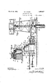
- Figure 1 is a side elevation ofmy improved oil lifting apparatus with the main suction and pressure pipes in section, parts of the oil receiving tank being also shown brokenaway and in section.
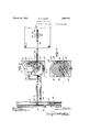
- Figure 2 is-a fragmentarytop plan view of the noveloil lilting apparatus with theoil receiving pipe'in section.
- Figure 3 is a vertical section through; the novel regulator or control valve taken 'onthe ofthe arrows.
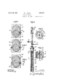
- ' Figure t isa horizontal section taken on the line H of Figure 1 lookingzin the d'irection of 'thearrows illustrating; the position of the valve plug for connecting the combined suction and pressure pipe of the well Wi'ththe' suction or vacuum field pipe.
- Figure5 is a horizontal section taken on the line 55 of Figurel looking in thefidirection of the arrows, showing the position ofthe suction release ports and-wayin-the' position shown in Figure- 4.
- FIG. 6 is a horizontal section taken .on the line 6- 6 of Figure 1 looking inthe direction ofthe arrows illustrating the po'si-' 35 tionof thea-ir pressure-way in the valve plug when the'suc'tion-way is in the position shown in Figure 4.
- Figure? is a-horizontal section taken on the" line 7'7 of Figurel 1' looking in the (iirection of the arrows, illustrating'the position of the air-pressure releaseiway in'the valve plug when the valve plug is in the position shown in Figure 4 of the drawings.
- Figure 8 is-agfragmentary side elevation of 5 the portion oflthe 'ap aratus' incorporated with the-well casing, t e well casingrbeing; part1 broken away and in; section as well as the oil receiving pipe.
- Figure 9 is'an. enlarged horizontal section me xproved apparatus, which includes a vacuum or suction line pipe 15 and a pressure line pipe 16. These line pipes 15 and 16 lead to a suitable power house which is centrally located in an oil field and these pipes lead to the various wells in the field. As clearly shownin Figure 2 of the drawings the pipes 15 and 16 are provided respectively with branch pipes 17 and 18 which lead to a well 19. Suitable gates or globe valves 20 and 21 can be placed in the line pipes 15 and 16 at the desired point for controlling the suction and pressure therein and the same can also be provided with relief or pop valves 22 if found desirable. The branch pipes 17 and 18 can also be provided respectively with globe or gate valves 23and 24 so that these pipes can be entirely shut off from the line pipes if desired.
- the well 19 can be of the usual character and as shown includes the usual wellcasing 25 provided with the casing head 26 which extends exteriorly of. the well.
- a derrick or tower 27 is arranged above the casing and in accordance with this invention supports a platform 28 on which is arranged an initial oil receiving tank 29.
- an oil receiving pipe 30 which can be of relatively great'diameter and this pipe 30 extends into the oil bearing strata 31 and out through the casing head 26into the lowerend of the initial oil receiving tank 29.
- This pipe 30 can be'made up .of suitable sections connected together in any desired way.
- a combined suction and pressure pipe 32 Arranged within the oil receiving pipe 30 is a combined suction and pressure pipe 32,
- the combined pressure and suction pipe 32 also extends into the oil bearing strata 31 and is provided with an inwardly opening valve 33 at its lower end.
- This pipe can also be made in suitable lengths or sections properly connected together and if desired means can be employed for securing thespacing of the pipe 32 from the pipe 30.
- Intermediate the length of the pipe 32 and preferably adjacent to the lower end thereof I provide coupling 34 which supports one or more. outwardly opening or. pop valves 35, the purpose of which; will be later described. Beneath the pop valves 35 the pipes 32 and 30 are connected together toas shown, includes a disc 36 which is held in friction tight engagement with the said pipe by any desired means.
- the pipe 32 Above the casing head 26, the pipe 32 is provided with an elbow joint 37, which extends out through the pipe 30 and this oint 37 has connected thereto a pipe 38 which leads to a manifold 39 having connected thereto suction and pressure pipes 40 and 41 respectively.
- a water pipe 42 leading from any suitable source of water supply is connected to the pipe 30 above the casing head and this pipe is provided with any preferred character of control valve 43.
- the pipe 30 can be filled with water abovethedise 36 to any desired height and it is preferred that the water be extended to the tank 29 or just short of thebottom thereof.
- the pipe 30 directly below the tank can be provided with a suitable cut-ofi' valve 44'so that the tank 29 can be cut off. from the well when desired.
- a suitable outlet spigot 45 can be connected to the pipe 30 above the pipe 42, so as to permit the draining of the water or oil as thecase may be from the pipe 30 above the pipe 42.
- a gravity oil outlet pipe 45? is led from the tank 29 to any suitable source of oil storage tank and this pipe extends slightly above the bottom of the tank 29 and can be provided with a head 46.
- a valve 47 is incorporated in the length of the pipe 45 directly below the tank 29, so
- a novel regulator or valve mechanism 50 for. controlling the suction in the pipe 32 and the supply of air under pressure to' the pipe 32, and this regulator or valve mechanism comprises a lower casing 51 having a tapered seat 52 for the reception of a rotatable valve plug 53.
- This rotatable valve plug 53 can be provided at its upper and lower ends with stub shafts 54 and55.
- the lower stub shaft 55 is journaled in a suitable bearing opening in the casing or block51 while the upper stub shaft 54 extends through a suitable bearing opening in a cap'plate 56 for the casing or block 51.
- the lower end of the block is provided with a flange 57 which can be bolted or otherwise secured as at 58 to a suitable supporting concrete base or the like 59.
- a gear casing 60 Secured to the cap plate 56 is a gear casing 60, which rotatably supports a drive shaft 61 to which is keyed or otherwise secured a relatively large drive gear 62. Meshing with the relatively large-drive gear'62 is a small gear or'pinion 63 which is in turn keyed or otherwise secured to the stub shaft 54 whereby upon turning of the shaft '61 the valve plug 53 will be rotated therewith.
- This shaft 61 forms a part of the drive mechanism or motor and a propeller wheel or rotor 64 is keyed or otherwise secured to the drive shaft 61 and arranged within a stator casing 65 carried by the gear casing 63.
- stator or casing 65 The opposite side of the stator or casing 65 is provided respectively with an inlet pipe 66 for fluid underpressure and an outlet exhaust pipe 67. It can be seen that when fluid under pressure is admitted to the stator casing, the same will impinge against the blades of the rotor'64 and consequently bring about the rotation thereof and the valve plug 53.
- the rotatable valve plug 53 is provided with independent diametrically extending ways 70, 71, 72 and 73. These ways extend at different angles relative to one another so that one way will be constantly in advance of the other. Each of the ways can be provided at their terminals with arcuately oppositely extending extensions 74, for a purpose which will also be later described. It is to be noted at this time that the way 70 constitutes the suction way, the Way 71 the suction relief way, the way 72 the pressure way, and the way 73 the pressure relief way.
- the casing or block 51 is provided with a pair of oppositely disposed ports 75, 76, 77
- manifold pipe 39 is connected with one way of the pair of ways and 77 by the pipes 40 and 41 while one port of the pair of ports 76 is connected with the pipe 40 by means of a branch pipe 79. The.
- branch pipe 17, leading from the suction or vacuum pipe 15 communicates with the other port of the pair of ports 75.
- the other ports 76 constitutes an escape opening.
- the branch pipe 18 of the line pressure pipe 16 communicates with the other port of the pair of ports 77 and one port of the pair of ports 78 is left open and constitutes an escape port.
- the other port of the pair of ports 78 communicates with the pipe 38 through the medium of a connecting pipe 80 which may have a control valve 81 therein.
- the turbine In operation of the improved device the turbine is set in motion by permitting fluid under pressure to flowthrough the pipe 66,
- the turbine will rotate the valve plug 53 and the way 70 will communicate with the pair of ports 75 allowing a suction to be caused in the pipe 32- arranged in the well.
- This suction will lift up the inwardly openingvalve-33 and cause the suction of oil into the pipe to a predetermined level at which time the way 70 will moveout of registrationwith its port 75 cutting off further suction in the pipe 32..
- the weight of the oil column will close the valve 33.
- the suction is cut oifthe way 71 will come into registration with the ports 76 allowing communication to: be had between the pipe 38 and the outlet or exhaust port which will relieve the vacuum Withinthe pipe 38 and the pipe 32.
- the way 71 Upon continued rotation of the valve plug the way 71 will ride past its ports 76 and the way.
- water column serves as means for permitting thefioating of the oil through the water to lift the same into the temporary storage tank, thereby decreasing the back pressure on the pop valves 35 upon the opening of the same, this water column can be eliminated if desired, and the oil allowed to flow directly into the pipe30.
- the arrangement of the power driven valve for controlling the alternate suction and pressure to and from the well forms one of the salient features of the invention, as by this means I am enabled to maintain a constant suction and pressure in the pipes 15 and 16, which is essential when the operating mechanism for maintaining the suction and pressure in the pipes 15 and-'16 is a point distant from the wells.
- the ordinary suction and pressure of a pump fails to effectively operate unless the pump is proper.
Landscapes
- Engineering & Computer Science (AREA)
- Mechanical Engineering (AREA)
- General Engineering & Computer Science (AREA)
- Jet Pumps And Other Pumps (AREA)
Description
March 29, 1932. w. D. GILES AIR-WATER OIL LIFT Filed Sept. 29, 1928 5 Sheets-Sheet I N VEN TOR. WALTER D. 67155 WIT/V5555 A TTORNEYS.
March 29, 1932. w. D. GlLES AIR-WATER OIL LIFT Filed Sept. 29, 1928 3 Sheets-Sheet 2 IN VEN TOR.
ML TE"? 0. 671.55
BY M A TTORNEYS.
VIM/E6555 March 29,- 1932. w, D, (5|LES 1,851,827
AIR-WATER OIL LIFT Filed Sept. 29, 1928 3 Sheets-Sheet 3 IN V EN TOR. M41. 75/? 0. 0/455 A mmm= Patented Mar. 29, 1932 RATE Q I- GE (WALTER, n. arms, or 1 summons; LOUISIANA AIR-W TER; 0.11. i-
npplication filed September 29,1928. SerialNoi 309,306.
"This invention relates to wells and more particularly to means for lifting oil from-deep or shallow oil wells. 7
fOne ofqthe primaryobjects of-my-inventionisfthe provision of'novelmeans for operating a plurality of oilwells simultaneously from a central "operating station, sald means including the useof a vacuum-pres other apressure line with a novel-regulator for controlling the suction-of the vacuum and pressure in said well.
Another object of the inventionis the provision of means for lifting o'iljfrom an oil well embodying arelative large delivery pipe extending into the well-casing-and leading into an 'ove'rhead temporary storage tank with a combined pressure. and suction pipe leading into saiddelivery pipe and the source of oil supply, said combinedpressure and suction pipe-having an inwardly opening intake valve and; anoutwardlyiopening outlet valve with means for controllin first, a suction'in the, pipefor drawing oil into the same; and, second, pressure enforcing the valve plug when the suction way is inthe oil from said pipe. I I
A further object of the inventionis the provision of .a novel control valve constantly operatedg for. intermittently controlling first the suction and then the pressure in the pipe with, means alternately relieving the suction and the pressure in thepipe. V v
. A further obj ectof the inventionis the provision. of water. interposed between. the. .delivery pipe and the combinedsuctionand ins take pipe, whereby when the oil is forced out of the combined suctionv and pressure pipe the same ;.will float-iupwardly in the water into the receiving tank therefore. Y
'A' still further object of the invention is toprovide an improvedoil lifting device of the above character, :which will be durable and e'fiicient in use, one that will easy and simple to-manu'facture, and one which can be,
'NVith these andother-objects in view, the invention consists in the novel construction, arrangement and formation of partsas will be hereinafter more specifically described, claimed andillustrated in the accompanying drawings, in which drawings:
Figure 1 is a side elevation ofmy improved oil lifting apparatus with the main suction and pressure pipes in section, parts of the oil receiving tank being also shown brokenaway and in section.
Figure 2 is-a fragmentarytop plan view of the noveloil lilting apparatus with theoil receiving pipe'in section.
Figure 3 is a vertical section through; the novel regulator or control valve taken 'onthe ofthe arrows.
'Figure t isa horizontal section taken on the line H of Figure 1 lookingzin the d'irection of 'thearrows illustrating; the position of the valve plug for connecting the combined suction and pressure pipe of the well Wi'ththe' suction or vacuum field pipe. f
Figure5 is a horizontal section taken on the line 55 of Figurel looking in thefidirection of the arrows, showing the position ofthe suction release ports and-wayin-the' position shown in Figure- 4.
-Figure 6 is a horizontal section taken .on the line 6- 6 of Figure 1 looking inthe direction ofthe arrows illustrating the po'si-' 35 tionof thea-ir pressure-way in the valve plug when the'suc'tion-way is in the position shown inFigure 4. i
Figure? is a-horizontal section taken on the" line 7'7 of Figurel 1' looking in the (iirection of the arrows, illustrating'the position of the air-pressure releaseiway in'the valve plug when the valve plug is in the position shown inFigure 4 of the drawings.
Figure 8 is-agfragmentary side elevation of 5 the portion oflthe 'ap aratus' incorporated with the-well casing, t e well casingrbeing; part1 broken away and in; section as well as the oil receiving pipe.
"Figure 9 is'an. enlarged horizontal section me xproved apparatus, which includes a vacuum or suction line pipe 15 and a pressure line pipe 16. These line pipes 15 and 16 lead to a suitable power house which is centrally located in an oil field and these pipes lead to the various wells in the field. As clearly shownin Figure 2 of the drawings the pipes 15 and 16 are provided respectively with branch pipes 17 and 18 which lead to a well 19. Suitable gates or globe valves 20 and 21 can be placed in the line pipes 15 and 16 at the desired point for controlling the suction and pressure therein and the same can also be provided with relief or pop valves 22 if found desirable. The branch pipes 17 and 18 can also be provided respectively with globe or gate valves 23and 24 so that these pipes can be entirely shut off from the line pipes if desired.
The well 19 can be of the usual character and as shown includes the usual wellcasing 25 provided with the casing head 26 which extends exteriorly of. the well. A derrick or tower 27 is arranged above the casing and in accordance with this invention supports a platform 28 on which is arranged an initial oil receiving tank 29.
Iplace in the well casing 25, an oil receiving pipe 30 which can be of relatively great'diameter and this pipe 30 extends into the oil bearing strata 31 and out through the casing head 26into the lowerend of the initial oil receiving tank 29. r
This pipe 30 can be'made up .of suitable sections connected together in any desired way. I
Arranged within the oil receiving pipe 30 is a combined suction and pressure pipe 32,
' which pipe is of considerably less diameter than the oil receiving pipe. The combined pressure and suction pipe 32 also extends into the oil bearing strata 31 and is provided with an inwardly opening valve 33 at its lower end. This pipe can also be made in suitable lengths or sections properly connected together and if desired means can be employed for securing thespacing of the pipe 32 from the pipe 30. Intermediate the length of the pipe 32 and preferably adjacent to the lower end thereof I provide coupling 34 which supports one or more. outwardly opening or. pop valves 35, the purpose of which; will be later described. Beneath the pop valves 35 the pipes 32 and 30 are connected together toas shown, includes a disc 36 which is held in friction tight engagement with the said pipe by any desired means. Above the casing head 26, the pipe 32 is provided with an elbow joint 37, which extends out through the pipe 30 and this oint 37 has connected thereto a pipe 38 which leads to a manifold 39 having connected thereto suction and pressure pipes 40 and 41 respectively.
Again referring to the well, a water pipe 42 leading from any suitable source of water supply is connected to the pipe 30 above the casing head and this pipe is provided with any preferred character of control valve 43.
y means of the pipe 42, the pipe 30 can be filled with water abovethedise 36 to any desired height and it is preferred that the water be extended to the tank 29 or just short of thebottom thereof. The pipe 30 directly below the tank can be provided with a suitable cut-ofi' valve 44'so that the tank 29 can be cut off. from the well when desired. A suitable outlet spigot 45 can be connected to the pipe 30 above the pipe 42, so as to permit the draining of the water or oil as thecase may be from the pipe 30 above the pipe 42.
A gravity oil outlet pipe 45? is led from the tank 29 to any suitable source of oil storage tank and this pipe extends slightly above the bottom of the tank 29 and can be provided with a head 46. j
A valve 47 is incorporated in the length of the pipe 45 directly below the tank 29, so
that the flow of oil can be shut off through the pipe 45 when so desired. 7 I provide a novel regulator or valve mechanism 50 for. controlling the suction in the pipe 32 and the supply of air under pressure to' the pipe 32, and this regulator or valve mechanism comprises a lower casing 51 having a tapered seat 52 for the reception of a rotatable valve plug 53. This rotatable valve plug 53 .can be provided at its upper and lower ends with stub shafts 54 and55. The lower stub shaft 55 is journaled in a suitable bearing opening in the casing or block51 while the upper stub shaft 54 extends through a suitable bearing opening in a cap'plate 56 for the casing or block 51. As shown the lower end of the block is provided with a flange 57 which can be bolted or otherwise secured as at 58 to a suitable supporting concrete base or the like 59.
Secured to the cap plate 56 is a gear casing 60, which rotatably supports a drive shaft 61 to which is keyed or otherwise secured a relatively large drive gear 62. Meshing with the relatively large-drive gear'62 is a small gear or'pinion 63 which is in turn keyed or otherwise secured to the stub shaft 54 whereby upon turning of the shaft '61 the valve plug 53 will be rotated therewith. This shaft 61 forms a part of the drive mechanism or motor and a propeller wheel or rotor 64 is keyed or otherwise secured to the drive shaft 61 and arranged within a stator casing 65 carried by the gear casing 63. The opposite side of the stator or casing 65 is provided respectively with an inlet pipe 66 for fluid underpressure and an outlet exhaust pipe 67. It can be seen that when fluid under pressure is admitted to the stator casing, the same will impinge against the blades of the rotor'64 and consequently bring about the rotation thereof and the valve plug 53.
The rotatable valve plug 53 is provided with independent diametrically extending ways 70, 71, 72 and 73. These ways extend at different angles relative to one another so that one way will be constantly in advance of the other. Each of the ways can be provided at their terminals with arcuately oppositely extending extensions 74, for a purpose which will also be later described. It is to be noted at this time that the way 70 constitutes the suction way, the Way 71 the suction relief way, the way 72 the pressure way, and the way 73 the pressure relief way.
The casing or block 51 is provided with a pair of oppositely disposed ports 75, 76, 77
and 78 and when the way 71 is in one position the same will register the pair of ports 75 as shown in Figure 4 of the drawings, and after the way 70 has passed the ports 75, the way 71 will register with the pair of ways 76, and after the way 71 has passed its ports 76 the way 72 will register with the ports 77 and when the way 72 passes its ports 77, the way 73 will register with the ports 78, after which the upper way will again register with its pair of ports 75.
As shown the manifold pipe 39 is connected with one way of the pair of ways and 77 by the pipes 40 and 41 while one port of the pair of ports 76 is connected with the pipe 40 by means of a branch pipe 79. The.
In operation of the improved device the turbine is set in motion by permitting fluid under pressure to flowthrough the pipe 66,
which pipe, as shown, communicates with the branch pipe 18.
As stated, the turbine will rotate the valve plug 53 and the way 70 will communicate with the pair of ports 75 allowing a suction to be caused in the pipe 32- arranged in the well. This suction will lift up the inwardly openingvalve-33 and cause the suction of oil into the pipe to a predetermined level at which time the way 70 will moveout of registrationwith its port 75 cutting off further suction in the pipe 32.. The weight of the oil column will close the valve 33. As soon as the. suction is cut oifthe way 71 will come into registration with the ports 76 allowing communication to: be had between the pipe 38 and the outlet or exhaust port which will relieve the vacuum Withinthe pipe 38 and the pipe 32. Upon continued rotation of the valve plug the way 71 will ride past its ports 76 and the way. 72 will come into registration with its pair. of ports 77. This will allow communication to be had between the pipe 18, pipe 41, manifold 39, pipe 38, and pipe 32. Air under pressure is thus admitted to the pipe'32 and this air willv force the oil out of the pipe 32 through the outwardly opening pop valves 35 into the pipe 30. This pipe being filled. with water will allow the oil to float to the top and then into the tank 29. After the way 72 has moved past its ports 7 7 the way 73 will register with its ports 78 which will connectthe pipe 80 and consequently the . pipes 38 and 32 with the exhaust port 78 ofthis pair of ports-and thus relieve the pressure within the pipe 32. This cycle of operation is continued and it can be seen that a continued suction and pressure is alternately -maintainedjwithinthe pipe 32. VVhen the oil reaches the head 46 in the tank 29 the oil. will flow through the pipe 45 into a suitablestoragetank.
While, as heretobefore stated, I prefer to employ a column of water in pipe 30, as .the
water column, serves as means for permitting thefioating of the oil through the water to lift the same into the temporary storage tank, thereby decreasing the back pressure on the pop valves 35 upon the opening of the same, this water column can be eliminated if desired, and the oil allowed to flow directly into the pipe30.
From the foregoing description, it can be seen that I have provided a novel device for pumping oil from wells, in which asingle centrally located power station can be used for a plurality of wells. The arrangement of the power driven valve for controlling the alternate suction and pressure to and from the well forms one of the salient features of the invention, as by this means I am enabled to maintain a constant suction and pressure in the pipes 15 and 16, which is essential when the operating mechanism for maintaining the suction and pressure in the pipes 15 and-'16 is a point distant from the wells. The ordinary suction and pressure of a pump fails to effectively operate unless the pump is proper.
Changes in details may be made without departing from the spirit or the scope of this invention, but: 4
What I claim as new is:
- 1. In an oil well, the combination with a well casing, an oil well pipe extending into the casing, an initial oil receiving tank having communication with the oil pipe, a combined suction and pressure pipe arranged within the oil pipe and in spaced relation thereto, an inwardly opening inlet valve for said combined suction and pressure pipe, an outwardly opening outlet valve for said combined suction and pressure pipe, means for sealing the oil pipe and the combinedpressure and suction pipe together between said valves, means for maintaining a column water in said oil pipe, and means for alternately causing a suction and a pressure in said combined suction and pressure pipe.
2. In an oil well, the combination with a well casing, an oil pipe extending into said casing, a combined pressure and suction pipe arranged within the oil pipe, an initial oil receiving tank having communication with the oil'pipe, the combined pressure and suction pipe having spaced inlet and outlet Valves, means sealing the combined pressure and suction pipe with the oil pipe intermedi-' ate said valves, means introducing a water column in said oil pipe, an oil outlet pipe communicating with the initial oil receiving tank, a pressure line pipe, a suction line pipe, and means for alternately connecting first the suction pipe with the combined suction and pressure pipe and then the pressure line pipe with said combined suction and pressure pipe. 7
In testimony whereof I afiix my signature.
WALTER D. GILES.
Priority Applications (1)
| Application Number | Priority Date | Filing Date | Title |
|---|---|---|---|
| US309306A US1851827A (en) | 1928-09-29 | 1928-09-29 | Air-water oil lift |
Applications Claiming Priority (1)
| Application Number | Priority Date | Filing Date | Title |
|---|---|---|---|
| US309306A US1851827A (en) | 1928-09-29 | 1928-09-29 | Air-water oil lift |
Publications (1)
| Publication Number | Publication Date |
|---|---|
| US1851827A true US1851827A (en) | 1932-03-29 |
Family
ID=23197639
Family Applications (1)
| Application Number | Title | Priority Date | Filing Date |
|---|---|---|---|
| US309306A Expired - Lifetime US1851827A (en) | 1928-09-29 | 1928-09-29 | Air-water oil lift |
Country Status (1)
| Country | Link |
|---|---|
| US (1) | US1851827A (en) |
-
1928
- 1928-09-29 US US309306A patent/US1851827A/en not_active Expired - Lifetime
Similar Documents
| Publication | Publication Date | Title |
|---|---|---|
| US7789158B2 (en) | Flow control system having a downhole check valve selectively operable from a surface of a well | |
| US2214677A (en) | Portable adjustable pump | |
| US2180173A (en) | Float valve for hydraulic pumping systems | |
| US2113213A (en) | Fluid operated pump | |
| US1894393A (en) | Turbine pump | |
| US2371704A (en) | Double-action pump | |
| US1851827A (en) | Air-water oil lift | |
| CN207260998U (en) | The small coiled tubing bubble row of coal bed gas, gaslift water pumping gas production system | |
| CN205477566U (en) | Crude oil collection system | |
| US2020956A (en) | Pumping unit | |
| US2202970A (en) | Oil well pump | |
| US2187969A (en) | Drilling system | |
| US2517841A (en) | Unloading valve for oil well pumps and the like | |
| US1291407A (en) | Rotary deep-well pump. | |
| US1927055A (en) | Method of and apparatus for pumping wells with pressure fluid | |
| RU2011888C1 (en) | Well pump station | |
| USRE18527E (en) | Well pumping apparatus | |
| US1970917A (en) | Pump attachment for pneumatic swabs | |
| CN204344427U (en) | A kind of wind-force deep-well pump | |
| US1778501A (en) | Well-drilling system | |
| US1735025A (en) | Pumping apparatus | |
| US2362249A (en) | Well equipment | |
| US1323146A (en) | Watee-elevator | |
| US1077088A (en) | Apparatus for hoisting liquids from wells. | |
| US1792723A (en) | Forced-feed fluid-transporting mechanism |