US1851815A - Laundry ironing and like machine - Google Patents
Laundry ironing and like machine Download PDFInfo
- Publication number
- US1851815A US1851815A US327940A US32794028A US1851815A US 1851815 A US1851815 A US 1851815A US 327940 A US327940 A US 327940A US 32794028 A US32794028 A US 32794028A US 1851815 A US1851815 A US 1851815A
- Authority
- US
- United States
- Prior art keywords
- pressure
- rollers
- machine
- levers
- pistons
- Prior art date
- Legal status (The legal status is an assumption and is not a legal conclusion. Google has not performed a legal analysis and makes no representation as to the accuracy of the status listed.)
- Expired - Lifetime
Links
Images

Classifications
-
- D—TEXTILES; PAPER
- D06—TREATMENT OF TEXTILES OR THE LIKE; LAUNDERING; FLEXIBLE MATERIALS NOT OTHERWISE PROVIDED FOR
- D06F—LAUNDERING, DRYING, IRONING, PRESSING OR FOLDING TEXTILE ARTICLES
- D06F65/00—Ironing machines with rollers rotating against curved surfaces
- D06F65/10—Ironing machines with rollers rotating against curved surfaces with two or more rollers co-operating with two or more curved surfaces
Definitions
- rollers in association with a steam-heated bed.
- the object of the present invention is to avoid these diflicultiesand to provide adjustment and like means adapted automatically to function according to predetermined con-,
- the pressure afforded between rollers and their beds and/or the tension of apron bands and the like is maintained and adjusted by the aid of fluid pressure adapted to afford and automatically maintain a predetermined pressure or tension for the parts.
- the invention also comprises mounting or associating each padded or like roller of the ironing machine, upon or with a device (including, for example, a piston and cylinder). subjected to a fluid pressure so that the rollers will exert a pressure corresponding with that at which the fluid pressure is predetermined for individual rollers.
- the device may also be adapted to afford a displacement of the rollers individually or collectively under the control action of the fluid pressure means, such that the rollers may be moved in and out of their operative position.
- fluid pressure means may be adapted to apply predetermined tension to aprons, bands, ribbons, or like conveyor or feed device.
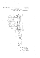
- Figure 1 is a diagrammatic'fragmentary 'vention.
- Figure 2 is a plan view of the arrangement according to Figure 1,
- FIG. 8 is asectional diagram showing an arrangement of hydraulic cylinders applied to each side of the rollers according to the in- In carrying the invention into eifect according to one convenient mode, the trunnions 1 on each side of the pressure rollers 2 (operating in conjunction with a steam heated bed 3) are mounted in bearing blocks 4 which are adapted to slide in vertical guides of the machine (not shown).
- the bearing blocks are carried by connecting rods 4d which may be suitably guided and are adjustably positioned on levers 5 for which purpose the levers may be provided with a series of adjustment holes 6 for the reception of the pins] securing the rods 4a.
- Each lever 5 is pivotally mounted at 8 on a bracket. 9 ex tending from a hydraulic cylinder 10.
- the other ends of the levers 5 are pivotally connected to piston rods 11 working in the cylinders 10.
- the piston rods 11 may have any suitable form of sealed piston 12 and the arrangementis such that on the stroke of the piston, taking into consideration the lever adjustment, the rollers 2 may beraised from their beds to any suitable extent for inspection or repair purposes and lowered again.
- Each cylinder 10 is double-acting and is provided with ports adapted to function alternately for inlet and exhaust and with which "pipe connections 13, 13a communicate, re-
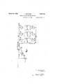
- the pipes 14 are arranged to carry water of the cylinders for developing the pressure ada ted to cause the rollers 2 to maintain a pre etermined pressure with respect to'the bed 3 while the pipe 15 is adapted to supply of the machine are in parallel and that the pipe line 14 of the machine has a return pipe line connection 18.
- a suitable adjustable relief or automatic control valve 20 adapted to operate at a predetermined pressure so that a chosen pressure for the rollers may be developed and maintained while excess water escapes through the valve 20 to return byway of the pipe 18.
- a centrifugal or other pump 21 which draws from a suitable supply tank 22 is provided to discharge along a pipe line 23 to both valves 16, '17 by an intermediate connection 24.
- a predetermined head of water is maintained in the tank 22 by aid of the float supp y a
- the valve 16 is provided with a pipe connection 26, with which the pipe 18 communicates at 18a back to the tank 22.
- the valve 17 has a pipe connection 27 to waste or back to the tank 22; p
- the pump 21 delivers through the pipe line. 23, valve 16, pipe lines 14 so that hydraulic pressur acts on the upper surface of the pistons 12 on each side of the machine to draw the rollers equally on each side thereof down upon their beds. Circulation takes place through the pipes 18 and 26 back to the tank 22 and the relief or control valve 20 automatically maintains the pressure on the pistons 12 at a predetermined value according to the setting of the valve.
- valve 16 When it is desired to raise the rollers 2 from their beds 3 the valve 16 is operated to communicate with the pipes 14a and 26 and the valve 17 is turned to communicate with the connections 24 and 15a. In this position pressure is applied to the lower sides of the piston 12 and the pistons are displaced the full length of their stroke, raising the rollers from their bedssimultaneously.
- each pressure roller 2 is acted upon-on each side by an equal and predetermined pressure which may be varied according to requirements by adjustment of the control valve 20.
- valves 16, 17 may be operated simultaneously for the change over from the position in which the predetermined pressure of the rollers upon their beds is maintained to the position in which the rollers are elevated.
- connections between the pistons and the bearings and means included in said connections for varying the pressure on the bearing inde endently of t e fluid pressure in the cylm er.
- a plurality'of bearings supporting members adapted to rotate therein, a plurality of hydraulic cylinders, one for eachbearing, pistons in said cylinders, levers connected to said pistons, fulcrums for said levers, coupling rods connecting the levers to the respective bearings and means for adjusting the relative lengths of the arms of the lever whereby the pressure on the respective bearing may be varied independently of the fluid pressure in the c linder.
- a p urality of bearings supporting members adapted to rotate therein, a plurality of hydraulic cylinders, one for each bearing, a pressure fluid conduit common to said cylinders, a relief valve in said conduit, pistons in said 0 linders, levers connected to said pistons, ulcrums for levers, coupling rods connecting the levers to the respective bearings, the connections to the levers bein adjustable to vary the relative lengths o the arms of the levers whereby the pressure on the respective bearing may be varied independently of the fluid pressure in the cylinder.
- a pair of hydraulic cylinders one for each bearing, a pressure fluid conduit common to said cylinders, a relief valve in said conduit, pistons in said cylinder, levers connected to said pistons, fulcrums for the levers, coupling rods connecting the bearings to the respective levers, and means for adjusting the relative lengths of the arms of each lever whereby the pressure on the bearings may be varied independently of the fluid pressure in the respective cylinders.
Landscapes
- Engineering & Computer Science (AREA)
- Textile Engineering (AREA)
- Treatment Of Fiber Materials (AREA)
Description
March 29, 1932. F. DEWHURST ,8
LAUNDRY IRO NING AND LIKE MACHINE Filed Dec. 22, 1928 3 Sheets-Sheet 1 Fig.1
7 w/7am?" March 29, 1932. F DEWHURST 1,851,815
LAUNDRY IRONING AND LIKE MACHINE Filed Dec. 22, 1928 3 Sheets-Sheet 2 March 29, 1932. DEWHURST 1,851,815
LAUNDRY IlONING AND LIKE MACHINE Filed Dec. 22, 1928 5 Sheets-Sheet 3 Patented Mar. 29 1932' 1 UN TED STATES PATENT OFFICE FRANK DEWHUBSI', OI WISTWOOD WORKS, PETERBOROUGH, ENGLAND, ASSIGNOB TO BAKER PERKINS, LIMITED, 01' PETEBBOROUGH, ENGLAND V LAUNDRY IRONING AND LIKE K ACHINE Application filed December 22, 1928, Serial No. 827,940, and in Great Britain January 25, 1928.
' rollers in association with a steam-heated bed.
In such machines provision is made for mechanically altering the pressure of rollers and the tension of aprons, conveyors or bands or like feeding means. Hitherto these adjust ment means have involved somewhat numerous manipulations and have been open to the objection that they oiier opportunity for 1njudicious or haphazard alteration by the operatives or attendants, which has given use to breakages and other defects.
The object of the present invention is to avoid these diflicultiesand to provide adjustment and like means adapted automatically to function according to predetermined con-,
ditions calculated to afford the most efficient operation of the machine.
According to the invention the pressure afforded between rollers and their beds and/or the tension of apron bands and the like is maintained and adjusted by the aid of fluid pressure adapted to afford and automatically maintain a predetermined pressure or tension for the parts.
4 The invention also comprises mounting or associating each padded or like roller of the ironing machine, upon or with a device (including, for example, a piston and cylinder). subjected to a fluid pressure so that the rollers will exert a pressure corresponding with that at which the fluid pressure is predetermined for individual rollers. The device may also be adapted to afford a displacement of the rollers individually or collectively under the control action of the fluid pressure means, such that the rollers may be moved in and out of their operative position. Similarly, fluid pressure means may be adapted to apply predetermined tension to aprons, bands, ribbons, or like conveyor or feed device.
In the accompanying drawings Figure 1 is a diagrammatic'fragmentary 'vention.
side elevation of an ironing machine and ill'ustrating the application of the invention to the pressure rollersin association with their bed.
Figure 2 is a plan view of the arrangement according to Figure 1,
Figure 8 is asectional diagram showing an arrangement of hydraulic cylinders applied to each side of the rollers according to the in- In carrying the invention into eifect according to one convenient mode, the trunnions 1 on each side of the pressure rollers 2 (operating in conjunction with a steam heated bed 3) are mounted in bearing blocks 4 which are adapted to slide in vertical guides of the machine (not shown). The bearing blocks are carried by connecting rods 4d which may be suitably guided and are adjustably positioned on levers 5 for which purpose the levers may be provided with a series of adjustment holes 6 for the reception of the pins] securing the rods 4a. Each lever 5 is pivotally mounted at 8 on a bracket. 9 ex tending from a hydraulic cylinder 10. The other ends of the levers 5 are pivotally connected to piston rods 11 working in the cylinders 10. The piston rods 11 may have any suitable form of sealed piston 12 and the arrangementis such that on the stroke of the piston, taking into consideration the lever adjustment, the rollers 2 may beraised from their beds to any suitable extent for inspection or repair purposes and lowered again. Each cylinder 10 is double-acting and is provided with ports adapted to function alternately for inlet and exhaust and with which " pipe connections 13, 13a communicate, re-
spectively, with common pipes or headers 14, 15 on one side of the machine, and similar pipes on the other side of the machine.
The pipes 14 are arranged to carry water of the cylinders for developing the pressure ada ted to cause the rollers 2 to maintain a pre etermined pressure with respect to'the bed 3 while the pipe 15 is adapted to supply of the machine are in parallel and that the pipe line 14 of the machine has a return pipe line connection 18. In the pipe line 18 is located a suitable adjustable relief or automatic control valve 20 adapted to operate at a predetermined pressure so that a chosen pressure for the rollers may be developed and maintained while excess water escapes through the valve 20 to return byway of the pipe 18.
A centrifugal or other pump 21 which draws from a suitable supply tank 22 is provided to discharge along a pipe line 23 to both valves 16, '17 by an intermediate connection 24. A predetermined head of water is maintained in the tank 22 by aid of the float supp y a The valve 16 is provided with a pipe connection 26, with which the pipe 18 communicates at 18a back to the tank 22. The valve 17 has a pipe connection 27 to waste or back to the tank 22; p
In normal operation for maintaining a predetermined pressure of the rollers upon their beds, the pump 21 delivers through the pipe line. 23, valve 16, pipe lines 14 so that hydraulic pressur acts on the upper surface of the pistons 12 on each side of the machine to draw the rollers equally on each side thereof down upon their beds. Circulation takes place through the pipes 18 and 26 back to the tank 22 and the relief or control valve 20 automatically maintains the pressure on the pistons 12 at a predetermined value according to the setting of the valve.
When it is desired to raise the rollers 2 from their beds 3 the valve 16 is operated to communicate with the pipes 14a and 26 and the valve 17 is turned to communicate with the connections 24 and 15a. In this position pressure is applied to the lower sides of the piston 12 and the pistons are displaced the full length of their stroke, raising the rollers from their bedssimultaneously.
. It will be observed that according to the above arrangements each pressure roller 2 is acted upon-on each side by an equal and predetermined pressure which may be varied according to requirements by adjustment of the control valve 20.
The valves 16, 17 may be operated simultaneously for the change over from the position in which the predetermined pressure of the rollers upon their beds is maintained to the position in which the rollers are elevated. Having now described my invention, what I claim as new and desire to secure by Letters Patent is 1. In combination a plurality of bearings supporting members adapted to rotate in said bearings, a lurality of hydraulic cylinders, one for each caring, pistons in said cylinders,
connections between the pistons and the bearings, and means included in said connections for varying the pressure on the bearing inde endently of t e fluid pressure in the cylm er.
2. In combination a plurality of bearings supporting members adapted to rotate therein, a lurality of hydraulic cylinders, one for each caring, a pressure fluid conduit common to said cylinder a relief valve in said conduit, pistons in said cylinders, connec tions between the pistons and the associated bearings, means included in said connections for varying the pressure on the bearing independently of the fluid pressure in the cylin- 3. In combination, a plurality'of bearings supporting members adapted to rotate therein, a plurality of hydraulic cylinders, one for eachbearing, pistons in said cylinders, levers connected to said pistons, fulcrums for said levers, coupling rods connecting the levers to the respective bearings and means for adjusting the relative lengths of the arms of the lever whereby the pressure on the respective bearing may be varied independently of the fluid pressure in the c linder.
4. In combination, a p urality of bearings supporting members adapted to rotate therein, a plurality of hydraulic cylinders, one for each bearing, a pressure fluid conduit common to said cylinders, a relief valve in said conduit, pistons in said 0 linders, levers connected to said pistons, ulcrums for levers, coupling rods connecting the levers to the respective bearings, the connections to the levers bein adjustable to vary the relative lengths o the arms of the levers whereby the pressure on the respective bearing may be varied independently of the fluid pressure in the cylinder.
5. In combination, a plurality of bearings supporting members adapted to rotate therein, a plurality of hydraulic cylinders, one for each bearing, a' pressure fluid conduit common tosaid cylinders, .a relief valve in-said conduit, pistons in said cylinders, levers connected to said istons and fulcrumed in brackets on said cy inders, coupling rods connecting the bearings to the levers at a point between the fulcrum and the connection to the piston, and means for adjusting the distance of the point of connection of the coupling rod to the levers and said fulcrum, whereby the pressure on the respective hearing may be varied independently of the fluid pressure in the cylinde 6. In combination a pair of bearin supporting a member adapted to rotate t erein,
a pair of hydraulic cylinders, one for each bearing, a pressure fluid conduit common to said cylinders, a relief valve in said conduit, pistons in said cylinder, levers connected to said pistons, fulcrums for the levers, coupling rods connecting the bearings to the respective levers, and means for adjusting the relative lengths of the arms of each lever whereby the pressure on the bearings may be varied independently of the fluid pressure in the respective cylinders.
In testimony whereof I have signed my name to this specification.
FRANK DEWHURST.
Applications Claiming Priority (1)
| Application Number | Priority Date | Filing Date | Title |
|---|---|---|---|
| GB1851815X | 1928-01-25 |
Publications (1)
| Publication Number | Publication Date |
|---|---|
| US1851815A true US1851815A (en) | 1932-03-29 |
Family
ID=10891982
Family Applications (1)
| Application Number | Title | Priority Date | Filing Date |
|---|---|---|---|
| US327940A Expired - Lifetime US1851815A (en) | 1928-01-25 | 1928-12-22 | Laundry ironing and like machine |
Country Status (1)
| Country | Link |
|---|---|
| US (1) | US1851815A (en) |
-
1928
- 1928-12-22 US US327940A patent/US1851815A/en not_active Expired - Lifetime
Similar Documents
| Publication | Publication Date | Title |
|---|---|---|
| US2419695A (en) | Machine for stencilling fabric with suction | |
| US1851815A (en) | Laundry ironing and like machine | |
| US2126577A (en) | Garment pressing machine | |
| US2652644A (en) | Flatwork ironing machine | |
| US2011980A (en) | Tandem cylinder glass plunger actuator | |
| US1936027A (en) | Laundry ironing and like machine | |
| US3484966A (en) | Ironing machine | |
| US3209679A (en) | Roll bending device | |
| US2156712A (en) | Laundering apparatus | |
| US1930986A (en) | Tarn printing machine | |
| US2535732A (en) | Sealed wet end for paper machines | |
| US3361056A (en) | Device for obtaining a simultaneous movement and balancing of the pressplatens in a multi-platen hot press | |
| US2352422A (en) | Ironing machine | |
| US1679711A (en) | Paper-calendering device | |
| CN209584590U (en) | A kind of garment production cloth drying device | |
| US1846439A (en) | Metal working press | |
| US2010097A (en) | Pressing apparatus | |
| US3191325A (en) | Ironing machines | |
| US1818719A (en) | Paper making machinery | |
| US1764777A (en) | Means for eliminating wet streaks in paper | |
| US1501307A (en) | Garment former | |
| US3170192A (en) | Device for corrugating sheets of fibrous cement | |
| US2656625A (en) | Garment and like presses | |
| CN116949733B (en) | An automated ironing system for knitted sweaters | |
| US1372766A (en) | Calendering-machine |