US1851813A - Shiftable door bottom - Google Patents
Shiftable door bottom Download PDFInfo
- Publication number
- US1851813A US1851813A US468157A US46815730A US1851813A US 1851813 A US1851813 A US 1851813A US 468157 A US468157 A US 468157A US 46815730 A US46815730 A US 46815730A US 1851813 A US1851813 A US 1851813A
- Authority
- US
- United States
- Prior art keywords
- door
- rod
- recess
- frame
- spring
- Prior art date
- Legal status (The legal status is an assumption and is not a legal conclusion. Google has not performed a legal analysis and makes no representation as to the accuracy of the status listed.)
- Expired - Lifetime
Links
Images
Classifications
-
- E—FIXED CONSTRUCTIONS
- E06—DOORS, WINDOWS, SHUTTERS, OR ROLLER BLINDS IN GENERAL; LADDERS
- E06B—FIXED OR MOVABLE CLOSURES FOR OPENINGS IN BUILDINGS, VEHICLES, FENCES OR LIKE ENCLOSURES IN GENERAL, e.g. DOORS, WINDOWS, BLINDS, GATES
- E06B7/00—Special arrangements or measures in connection with doors or windows
- E06B7/16—Sealing arrangements on wings or parts co-operating with the wings
- E06B7/18—Sealing arrangements on wings or parts co-operating with the wings by means of movable edgings, e.g. draught sealings additionally used for bolting, e.g. by spring force or with operating lever
- E06B7/20—Sealing arrangements on wings or parts co-operating with the wings by means of movable edgings, e.g. draught sealings additionally used for bolting, e.g. by spring force or with operating lever automatically withdrawn when the wing is opened, e.g. by means of magnetic attraction, a pin or an inclined surface, especially for sills
Definitions
- This invention relates toattachments for doors particularly inside doors.
- the primary object of the present invention is to provide va device applicable to the .3 lower edge of a door which, when the door is closed, will move downwardly into engagement with the floor beneath and thus completely close the opening existing between the lower edge of the door and the floor thereby lu preventing the passage of air from one room to another and the creation of drafts.
- Another object of the invention is to provide a device of the above described character which operates automatically through the l contact of an element forming a part thereof with the jamb of the door frame so that the operation of the device will be positive at all times.
- Still another object of the invention is to 'en provide a device of the above described character which, when lthe door is open, will be raised to a plane above the lower edge of the door so that the door may be swung over rugs or other articles upon the floor without the device coming into contact therewith and interfering with the proper operation of the door.
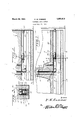
- Figure 1 is a view partially in elevation and partially in section of the device embodying the present invention showing the same applied and in raised position.
- Figure 2 is a view similar to Figure 1 showing the device in lowered position.
- Figure 3 is a sectional view taken on the line 3--3 of Figure 1.
- FIG. 3 a cross-section of the lower part of a door indicated by the numeral 1.
- thisr lower'part of the door is providedV with a 55 recess 2 which extends from one side'of the door to the lother or, in other words, from they front'to they rear edge thereof.
- This recessV 2y opens throughv the bottom edgey of, j the door as shownl so that the attachment ⁇ embodying the present invention may be extended therefrom for contact with the floor 3 beneath the door, when the door is shut.
- the attachment embodying the presentl inl vention and whichy is disposedA transversely 615k of the lower part of the door 1 in the recess 2, comprises an inverted substantially U- shaped metal frame 4 through the horizontal top Lportion of which one or more screws 5 may be passed into the adjacent portion of 7o the door body to maintain this frame in position therein.
- the frame 4 is preferably placed in the central part of the door and adjacent the Y forward end of the frame the door body has formed upwardly therein from the recess 2 a bore 6 into which may extend a coil spring 7 the ⁇ lower end of which rests upon the top of the frame 4A and overlies an ⁇ opening k8 I formed therethrough.
- Extending upwardly through the opening 8 and longitudinally through the spring 7 isapull rod 9, the upper end of whichpasses through a washer 10 upon the top of the spring 7 and receives a transverse key 11 which prevents it being 85 ,pulled through the spring as will be ⁇ readily understood upon reference to Figure 1 of the drawings.
- the lower end of this rod is flattenedand provided with an aperturem 12 for the purpose hereinafter described.
- a plate 15 which extends longitudinally of the frame as shown and which carries adjacent the rear portion of the frame a pivot stud 16 which extends laterallyinto the adjacent side ofthe framesm 4 with which it is in pivotal connection.
- the plates 15 areconnected at their top edges by a cross bar 17 which overlies the shell 13 and bears thereagainst during the operation of the attachment.
- the shell 13 carries upon its top a hook 18 which engages in the aperture 12 in the pull rod 9.
- v Adjacent their rear ends and at the top edges thereof the oscillatable plates 15 are connected by a cross bar 19.
- This bar is pivoted in the plates 15. Extending through and in threaded connection with the pivoted bar 19 is a push rod 20 which extends longitudinally and over the top of the felt carrying shell ⁇ 13 to and beyond the rear edge of the door 1, The rear end of thisrod 2O is provided with a kerf 21 in which a screwdriver may be engaged so that the rod may be rotated and adjusted longitudinally of the shell.
- a hooked spring-member 22 is provided which has one end secured in the pivot bar 19, the hook being forced upward to engage over the bar 20 to form a permanent drag thereonso as to prevent this bar from turning Vaccidentally and thus changing its adjustment.
- the rod 9 willbe pulled down compressing the spring 7; As soon as the door is moved from the closed position the spring 7 will act to pull up on the felt and shell and thus replace the felt in the recess in the door maintaining it free from Contact with the ioor therebeneath.
- additional lifting springs may be attached to the felt carrying shell, that is onev may be attached thereto adjacentV the forward end and one adjacent the rear end with their other ends suitably housed and attached in the body of the door so that they will be placed under tension with the spring 7 as the feltis forced downwardly from the recess in the bottom of the door.
- a resilient weather strip disposed in the body, a pair of members disposed withthe strip therebetween, said meinbers being pivotally Connected with the adjacent sides of the body, a pin pivotally mounted between and connecting the members in substantially the samev vertical 'plane as the pivots thereof when the said ydoor is opened, a connecting body between the members at a pointremoved from the pin and disposed in the same.
- la coil spring disposed vertically above the U body and supported thereb a rod extending through said spring and through the body and connected at its upper end to the spring, a detachable lconnection between the lower yend of the rod and the strip, and a push rod having one end threadably engaged with said pivot member and arranged to abut the frame of the door when the door is closed.
Landscapes
- Engineering & Computer Science (AREA)
- Civil Engineering (AREA)
- Structural Engineering (AREA)
- Specific Sealing Or Ventilating Devices For Doors And Windows (AREA)
Description
March 29, 1932. H, w, CUM'MER SHIFTABLE DooR BOTTOM amante@ H W um mr SWA uw ,w A /J/////////////// Patented Mar. 29,` 1932 UNITED STATES PATENT oFFlcr.
SHIFTABLE noon BOTTOM Application inea July 15.11930. serial No. 468,157.
This invention relates toattachments for doors particularly inside doors.
The primary object of the present invention is to provide va device applicable to the .3 lower edge of a door which, when the door is closed, will move downwardly into engagement with the floor beneath and thus completely close the opening existing between the lower edge of the door and the floor thereby lu preventing the passage of air from one room to another and the creation of drafts.
Another object of the invention is to provide a device of the above described character which operates automatically through the l contact of an element forming a part thereof with the jamb of the door frame so that the operation of the device will be positive at all times.
Still another object of the invention is to 'en provide a device of the above described character which, when lthe door is open, will be raised to a plane above the lower edge of the door so that the door may be swung over rugs or other articles upon the floor without the device coming into contact therewith and interfering with the proper operation of the door. f
The invention will be best understood from a consideration of the following detailed description taken in connection with the accompanying drawings forming part of this specification, with the understanding, however, that the invention is not confined to any strict conformity with the showing of the drawings Ybut may be changed or modified so long as such changes or modifications mark no material departure from the salient features of the invention as expressed in the appended claims.
In the drawings:
Figure 1 is a view partially in elevation and partially in section of the device embodying the present invention showing the same applied and in raised position.
Figure 2 is a view similar to Figure 1 showing the device in lowered position.
Figure 3 is a sectional view taken on the line 3--3 of Figure 1.
Referring more particularly to the draw- 5" ings wherein like numerals of reference indicate corresponding partsv throughout the several views, there is illustrated in Figure 3 a cross-section of the lower part of a door indicated by the numeral 1. As shown thisr lower'part of the door is providedV with a 55 recess 2 which extends from one side'of the door to the lother or, in other words, from they front'to they rear edge thereof. This recessV 2y opens throughv the bottom edgey of, j the door as shownl so that the attachment` embodying the present invention may be extended therefrom for contact with the floor 3 beneath the door, when the door is shut.
The attachment embodying the presentl inl vention and whichy is disposedA transversely 615k of the lower part of the door 1 in the recess 2, comprises an inverted substantially U- shaped metal frame 4 through the horizontal top Lportion of which one or more screws 5 may be passed into the adjacent portion of 7o the door body to maintain this frame in position therein.
The frame 4 is preferably placed in the central part of the door and adjacent the Y forward end of the frame the door body has formed upwardly therein from the recess 2 a bore 6 into which may extend a coil spring 7 the `lower end of which rests upon the top of the frame 4A and overlies an `opening k8 I formed therethrough. Extending upwardly through the opening 8 and longitudinally through the spring 7 isapull rod 9, the upper end of whichpasses through a washer 10 upon the top of the spring 7 and receives a transverse key 11 which prevents it being 85 ,pulled through the spring as will be `readily understood upon reference to Figure 1 of the drawings. The lower end of this rod is flattenedand provided with an aperturem 12 for the purpose hereinafter described. "90
Extending longitudinally in the door recess yi?, is a metal shell 13 which grips afelt strip 14, a substantial portion of one edge of which extends 'beneath the shell 13.
Upon each lside of the shell 13`within the 95 frame 4 there is arranged a plate 15 which extends longitudinally of the frame as shown and which carries adjacent the rear portion of the frame a pivot stud 16 which extends laterallyinto the adjacent side ofthe framesm 4 with which it is in pivotal connection. At their forward ends the plates 15 areconnected at their top edges by a cross bar 17 which overlies the shell 13 and bears thereagainst during the operation of the attachment.
The shell 13 carries upon its top a hook 18 which engages in the aperture 12 in the pull rod 9. Y j
v Adjacent their rear ends and at the top edges thereof the oscillatable plates 15 are connected by a cross bar 19. This bar is pivoted in the plates 15. Extending through and in threaded connection with the pivoted bar 19 is a push rod 20 which extends longitudinally and over the top of the felt carrying shell `13 to and beyond the rear edge of the door 1, The rear end of thisrod 2O is provided with a kerf 21 in which a screwdriver may be engaged so that the rod may be rotated and adjusted longitudinally of the shell. Y A hooked spring-member 22 is provided which has one end secured in the pivot bar 19, the hook being forced upward to engage over the bar 20 to form a permanent drag thereonso as to prevent this bar from turning Vaccidentally and thus changing its adjustment. i
In operation when the door to which the device is attached is in open` position the lower edge of the felt 14 will beabove the bottom of thedoor and the push rod 20 will project slightly beyond the rear of the door. As the door is moved toclosed position the rear end of the rod 20 will be brought into engagement with the jamb of the door frame so that a forward thrust will be exerted upon the plates 15. This will tend to oscillate these plates upon their pivots 16 and will force the bar 17 down and at the same time force down the shell and felt 14 bringing the lower edge of the felt. into contact withthe floor surface.
As will be obvious when this occurs the rod 9 willbe pulled down compressing the spring 7; As soon asthe door is moved from the closed position the spring 7 will act to pull up on the felt and shell and thus replace the felt in the recess in the door maintaining it free from Contact with the ioor therebeneath. If found advantageous additional lifting springs may be attached to the felt carrying shell, that is onev may be attached thereto adjacentV the forward end and one adjacent the rear end with their other ends suitably housed and attached in the body of the door so that they will be placed under tension with the spring 7 as the feltis forced downwardly from the recess in the bottom of the door. y
i, From the foregoing it will be readily seen that by equipping inside doors, and outside doors valso if conditions permit, with devices of thecharacter herein described the formation of drafts will be effectively prevented.
signature.
Having thus described my invention, what I claim is:
1. The combination with a door having a recess formed longitudinally in the lower edge thereof, of an elongated iioor engaging resilient body, an oscillatable element disposed in the door recess Vat one side of the body, resilient means disposed above said body substantially midway of its ends and normally maintaining the latter in the recess, a pivoted member carried by the oscillatable body, a push rod threadably adjustably connected with the pivotal member and projecting from said recess at the rear of the door for contact when the door is closed with the adjacent door frame, a member carried by the oscillatable lbody and extending across and forcing the iioor engaging body downwardly when the oscillatable body is shifted by said rod, and a spring element connecting the said rod with the pivotal member to which it is attached and forming a permanent drag upon said rod to prevent ,accidental misadjustment.
secured in the recess,a resilient weather strip disposed in the body, a pair of members disposed withthe strip therebetween, said meinbers being pivotally Connected with the adjacent sides of the body, a pin pivotally mounted between and connecting the members in substantially the samev vertical 'plane as the pivots thereof when the said ydoor is opened, a connecting body between the members at a pointremoved from the pin and disposed in the same. horizontal plane as the same when said door is opened, la coil spring disposed vertically above the U body and supported thereb a rod extending through said spring and through the body and connected at its upper end to the spring, a detachable lconnection between the lower yend of the rod and the strip, and a push rod having one end threadably engaged with said pivot member and arranged to abut the frame of the door when the door is closed. l
In testimony whereof I hereunto aiix my f HARRY w. CUMMER.
Priority Applications (1)
| Application Number | Priority Date | Filing Date | Title |
|---|---|---|---|
| US468157A US1851813A (en) | 1930-07-15 | 1930-07-15 | Shiftable door bottom |
Applications Claiming Priority (1)
| Application Number | Priority Date | Filing Date | Title |
|---|---|---|---|
| US468157A US1851813A (en) | 1930-07-15 | 1930-07-15 | Shiftable door bottom |
Publications (1)
| Publication Number | Publication Date |
|---|---|
| US1851813A true US1851813A (en) | 1932-03-29 |
Family
ID=23858644
Family Applications (1)
| Application Number | Title | Priority Date | Filing Date |
|---|---|---|---|
| US468157A Expired - Lifetime US1851813A (en) | 1930-07-15 | 1930-07-15 | Shiftable door bottom |
Country Status (1)
| Country | Link |
|---|---|
| US (1) | US1851813A (en) |
-
1930
- 1930-07-15 US US468157A patent/US1851813A/en not_active Expired - Lifetime
Similar Documents
| Publication | Publication Date | Title |
|---|---|---|
| US2851746A (en) | Portable gate | |
| US2516196A (en) | Adjustable overhead door hinge | |
| US2511108A (en) | Combination door | |
| US1851813A (en) | Shiftable door bottom | |
| US2575459A (en) | Weather strip structure for doors | |
| US1948770A (en) | Door construction | |
| US1976970A (en) | Weather strip for door bottoms | |
| US1940537A (en) | Latch mechanism | |
| US1963819A (en) | Threshold stop | |
| US1912561A (en) | Building construction | |
| US2625718A (en) | Draft preventing attachment for doors | |
| US1974151A (en) | Draft guard for doors | |
| US2567610A (en) | Sealing strip | |
| US1992972A (en) | Door operating mechanism | |
| US2661509A (en) | Storm window latch | |
| US2708356A (en) | Control for garage door | |
| US1424673A (en) | Latch device | |
| US1494329A (en) | Weather strip | |
| US1553341A (en) | Doorstop | |
| US2516953A (en) | Weather strip | |
| US1994645A (en) | Automatic weather strip | |
| US1801284A (en) | Casement fastener | |
| US2053793A (en) | Draft preventer | |
| US1876798A (en) | Folding garge door or the like | |
| US2132742A (en) | Weather strip for hinged doors |