US1851806A - Ornament - Google Patents
Ornament Download PDFInfo
- Publication number
- US1851806A US1851806A US483076A US48307630A US1851806A US 1851806 A US1851806 A US 1851806A US 483076 A US483076 A US 483076A US 48307630 A US48307630 A US 48307630A US 1851806 A US1851806 A US 1851806A
- Authority
- US
- United States
- Prior art keywords
- pin wheel
- arms
- shaft
- hub
- plate
- Prior art date
- Legal status (The legal status is an assumption and is not a legal conclusion. Google has not performed a legal analysis and makes no representation as to the accuracy of the status listed.)
- Expired - Lifetime
Links
- 241000220010 Rhode Species 0.000 description 1
- 238000006073 displacement reaction Methods 0.000 description 1
- 230000000694 effects Effects 0.000 description 1
- 239000000463 material Substances 0.000 description 1
- 239000002184 metal Substances 0.000 description 1
- 230000003014 reinforcing effect Effects 0.000 description 1
- 239000012858 resilient material Substances 0.000 description 1
- 230000002459 sustained effect Effects 0.000 description 1
Images
Classifications
-
- A—HUMAN NECESSITIES
- A63—SPORTS; GAMES; AMUSEMENTS
- A63H—TOYS, e.g. TOPS, DOLLS, HOOPS OR BUILDING BLOCKS
- A63H33/00—Other toys
- A63H33/40—Windmills; Other toys actuated by air currents
Definitions
- This invention relates to an improved orna- 11161113 for personal wear, and seeks, among other objects, to provide a device of this character, embodying a propeller, or pin wheel,
- the main body of which may be stamped from a single piece of sheet material and bent into shape.
- Another object of the invention is to provide a pin wheel employing three bearings
- one of which is a thrust bearing for preventing accidental inward shifting of said pin wheel and consequent wear upon the hub thereof.
- a further object of the invention is to provide a pin wheel wherein the thrust bearing will also serve as a protecting cap and therefore prevent mutilation of the end of the pin wheel shaft employed.
- a still further object of the invention is to provide a pin wheel which may be manufactured with the utmost facility and which will present a pleasing appearance. 7
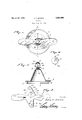
- Figure 1 is a top plan view of the device
- Fig. 2 is a vertical sectional view of the device on the line 2-2 of Fig. 1 looking in the direction indicated by the arrows,
- Fig. 3 is an enlarged detail plan view showing the blank of the pin wheel before being bent into shape
- Fig. i is an enlarged detail plan view showing the plate which forms the thrust bearing employed.
- the numeral 1 indicates a preferably frusto-conical base having its lower margin turned outwardly to provide a base flange 2, the outer edge of which is thickened to provide a reinforcing rim 3.
- a lug 4 mounted on the lower surface of the base flange 2 is a lug 4: and swingingly connected with the lug and extending transversely of the base is a pin 5 which is pointed at its free end.
- a U-shaped hook 6 mounted on the lower surface of the base flange diametrically of the lug 1 is a U-shaped hook 6 which normally receives the end portion of the pin 5.
- the hook and pin are utilized for connecting the device with the clothing and maintaining the device in an operative position.
- the upper end of the base is rounded and extending axially therethrough is a bushing 7 suitably fixed to the base. Formed integrallv on the upper end of said bushing is a washer 8. 7
- a pin wheel comprising blades 9 connected at their inner ends by a hub 10, which hub is provided with a centrally disposed opening 11 which forms a bearing.
- the pin wheel is preferably stamped from a blank of resilient sheet metal.
- Extending laterally from the hub 10 at right angles to the blades 9 and integral with said huh are oppositely disposed arms 12.
- Each of the arms is provided with a straight edge 13 and an inclined edge 14. the straight and inclined edges of the arms being disposed in diagonal relation to each other.
- Formed on the end portion of one of the arms 12 is a lug 15 and formed in the opposite arm 12 near its free end is a rectangular opening 16.
- Formed in the end portions of the arms 12 are openings 17.
- the arms 12 are rolled upwardly, as best shown in Fig.
- a substantially hexagonal plate 21 Overhanging the head 19 is a substantially hexagonal plate 21 having lugs 22 formed thereon, one of the lugs 22 being engaged in the opening 16 and bent inwardly.
- Formed in the uppermost of the arms 12 is an opening 23 and, as will be observed, the other of said lugs is engaged in said opening.
- the plate 21 will be held in position and the inner surface thereof will abut'the head 19 of the shaft 18 and provide a thrust bearing for the pin wheel so that the force of air currents acting on the pin wheel will be sustained by said plate while also the plate will hold the hub 10 of the pin wheel away from the washer S to insure free and easy rotation of the pin Wheel.
- the plate 21 is slightly concavo-convex in cross sectlon and substantially conforms to the shape of the rolled arms of the pin wheel.
- the device may be fastened to any desired article and when exposed to a draft of air, the pin wheel will be caused to rotate, thus causing a pleasing effect.
- the blades 9 may be colored in various shades so that the rotating movement of the pin wheel will cause various designs to be formed which will, of course, contribute to the attractiveness of the device. Attention is directed to the fact N that inasmuch as I have provided a thrust bearing for the p1n wheel, said pin wheel will and shaft will be prevented. It is to be noted,
- a device of the character described including a pin wheel having blades connected by a hub provided with an opening, said hub having laterally extending arms rolled so that their end portions are disposed in overlapping relation and said end portions being provided with registering openings in alignment with said first mentioned opening, a shaft extending through saidopenings and rotatably mounting the pin wheel, and a plateoverlying the shaft and provided with lugs connecting said plate with said arms, said plate coacting with the shaft to provide a thrust bearing for the pin wheel.
- a device of the character described including ashaft, a pin wheel rotatable thereon, and means carried by the pin wheel to coact with one end of the shaft and provide a thrust bearing for the pin wheel.
- .,V 3 device of the character described including 'Ziprn-wheel having arms, a shaft rotatably mounting the pin wheel and extending through said arms, and a plate connected to said arms to coact with one engl of the shaft and provide a thrust bearing for thepin wheel.
- a device of the character described including a base, a pin wheel rotatably mounted on the base and comprising blades connected at their inner ends by a hub having an opening and provided with arms, said arms being formed with openings, a shaft mounted on said base and extending through the openings, said shaft being formed with a head, and a plate connected with the arms and having its inner surface cooperating with the head :toprovide a thrust bearing, said head and thrust bearing coacting to limit the pin wheel against longitudinal shifting movement on the shaft.
- a device of the character described including a base, a pin wheel stamped from a blank of resilient material and having blades connected at their inner end portions by a hub, said hub being provided with laterally extending arms which are rolled so that their end portions overlap each other and overhang the central portion of the hub, a shaft e2:- tending through the hub and the overlapping end portions of said arms and being pro vided with a head, and a plate overlying the head, said plate and head cooperating to ii, iii the pin wheel against longitudinal dis,
Landscapes
- Sliding-Contact Bearings (AREA)
Description
March 29, 1932. J. F. BROWN ORNAMENT Filed Sept. 19, 1950 Jafiiz if Brawn).
Patented Mar. 29, 1932 JOHN F. BROWNQOFWEST WARWICK, RHODE ISLAND ORNAMENT Application filed September 19, 1930. Serial No. 483,076.
This invention relates to an improved orna- 11161113 for personal wear, and seeks, among other objects, to provide a device of this character, embodying a propeller, or pin wheel,
the main body of which may be stamped from a single piece of sheet material and bent into shape.
Another object of the invention is to provide a pin wheel employing three bearings,
one of which is a thrust bearing for preventing accidental inward shifting of said pin wheel and consequent wear upon the hub thereof.
A further object of the invention is to provide a pin wheel wherein the thrust bearing will also serve as a protecting cap and therefore prevent mutilation of the end of the pin wheel shaft employed.
A still further object of the invention is to provide a pin wheel which may be manufactured with the utmost facility and which will present a pleasing appearance. 7
Other and incidental objects of the invention not mentioned in the foregoing will appear during the course of the following description.
In the drawings,
Figure 1 is a top plan view of the device,
Fig. 2 is a vertical sectional view of the device on the line 2-2 of Fig. 1 looking in the direction indicated by the arrows,
Fig. 3 is an enlarged detail plan view showing the blank of the pin wheel before being bent into shape, and
"" Fig. i is an enlarged detail plan view showing the plate which forms the thrust bearing employed.
Referring now more particularly to the accompanying drawings, the numeral 1 indicates a preferably frusto-conical base having its lower margin turned outwardly to provide a base flange 2, the outer edge of which is thickened to provide a reinforcing rim 3.
I Mounted on the lower surface of the base flange 2 is a lug 4: and swingingly connected with the lug and extending transversely of the base is a pin 5 which is pointed at its free end. Mounted on the lower surface of the base flange diametrically of the lug 1 is a U-shaped hook 6 which normally receives the end portion of the pin 5. The hook and pin, of course, are utilized for connecting the device with the clothing and maintaining the device in an operative position. As best seen in Figure 2 of the drawings, the upper end of the base is rounded and extending axially therethrough is a bushing 7 suitably fixed to the base. Formed integrallv on the upper end of said bushing is a washer 8. 7
Associated with the base is a pin wheel comprising blades 9 connected at their inner ends by a hub 10, which hub is provided with a centrally disposed opening 11 which forms a bearing. The pin wheel is preferably stamped from a blank of resilient sheet metal. Extending laterally from the hub 10 at right angles to the blades 9 and integral with said huh are oppositely disposed arms 12. Each of the arms is provided with a straight edge 13 and an inclined edge 14. the straight and inclined edges of the arms being disposed in diagonal relation to each other. Formed on the end portion of one of the arms 12 is a lug 15 and formed in the opposite arm 12 near its free end is a rectangular opening 16. Formed in the end portions of the arms 12 are openings 17. The arms 12 are rolled upwardly, as best shown in Fig. 2 of the drawings, so that their end portions are disposed in overlapping relation withthe openings 17 in registration and in alignment with the open ng 11, the openin s 17 providing a bearing. The lug 15 is projected into the opening 16 and is bent to overlie the lower surface of the end portion of the lowermost arm so that 3.0- cidental displacement of the arms will be prevented. Extending through the bearings defined by the open ng 11 and the openings 17 of the arms 12 and through the washer 8 and the bushing 7 is a shaft or pin 18 and formed on the upper end of said shaft is a head 19. The opposite or lower end of said shaft is upset at 20, thereby preventing accidental outward movement of said shaft. The shaft M 18 is, of course, freely rotatableoii the shaft. Overhanging the head 19 is a substantially hexagonal plate 21 having lugs 22 formed thereon, one of the lugs 22 being engaged in the opening 16 and bent inwardly. Formed in the uppermost of the arms 12 is an opening 23 and, as will be observed, the other of said lugs is engaged in said opening. Thus the plate will be held in position and the inner surface thereof will abut'the head 19 of the shaft 18 and provide a thrust bearing for the pin wheel so that the force of air currents acting on the pin wheel will be sustained by said plate while also the plate will hold the hub 10 of the pin wheel away from the washer S to insure free and easy rotation of the pin Wheel. As best seen in F 2 .of the drawings, the plate 21 is slightly concavo-convex in cross sectlon and substantially conforms to the shape of the rolled arms of the pin wheel.
In use, the device may be fastened to any desired article and when exposed to a draft of air, the pin wheel will be caused to rotate, thus causing a pleasing effect. If desired, the blades 9 may be colored in various shades so that the rotating movement of the pin wheel will cause various designs to be formed which will, of course, contribute to the attractiveness of the device. Attention is directed to the fact N that inasmuch as I have provided a thrust bearing for the p1n wheel, said pin wheel will and shaft will be prevented. It is to be noted,
of course, that, while I have employed a. pin wheel comprising two blades, a greater number of blades may be employed if desired.
Having thus described the invention, I claim:
1. A device of the character described including a pin wheel having blades connected by a hub provided with an opening, said hub having laterally extending arms rolled so that their end portions are disposed in overlapping relation and said end portions being provided with registering openings in alignment with said first mentioned opening, a shaft extending through saidopenings and rotatably mounting the pin wheel, and a plateoverlying the shaft and provided with lugs connecting said plate with said arms, said plate coacting with the shaft to provide a thrust bearing for the pin wheel.
2. A device of the character describedincluding ashaft, a pin wheel rotatable thereon, and means carried by the pin wheel to coact with one end of the shaft and provide a thrust bearing for the pin wheel.
.,V 3 device of the character described including 'Ziprn-wheel having arms, a shaft rotatably mounting the pin wheel and extending through said arms, and a plate connected to said arms to coact with one engl of the shaft and provide a thrust bearing for thepin wheel.
4. A device of the character described including a base, a pin wheel rotatably mounted on the base and comprising blades connected at their inner ends by a hub having an opening and provided with arms, said arms being formed with openings, a shaft mounted on said base and extending through the openings, said shaft being formed with a head, and a plate connected with the arms and having its inner surface cooperating with the head :toprovide a thrust bearing, said head and thrust bearing coacting to limit the pin wheel against longitudinal shifting movement on the shaft.
5. A device of the character described including a base, a pin wheel stamped from a blank of resilient material and having blades connected at their inner end portions by a hub, said hub being provided with laterally extending arms which are rolled so that their end portions overlap each other and overhang the central portion of the hub, a shaft e2:- tending through the hub and the overlapping end portions of said arms and being pro vided with a head, and a plate overlying the head, said plate and head cooperating to ii, iii the pin wheel against longitudinal dis,
)lacement in either direction upon the shaft.
6. A device of the character described in cluding a base, a pin wheel hav'ng blades connected by a hub, said hub being formed. with arms having openings, a shaft extending through the hub and formed with a head, and a plate carried by the arms and having lugs extending through the openings and bent for securing the plate in position on the arms, said plate coacting with the shaft to provide a thrust bearing limiting the pin wheel against inward movement on the shaft.
In testimony whereof I affix my signature.
JOHN F. BRQIVN.
and;
Priority Applications (1)
| Application Number | Priority Date | Filing Date | Title |
|---|---|---|---|
| US483076A US1851806A (en) | 1930-09-19 | 1930-09-19 | Ornament |
Applications Claiming Priority (1)
| Application Number | Priority Date | Filing Date | Title |
|---|---|---|---|
| US483076A US1851806A (en) | 1930-09-19 | 1930-09-19 | Ornament |
Publications (1)
| Publication Number | Publication Date |
|---|---|
| US1851806A true US1851806A (en) | 1932-03-29 |
Family
ID=23918547
Family Applications (1)
| Application Number | Title | Priority Date | Filing Date |
|---|---|---|---|
| US483076A Expired - Lifetime US1851806A (en) | 1930-09-19 | 1930-09-19 | Ornament |
Country Status (1)
| Country | Link |
|---|---|
| US (1) | US1851806A (en) |
Cited By (6)
| Publication number | Priority date | Publication date | Assignee | Title |
|---|---|---|---|---|
| US2592876A (en) * | 1946-07-22 | 1952-04-15 | Clarence E Earle | Rotor and stator for fluid handling machines having surfaces coated with gold |
| US2679711A (en) * | 1951-06-28 | 1954-06-01 | Empress Novelty Company | Indian headdress with whirling feathers |
| US2728154A (en) * | 1952-10-08 | 1955-12-27 | Chicago Cardboard Company | Outdoor spinner display |
| US2923088A (en) * | 1958-11-07 | 1960-02-02 | Arvey Corp | Display spinner |
| US3359670A (en) * | 1966-06-29 | 1967-12-26 | Chester F Pyc | Advertising device |
| US4379813A (en) * | 1979-06-06 | 1983-04-12 | Newnham John H | Propellers and windmills |
-
1930
- 1930-09-19 US US483076A patent/US1851806A/en not_active Expired - Lifetime
Cited By (6)
| Publication number | Priority date | Publication date | Assignee | Title |
|---|---|---|---|---|
| US2592876A (en) * | 1946-07-22 | 1952-04-15 | Clarence E Earle | Rotor and stator for fluid handling machines having surfaces coated with gold |
| US2679711A (en) * | 1951-06-28 | 1954-06-01 | Empress Novelty Company | Indian headdress with whirling feathers |
| US2728154A (en) * | 1952-10-08 | 1955-12-27 | Chicago Cardboard Company | Outdoor spinner display |
| US2923088A (en) * | 1958-11-07 | 1960-02-02 | Arvey Corp | Display spinner |
| US3359670A (en) * | 1966-06-29 | 1967-12-26 | Chester F Pyc | Advertising device |
| US4379813A (en) * | 1979-06-06 | 1983-04-12 | Newnham John H | Propellers and windmills |
Similar Documents
| Publication | Publication Date | Title |
|---|---|---|
| US1851806A (en) | Ornament | |
| US2997344A (en) | Wheel cover | |
| US2629874A (en) | Graduation cap | |
| US1617318A (en) | Trolling lure | |
| US2377717A (en) | Compact | |
| US1645981A (en) | Scissors | |
| US2094326A (en) | Ornamental plate for wheels | |
| US1978272A (en) | Bottle cap and opener | |
| US1307960A (en) | Georgke lenox curtis | |
| US1412970A (en) | Attaching device | |
| US1494012A (en) | Ball retainer | |
| US2111986A (en) | Saw and saw collar | |
| US1407085A (en) | Marking button | |
| US2986791A (en) | Fastener | |
| US2109671A (en) | Hub cap for wheels | |
| US1705719A (en) | Shirt-collar backing | |
| US2923088A (en) | Display spinner | |
| US2371677A (en) | Draft regulator | |
| US2373380A (en) | Clasp for envelopes and the like | |
| JPH02128826U (en) | ||
| US584770A (en) | Badge | |
| US1926430A (en) | Collapsible hat | |
| US1985467A (en) | Toy pinwheel | |
| US1973061A (en) | Ribbon put-up | |
| US1695157A (en) | Finger ring |