US1851799A - Oil bath construction for rotaries - Google Patents
Oil bath construction for rotaries Download PDFInfo
- Publication number
- US1851799A US1851799A US358416A US35841629A US1851799A US 1851799 A US1851799 A US 1851799A US 358416 A US358416 A US 358416A US 35841629 A US35841629 A US 35841629A US 1851799 A US1851799 A US 1851799A
- Authority
- US
- United States
- Prior art keywords
- base
- wall
- bushing
- bearings
- flange
- Prior art date
- Legal status (The legal status is an assumption and is not a legal conclusion. Google has not performed a legal analysis and makes no representation as to the accuracy of the status listed.)
- Expired - Lifetime
Links
- 238000010276 construction Methods 0.000 title description 8
- 238000007789 sealing Methods 0.000 description 18
- 238000005553 drilling Methods 0.000 description 17
- 238000012856 packing Methods 0.000 description 9
- 230000002093 peripheral effect Effects 0.000 description 9
- 230000000630 rising effect Effects 0.000 description 4
- 239000012530 fluid Substances 0.000 description 3
- 238000011109 contamination Methods 0.000 description 2
- 239000000126 substance Substances 0.000 description 2
- 238000013459 approach Methods 0.000 description 1
- 238000004891 communication Methods 0.000 description 1
- 230000000694 effects Effects 0.000 description 1
- 239000000463 material Substances 0.000 description 1
- 238000000034 method Methods 0.000 description 1
- 230000000717 retained effect Effects 0.000 description 1
- 239000010802 sludge Substances 0.000 description 1
- XLYOFNOQVPJJNP-UHFFFAOYSA-N water Substances O XLYOFNOQVPJJNP-UHFFFAOYSA-N 0.000 description 1
Images

Classifications
-
- E—FIXED CONSTRUCTIONS
- E21—EARTH OR ROCK DRILLING; MINING
- E21B—EARTH OR ROCK DRILLING; OBTAINING OIL, GAS, WATER, SOLUBLE OR MELTABLE MATERIALS OR A SLURRY OF MINERALS FROM WELLS
- E21B3/00—Rotary drilling
- E21B3/02—Surface drives for rotary drilling
- E21B3/04—Rotary tables
-
- Y—GENERAL TAGGING OF NEW TECHNOLOGICAL DEVELOPMENTS; GENERAL TAGGING OF CROSS-SECTIONAL TECHNOLOGIES SPANNING OVER SEVERAL SECTIONS OF THE IPC; TECHNICAL SUBJECTS COVERED BY FORMER USPC CROSS-REFERENCE ART COLLECTIONS [XRACs] AND DIGESTS
- Y10—TECHNICAL SUBJECTS COVERED BY FORMER USPC
- Y10T—TECHNICAL SUBJECTS COVERED BY FORMER US CLASSIFICATION
- Y10T74/00—Machine element or mechanism
- Y10T74/19—Gearing
- Y10T74/19642—Directly cooperating gears
- Y10T74/1966—Intersecting axes
- Y10T74/19665—Bevel gear type
Definitions
- This invention relates to rotary well drilling apparatus and more particularly to the construction of the drilling table of the rotary.
- An important object of the invention is to provide in a device of this character a construction such that the operating parts of the rotary table including the bearings and gearing may be so housed that they can be kept in a bath of oil, preventing any contamination thereof.
- a further object of the invention is the production in apparatus of this character of an arrangementsuch that the inner section of the complete drilling table when removed will provide access to the bearings supporting the outer table and thus enable the same to be cleansed by the use of steam, compressed air or the like, of any foreign substance which may have collected therein.
- a still further object of the invention is to provide apparatus of this character of such structure that it may be applied to rotary well drilling apparatus constructed in accordance with my prior Patent No. 1,580,002, issued April 6, 1926, for rotary well drilling apparatus.
- Another object of the invention is. to provide a construction such that all fluids leaking from the drilling swivel or joints of the drilling apparatus lying above the table are withheld from entry to the housing of the bearings and gearing. 7
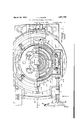
- Figure 1 is a plan view partially in section of rotary well drilling apparatus constructed in accordance with my invention
- Figure 2 is a section on line 2'2 of Figure 1;
- FIG. 3 is a fragmentary detailed sec:
- Figure 4 is a fragmentary section on the line ttof Figure 2;
- Figure 5 is a fragmentarysection on the line 5-5 of Figure 2.
- the numeral 10 generally designates supporting skids, and 11 the base supported thereby.
- This base has a central opening defined by an upstanding flange 12, and upon the base immediately outward of this flange a roller bearing track 13 is disposed.
- an intermediate bushing 15 On this track, by rollers 14, is supported an intermediate bushing 15, having a central bore, the lower portion of which has the same interior diameter as the interior diameter of flange 12, and the lower face of which at the bore closely approaches the upper edge of the flange 12.
- the upper portion of the bore is conical, as indicated at 16, and is formed in the face thereof with teeth 17 adapted to mesh with teeth 18 formed upon a skirt 20 depending from an inner table element or grief stem drive bushing support 19, which seats upon the upper surface of the bushing.
- the upper portion of the skirt 20 fits Within the conic portion of the bore and is provided with the teeth 18, and the lower portion fits against the vertical portion of the bore of the intermediate bushing and against the flange 12.
- the lower portion of the outer face of this skirt engages against a packing 21, which effects a seal between the skirt and the flange.
- the upper surface of the intermediate bushing is formed with an annular recess 22 and in the base of this groove is provided a roller track 23.
- This track carries rollers 24, which support an outer table element 25, this outer table element having at the inner margin of the upper surface thereof an upstanding flange 26, over which extends a depending flange 27 carried by the inner table element.
- the upper surface of the inner table element is at a slightly higher elevation than the outer table, and flange 27 extends downwardly below the upper end of flange 26, so that any sludge flowing from the surface of the inner table over table 25 will not pass between adjacent faces of the tables 19 and 25 and thus obtain access to the groove 22 and the roller bearings 24, or to the bearings 14.
- the outer marginal portion of the base is defined by an upstanding wall 28 inv which is mounted a bearing '29 receiving the drive shaft 30, the inner end of which is provided Cit face of the wall section will act to with a pinion 31 having driving engagement with teeth 32 formed upon the under surface at the outer portion of the outer table.
- the outer face of the outer table is provided with a circumferentially extending groove 33, those portions of the outer face of the table lying above this groove projecting slightly beyond those lying below, as at 34 and having formed in the lower face thereof a packing groove 35.
- the upstanding wall 28 of the base is preferabl 1 formed in two sections, one of which is directly attached to the base and the other of which, as indicated at 36, is bolted or otherwise secured to the first named section.
- a combined hold down and sealing ring 37 which is formed in two sections securely bolted to the upper sur- 36, and have their ends connected by a packing indicated at 38.
- Ring 37 is vertically offset intermediate its inner and outer edges, the inner edge thereof being disposed at a higher level and bearing against the upper wall of the groove, and against the packing 38.
- This ring serves to continue the outward movement of any water or slush which may be deposited upon the table and permit the same to pass down the side walls and so to the ground.
- the apparatus illustrated is amodification of the arrangement shown in my prior patent, in so far as the use of the intermediate bushing and the inner and outer tables is concerned.
- the outer table is provided with a circular series of clutch teeth 39 with which teeth formed on the side face of a clutch ring lOare slidably engaged for vertical movement.
- this clutch ring a0 is likewise provided with teeth, indicated at 41, and these teeth overlie teeth formed in the upper surface ofthe intermediate bushing between the recess 22 and the outer wall of thisbushing. These teeth are cut to substantially the same depth as the rollers 24, and place the groove 22 in communication with the outer face of the bushing,
- the outer f aceiof the intermediate bushing is provided with circumferentially spaced sockets 42, which are engageable by a latch element 43 rectilinearly moveable througlrthe wall28 andhaving sealing engagementtherewithatthe point ofitspassagetherethrough.
- the ring 40 which as in the case of, the
- each standard 43a operates within a guide 46 through, which is directed a wedge element 47', having connected thereto a shifting rod 28 passing through the wall 28 and having sealing engagement therewith, as at 49.
- These wedges which are two in number are arranged at opposite sides of the table structure and may be operated by a common lever connected thereto by links, as at 51.
- Shaft 30 at the point of its passage through the bearin is provided with s als 52, preventing loss of oil from the housing provided by the structurejust described, and accordingly, oil may be introduced to this housing, at 53, and will be retained therein just long as the inner table remains in position to complete the housing structurei
- a sectional grief or drill stein drive bushing structure comprising the bushings 54-, 55 and 56 such as illustrated in my Patent No. 1,771,391 grant ed July 29, 1930 on locking devices for internal bushings, a structure may be provided wherein all 1i (elihood of any contamination of thecontained oil by the mud and slush is avoided, and a readily manipulatable structure provided.
- a base having a central openingdefined by an upstanding fiange, an outertable rotatably supported on said base, an outer wall rising from said base the outer table having an annular recess formed inthe peripheral wall. thereof, a flexiblepaclzing ring secured tothe upper end of the base wall and having its inner edge projecting into and having sealing engagement with the walls of said recess, means for driving the table including a shaft e7;- tending through and sealedtosaid wallthe table having a central opening, and a drill stem drive bushing support seated in the opening of the outer table and having sealing enga gement with said-flange to therebycombine with-the outer table, the ring, said wall and the base to produce oil tight housing.
- a base having a central opening, bearings carried by saidbase, a table rotatably supported on said bearings, an outer wall rising from the base,
- the outer table having a roove formed in the peripheral wall thereof, a packing ring secured to the upper end of the base wall and having its inner edge projecting into and having sealing engagement with the walls of said groove, means for driving the table including a shaft extending through said wall and sealed thereto, said table having a central opening, a drill stem drive bushing support seated in said central opening, and a sealing connection between the lower end of the outer wall of said drill stem drive bushing support and said base.
- a base having a central opening, bearings carried by said base, a table rotatably supported on said bearings, an outer wall rising from the base, the table having an annular recess formed in the peripheral wall thereof, a packing ring secured to the upper end of the base wall and having its inner edge projecting into and having sealing engagement with the walls of said recess, means for driving the table including a shaft extending through said wall and sealed thereto, said table having a central opening, a drill stem drive bush 7 ing support seated in said central opening,
- the drill stem drive bushing support having a flange overlying said rim and provided with a downturned terminal, a laterally extending flange, and manually operable locking devices to engage the drill stem drive bushing support against vertical movement.
- a base having a central opening, bearings supported by the base and surrounding the opening, a bushing rotatably supported on said bearings, a table rotatably supported on the bushing, means shiftable to connect or disconnect said table and bushing, a wall arising from the base, the table having an annular recess formed in the peripheral wall thereof, a packing ring secured to the upper end of the base wall and having its inner edge projecting into and having sealing engagement with the walls of said recess, means for driving the table including a shaft extending through and sealed to said wall the bushing and table having central openings, a drill stem drive bushing support engaged in the openings of the table, the drill stem drive bushing support and the table having sealing engagement with each other, the bushing havingsealing engagement with the base, and the drill stem drive bushing support having engagement with the bushing to prevent relative rotation thereof.
- a base having a central opening, bearings supported by the base and surrounding the opening, a
- means for driving the table including a shaft extending through and sealed to said wall, the bushing and table having central openings, a drill stem drive bushing support engaged in the openings of the table, bushing and base having sealing engagement with the base and engagement with the bushing preventing relative rotation thereof, the bearings of the base being accessible to a fluid pressure blast uponremoval of said drill stem drive bushing support.
- a base having a central opening, and an outer peripheral wall extending upward from the base, bearings carried by said base, a table rotatably supported on said bearings, the table having an annularrecess formed in the peripheral wall thereof, a flexible packing ring secured to the base wall and having its inner end projecting into and having sealing engagement with the walls of said recess, means for driving the table including a shaft extending through said peripheral wall and sealed thereto, the table having a central opening, a drill stem drive bushing support removably seated in the central opening, the lower end of-said drive bushing support and the base having sealed engagement with each other, the bearings of said base being thus accessible for cleansing by a fluid pressure jet uponremoval of the drill stem drive bushing support.
- a base having a central opening defined by an upstanding wall, an outer upstanding wall formed upon said base, bearings carried by said base, an annular internal bushing supported by said bearings, an annular table supported on said bearin gs and extending outward beyond the internal bushing, the peripheral face of the table being annularly recessed, a packing ring mounted upon the outer wall of the table and extending into said recess, a shaft extending through the outer wall and sealed therein and having a gear wheel engaging the outer table to rotate it, the upper face of the table being higher than the upper face of the wall on the base, and an inner table or drill stem drive bushing support disposed within the opening of the inner table and having a skirt extending downward through the opening in the internal bushing, and having sealed engagement with the upwardly extending central flange of the base, the upper end of said support being formed with an annular fiangeextending outward over the upper ta ce o 1 ,8.
- 11 basehaving a central opening and an upstanding outer peripheral wall, a table rotatably supported upon the base inward ofthe outer wall and having a circumferential recess dis.- posed in a horizontal plane and above the upper surface of the outer wall, and a combined hold-down and sealing ring of flexible material extending into and having sealing engagement with the upper and lower walls of the circumferential recess of the table and extending downward to the upper surface of 15 the outer wall 9.
- a base having a central opening, bearings carried by said base, an outer table rotatably supported upon said bearings, the outer table hav- 539 ing an upwardly extending flange on its upper surface, a wall rising from the base and extending around said outer table, the outer table having a circumferential recess disposed above the upper surface of the outer wall a combined hold down sealing ring extending into and having sealing engagement with the walls of the circumferential recess and extending outwardly over and engaging with the upper surface of the outer wall, 39 means for driving the table including a shaft extending through said outer wall and sealed thereto, said outer table having a central opening, an inner table seated in said central opening and extending above the outer table and having a flange extending outward and downward over the flange on-the outer table, there being a sealing connection between the lower end of the inner table and said base.
Landscapes
- Engineering & Computer Science (AREA)
- Life Sciences & Earth Sciences (AREA)
- Geology (AREA)
- Mining & Mineral Resources (AREA)
- Mechanical Engineering (AREA)
- Physics & Mathematics (AREA)
- Environmental & Geological Engineering (AREA)
- Fluid Mechanics (AREA)
- General Life Sciences & Earth Sciences (AREA)
- Geochemistry & Mineralogy (AREA)
- Earth Drilling (AREA)
Description
March 29, 1932. L. J. BLACK OIL BATH CONSTRUCTION FOR ROTARIES gmmu L JfiZao/n Filed ril 26, ,1929 2 Sheets-Sheet March 29,v 1932.
L J. BLACK 01L. BATH CONSTRUCTION FOR ROTARIE Filed April 26, 1929 2 Sheets-Sheet 2 xiv Patented Mar. 29, 1932 PATENT OFFICE LEE J. BLACK, OFBEAUMONT, 'rnxas OIL BATH CONSTRUCTION FOR ROTARIES Application filed April 26,
This invention relates to rotary well drilling apparatus and more particularly to the construction of the drilling table of the rotary.
An important object of the invention is to provide in a device of this character a construction such that the operating parts of the rotary table including the bearings and gearing may be so housed that they can be kept in a bath of oil, preventing any contamination thereof.
A further object of the invention is the production in apparatus of this character of an arrangementsuch that the inner section of the complete drilling table when removed will provide access to the bearings supporting the outer table and thus enable the same to be cleansed by the use of steam, compressed air or the like, of any foreign substance which may have collected therein.
A still further object of the invention is to provide apparatus of this character of such structure that it may be applied to rotary well drilling apparatus constructed in accordance with my prior Patent No. 1,580,002, issued April 6, 1926, for rotary well drilling apparatus.
Another object of the invention is. to provide a construction such that all fluids leaking from the drilling swivel or joints of the drilling apparatus lying above the table are withheld from entry to the housing of the bearings and gearing. 7
These and other objects I attain by the con struction shown in the accompanying drawings wherein for the urpose of illustration I have shown a pre erred embodiment of my invention and wherein:
Figure 1 is a plan view partially in section of rotary well drilling apparatus constructed in accordance with my invention;
Figure 2 is a section on line 2'2 of Figure 1;
Figure 3 is a fragmentary detailed sec:
- tional view showing the method of mountlng and operating the shiftingring;
Figure 4 is a fragmentary section on the line ttof Figure 2;
Figure 5 is a fragmentarysection on the line 5-5 of Figure 2.
1929. Serial No. 358,416.
Referring now more particularly to the drawings, the numeral 10 generally designates supporting skids, and 11 the base supported thereby. This base has a central opening defined by an upstanding flange 12, and upon the base immediately outward of this flange a roller bearing track 13 is disposed. On this track, by rollers 14, is supported an intermediate bushing 15, having a central bore, the lower portion of which has the same interior diameter as the interior diameter of flange 12, and the lower face of which at the bore closely approaches the upper edge of the flange 12. The upper portion of the bore is conical, as indicated at 16, and is formed in the face thereof with teeth 17 adapted to mesh with teeth 18 formed upon a skirt 20 depending from an inner table element or grief stem drive bushing support 19, which seats upon the upper surface of the bushing. The upper portion of the skirt 20 fits Within the conic portion of the bore and is provided with the teeth 18, and the lower portion fits against the vertical portion of the bore of the intermediate bushing and against the flange 12. The lower portion of the outer face of this skirt engages against a packing 21, which effects a seal between the skirt and the flange.
The upper surface of the intermediate bushing is formed with an annular recess 22 and in the base of this groove is provided a roller track 23. This track carries rollers 24, which support an outer table element 25, this outer table element having at the inner margin of the upper surface thereof an upstanding flange 26, over which extends a depending flange 27 carried by the inner table element.
The upper surface of the inner table element is at a slightly higher elevation than the outer table, and flange 27 extends downwardly below the upper end of flange 26, so that any sludge flowing from the surface of the inner table over table 25 will not pass between adjacent faces of the tables 19 and 25 and thus obtain access to the groove 22 and the roller bearings 24, or to the bearings 14.
The outer marginal portion of the base is defined by an upstanding wall 28 inv which is mounted a bearing '29 receiving the drive shaft 30, the inner end of which is provided Cit face of the wall section will act to with a pinion 31 having driving engagement with teeth 32 formed upon the under surface at the outer portion of the outer table. The outer face of the outer table is provided with a circumferentially extending groove 33, those portions of the outer face of the table lying above this groove projecting slightly beyond those lying below, as at 34 and having formed in the lower face thereof a packing groove 35.
The upstanding wall 28 of the base is preferabl 1 formed in two sections, one of which is directly attached to the base and the other of which, as indicated at 36, is bolted or otherwise secured to the first named section. Upon. the upper surface of this last named section which is disposed slightly below the level of the groove 33, I place a combined hold down and sealing ring 37, which is formed in two sections securely bolted to the upper sur- 36, and have their ends connected by a packing indicated at 38. Ring 37 is vertically offset intermediate its inner and outer edges, the inner edge thereof being disposed at a higher level and bearing against the upper wall of the groove, and against the packing 38.
This ring serves to continue the outward movement of any water or slush which may be deposited upon the table and permit the same to pass down the side walls and so to the ground.
The apparatus illustrated is amodification of the arrangement shown in my prior patent, in so far as the use of the intermediate bushing and the inner and outer tables is concerned. As set forth in this prior patent, the outer table is provided with a circular series of clutch teeth 39 with which teeth formed on the side face of a clutch ring lOare slidably engaged for vertical movement.
The under surface of this clutch ring a0 is likewise provided with teeth, indicated at 41, and these teeth overlie teeth formed in the upper surface ofthe intermediate bushing between the recess 22 and the outer wall of thisbushing. These teeth are cut to substantially the same depth as the rollers 24, and place the groove 22 in communication with the outer face of the bushing,
It will be obvious that by removing the inner table access may be very readily had to the rollers 14, so that they may be cleaned by an air jet, and it will'also be obvious jet may be directed into the groove 22 and force any foreign substance upon the rollers 2 through the-openings provided between adjacent teeth of the bushing. The outer f aceiof the intermediate bushing ;is provided with circumferentially spaced sockets 42, which are engageable by a latch element 43 rectilinearly moveable througlrthe wall28 andhaving sealing engagementtherewithatthe point ofitspassagetherethrough.
The ring 40, which as inthe case of, the
corresponding ring of'niy prior patent above that a mentioned, is vertically shiftable so that it may be engaged with the outer table section alone, or with the outer table section and intermediate bushing, is at present shown as supported upon vertically shiftable standards 43a, the upper ends of which have T heads 44: provided with rollers 45 engaging the under surface of the outer portion of the ring. Each standard 43a operates within a guide 46 through, which is directed a wedge element 47', having connected thereto a shifting rod 28 passing through the wall 28 and having sealing engagement therewith, as at 49., These wedges, which are two in number are arranged at opposite sides of the table structure and may be operated by a common lever connected thereto by links, as at 51. Shaft 30, at the point of its passage through the bearin is provided with s als 52, preventing loss of oil from the housing provided by the structurejust described, and accordingly, oil may be introduced to this housing, at 53, and will be retained therein just long as the inner table remains in position to complete the housing structurei By employing in the inner table a sectional grief or drill stein drive bushing structure comprising the bushings 54-, 55 and 56 such as illustrated in my Patent No. 1,771,391 grant ed July 29, 1930 on locking devices for internal bushings, a structure may be provided wherein all 1i (elihood of any contamination of thecontained oil by the mud and slush is avoided, and a readily manipulatable structure provided.
It will be obvious that this structure is capable of a very considerable range of change andinodhication without in any man ner departingfrom the spirit of the invention, and I accordingly do not limit myselfto such specific structure except as hereinafter claimed.
I' claim:
1. In rotary well drilling apparatus, a base having a central openingdefined by an upstanding fiange, an outertable rotatably supported on said base, an outer wall rising from said base the outer table having an annular recess formed inthe peripheral wall. thereof, a flexiblepaclzing ring secured tothe upper end of the base wall and having its inner edge projecting into and having sealing engagement with the walls of said recess, means for driving the table including a shaft e7;- tending through and sealedtosaid wallthe table having a central opening, and a drill stem drive bushing support seated in the opening of the outer table and having sealing enga gement with said-flange to therebycombine with-the outer table, the ring, said wall and the base to produce oil tight housing.
2. In rotary well drilling apparatus, a base having a central opening, bearings carried by saidbase, a table rotatably supported on said bearings, an outer wall rising from the base,
ers.-
the outer table having a roove formed in the peripheral wall thereof, a packing ring secured to the upper end of the base wall and having its inner edge projecting into and having sealing engagement with the walls of said groove, means for driving the table including a shaft extending through said wall and sealed thereto, said table having a central opening, a drill stem drive bushing support seated in said central opening, and a sealing connection between the lower end of the outer wall of said drill stem drive bushing support and said base.
3. In rotary well drilling apparatus, a base having a central opening, bearings carried by said base, a table rotatably supported on said bearings, an outer wall rising from the base, the table having an annular recess formed in the peripheral wall thereof, a packing ring secured to the upper end of the base wall and having its inner edge projecting into and having sealing engagement with the walls of said recess, means for driving the table including a shaft extending through said wall and sealed thereto, said table having a central opening, a drill stem drive bush 7 ing support seated in said central opening,
(iii
and a sealing connection between the lower end of the outer wall of said drill stem drive bushing support and said base, the upper surface of said table at'the inner edge thereof having an upstanding rim, the drill stem drive bushing support having a flange overlying said rim and provided with a downturned terminal, a laterally extending flange, and manually operable locking devices to engage the drill stem drive bushing support against vertical movement.
4. In rotary well drilling apparatus, a base having a central opening, bearings supported by the base and surrounding the opening, a bushing rotatably supported on said bearings, a table rotatably supported on the bushing, means shiftable to connect or disconnect said table and bushing, a wall arising from the base, the table having an annular recess formed in the peripheral wall thereof, a packing ring secured to the upper end of the base wall and having its inner edge projecting into and having sealing engagement with the walls of said recess, means for driving the table including a shaft extending through and sealed to said wall the bushing and table having central openings, a drill stem drive bushing support engaged in the openings of the table, the drill stem drive bushing support and the table having sealing engagement with each other, the bushing havingsealing engagement with the base, and the drill stem drive bushing support having engagement with the bushing to prevent relative rotation thereof.
5. In rotary well drilling apparatus, a base having a central opening, bearings supported by the base and surrounding the opening, a
the walls of said recess, means for driving the table including a shaft extending through and sealed to said wall, the bushing and table having central openings, a drill stem drive bushing support engaged in the openings of the table, bushing and base having sealing engagement with the base and engagement with the bushing preventing relative rotation thereof, the bearings of the base being accessible to a fluid pressure blast uponremoval of said drill stem drive bushing support.
' 6. In a rotary well drilling apparatus, a base having a central opening, and an outer peripheral wall extending upward from the base, bearings carried by said base, a table rotatably supported on said bearings, the table having an annularrecess formed in the peripheral wall thereof, a flexible packing ring secured to the base wall and having its inner end projecting into and having sealing engagement with the walls of said recess, means for driving the table including a shaft extending through said peripheral wall and sealed thereto, the table having a central opening, a drill stem drive bushing support removably seated in the central opening, the lower end of-said drive bushing support and the base having sealed engagement with each other, the bearings of said base being thus accessible for cleansing by a fluid pressure jet uponremoval of the drill stem drive bushing support.
7. In a rotary well drilling apparatus, a base having a central opening defined by an upstanding wall, an outer upstanding wall formed upon said base, bearings carried by said base, an annular internal bushing supported by said bearings, an annular table supported on said bearin gs and extending outward beyond the internal bushing, the peripheral face of the table being annularly recessed, a packing ring mounted upon the outer wall of the table and extending into said recess, a shaft extending through the outer wall and sealed therein and having a gear wheel engaging the outer table to rotate it, the upper face of the table being higher than the upper face of the wall on the base, and an inner table or drill stem drive bushing support disposed within the opening of the inner table and having a skirt extending downward through the opening in the internal bushing, and having sealed engagement with the upwardly extending central flange of the base, the upper end of said support being formed with an annular fiangeextending outward over the upper ta ce o 1 ,8. In a rotary well drilling apparatus, 11 basehaving a central opening and an upstanding outer peripheral wall, a table rotatably supported upon the base inward ofthe outer wall and having a circumferential recess dis.- posed in a horizontal plane and above the upper surface of the outer wall, and a combined hold-down and sealing ring of flexible material extending into and having sealing engagement with the upper and lower walls of the circumferential recess of the table and extending downward to the upper surface of 15 the outer wall 9. In a rotarywell drilling apparatus, a base having a central opening, bearings carried by said base, an outer table rotatably supported upon said bearings, the outer table hav- 539 ing an upwardly extending flange on its upper surface, a wall rising from the base and extending around said outer table, the outer table having a circumferential recess disposed above the upper surface of the outer wall a combined hold down sealing ring extending into and having sealing engagement with the walls of the circumferential recess and extending outwardly over and engaging with the upper surface of the outer wall, 39 means for driving the table including a shaft extending through said outer wall and sealed thereto, said outer table having a central opening, an inner table seated in said central opening and extending above the outer table and having a flange extending outward and downward over the flange on-the outer table, there being a sealing connection between the lower end of the inner table and said base.
In testimony whereof I aflix my signature.
, LEE J. BLACK.
Priority Applications (1)
| Application Number | Priority Date | Filing Date | Title |
|---|---|---|---|
| US358416A US1851799A (en) | 1929-04-26 | 1929-04-26 | Oil bath construction for rotaries |
Applications Claiming Priority (1)
| Application Number | Priority Date | Filing Date | Title |
|---|---|---|---|
| US358416A US1851799A (en) | 1929-04-26 | 1929-04-26 | Oil bath construction for rotaries |
Publications (1)
| Publication Number | Publication Date |
|---|---|
| US1851799A true US1851799A (en) | 1932-03-29 |
Family
ID=23409567
Family Applications (1)
| Application Number | Title | Priority Date | Filing Date |
|---|---|---|---|
| US358416A Expired - Lifetime US1851799A (en) | 1929-04-26 | 1929-04-26 | Oil bath construction for rotaries |
Country Status (1)
| Country | Link |
|---|---|
| US (1) | US1851799A (en) |
-
1929
- 1929-04-26 US US358416A patent/US1851799A/en not_active Expired - Lifetime
Similar Documents
| Publication | Publication Date | Title |
|---|---|---|
| US2853274A (en) | Rotary table and pressure fluid seal therefor | |
| US1813402A (en) | Pressure drilling head | |
| US3285352A (en) | Rotary air drilling head | |
| US4157186A (en) | Heavy duty rotating blowout preventor | |
| US1391626A (en) | Drill-head for well-driling apparatus | |
| US3128614A (en) | Drilling head | |
| US3477746A (en) | Multiline swivel and mounting system | |
| US3464632A (en) | Hydraulic tank cleaning apparatus | |
| US2176323A (en) | Swivel | |
| US1851799A (en) | Oil bath construction for rotaries | |
| US2120132A (en) | Method and apparatus for cleaning wells | |
| US2088418A (en) | Hydraulic swivel | |
| US3467202A (en) | Hydraulically driven power head | |
| US1760224A (en) | Swivel | |
| US2346380A (en) | Swivel | |
| US2072936A (en) | Rotary machine | |
| US2157728A (en) | Speed-up and speed-down for rotaries | |
| US2171176A (en) | Oil bath rotary | |
| US2558990A (en) | Rotary hydraulic swivel | |
| US2600555A (en) | Drive shaft assembly for rotary well-drilling apparatus | |
| US2205269A (en) | Rotary machine | |
| US1734223A (en) | Balanced thrust bearing | |
| US1739803A (en) | Line-shaft-bearing-lubricating device | |
| US2067921A (en) | Rotary machine | |
| US2189912A (en) | Gear box for drilling apparatus |