US1851797A - Automatic controls for airplanes - Google Patents
Automatic controls for airplanes Download PDFInfo
- Publication number
- US1851797A US1851797A US522733A US52273331A US1851797A US 1851797 A US1851797 A US 1851797A US 522733 A US522733 A US 522733A US 52273331 A US52273331 A US 52273331A US 1851797 A US1851797 A US 1851797A
- Authority
- US
- United States
- Prior art keywords
- craft
- airplane
- rods
- airplanes
- automatic controls
- Prior art date
- Legal status (The legal status is an assumption and is not a legal conclusion. Google has not performed a legal analysis and makes no representation as to the accuracy of the status listed.)
- Expired - Lifetime
Links
- 230000007246 mechanism Effects 0.000 description 5
- 241001439211 Almeida Species 0.000 description 2
- 238000010276 construction Methods 0.000 description 2
- 230000009471 action Effects 0.000 description 1
- 230000008859 change Effects 0.000 description 1
- 230000009194 climbing Effects 0.000 description 1
- 230000000881 depressing effect Effects 0.000 description 1
- 230000000994 depressogenic effect Effects 0.000 description 1
- IWEDIXLBFLAXBO-UHFFFAOYSA-N dicamba Chemical compound COC1=C(Cl)C=CC(Cl)=C1C(O)=O IWEDIXLBFLAXBO-UHFFFAOYSA-N 0.000 description 1
- 230000009189 diving Effects 0.000 description 1
- 230000000694 effects Effects 0.000 description 1
- 230000003028 elevating effect Effects 0.000 description 1
- 238000004519 manufacturing process Methods 0.000 description 1
- 230000007935 neutral effect Effects 0.000 description 1
- 229920000136 polysorbate Polymers 0.000 description 1
Images
Classifications
-
- B—PERFORMING OPERATIONS; TRANSPORTING
- B64—AIRCRAFT; AVIATION; COSMONAUTICS
- B64C—AEROPLANES; HELICOPTERS
- B64C17/00—Aircraft stabilisation not otherwise provided for
Definitions
- This invention relates to improvements in automatic controls for airplanes.
- the principal object of this invention is to provide means whereby the stability of the airplane will be automatically controlled thru the efi'ect of the wind passingover a plurality of movable surfaces which are inter-connected so as to control the position of the steering or elevating rudders.
- a further object is to produce a device of this character which may be attached to any standard form of air craft without materially altering its construction.
- a further object is to provide a device which is economical to manufacture.
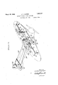
- Figure 1 is a perspective view of my control arrangement and showing the airplane in dotted lines
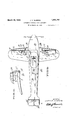
- Figure 2 is a top plan view of an airplane having my control attached thereto, and
- Figure 3 is an end elevation of one of the wings of an airplane.
- the aviator in order to maintain an airplane upon a proper flight, it is necessary for the aviator to constantly actuate the various steering surfaces such as the tail, fin, the vertical rudder and the ailerons.
- My device consists in positioning preferably upon the upper surface of the airplane wings independent surfaces, which surfaces are at all times trailing in the wind, and being inter-connected, this trailing effect, should the direction of the wind change, will immediately cause movement of the steering mechanism to thereby automatically bring the ship back to its normal flying position.
- the r d 6 has a vertical shaft 9 the pilot causes the craft to move out of the 100 which is shown at 5 is supported at its forward edge on a rod 6 which is journalled in standards 7 and 8, which standards are secured to the upper surface of the airplane formed integral therewith, to which is freely attached a vertical fin 11.
- the aileron 5 and the fin 11 are connected together thru the medium of arms 12 and 13 respectively, be-
- the rod 6 has a lever 16 attached thereto to which is pivotally attached a link17 and is in turn pivoted as at 18 to the arm 19 of an actuating bar 21.
- This actuating bar is rotated thru the medium of a projection 22 to which is pivoted a link 23, the opposite end of which is pivoted as at 24 to a walking beam 26.
- the opposite end of this Walking beam is connected by a link 27 to the stick 28.
- the center of the walking beam is connected by a link 29 to the elevator 31.
- the actuating bar 21 extends across the fuselage and is connected to the mechanism positioned upon the opposite side of the ship to that just described.
- the vertically pivoted tail .32 is connected by the customary cables 33 and 34 which pass over suitable sheaves 36 and 37 respectively, and are thence reeved around a pulley 38 which is rotatable thru the medium of the steering wheel 39.
- the stick 28 is pivoted as at 41, as is customary practise.
- control of the elevator 31 is maintained so that the elevator may be actuated by either the ailerons or by the stick.
- I claim 1 In a device of the character described adapted to be attached to an airplane, a pair of spaced horizontal rods, an aileron freely supported on each of said rods, a vertically disposed fin freely pivoted on each of said rods, each of'said fins being connected to its adjacent aileron whereby movement of said fins about their vertical pivots will cause pivotal movement of said ailerons about their horizontal rods, an actuating lever extending between said spaced rods and link mechanism connected to said actuating bar and said hori-. zontal rods whereby said horizontal rods will be moved in' unison.
Landscapes
- Engineering & Computer Science (AREA)
- Aviation & Aerospace Engineering (AREA)
- Toys (AREA)
Description
I March 29, 1932.
J. v. ALMEIDA AUTOMATIC CONTROLS FOR AIRPLANES Filed March 14, 1931 2 Sheets-Sheet 1 H muHnm INVENTOR. JOHN VALMFEI A ATTORNEYS March 29, 1932. J. v. ALMEIDA- AUTOMATIC CONTROLS FOR AIRPLANES Filed March 14, 1931 2 Sheets-Sheet 2 INVENTOR. J OHN K AZM'EJDA %6zjc%mw@ ATTORNEYS ill Patented Mar. 29, 1932 PATENT OFFICE JOHN V. ALMEIDA, OF NEWMAN, CALIFORNIA AUTOMATIC CONTROLS FOR Application filed March 14, 1931. Serial No. 522,738.
This invention relates to improvements in automatic controls for airplanes.
The principal object of this invention is to provide means whereby the stability of the airplane will be automatically controlled thru the efi'ect of the wind passingover a plurality of movable surfaces which are inter-connected so as to control the position of the steering or elevating rudders.
A further object is to produce a device of this character which may be attached to any standard form of air craft without materially altering its construction.
A further object is to provide a device which is economical to manufacture.
Other objects and advantages will be apparent during the course of the following description.
In the accompanying drawings forming a part of this specification and in which like numerals are employed to designate like parts throughout the same,
Figure 1 is a perspective view of my control arrangement and showing the airplane in dotted lines,
Figure 2 is a top plan view of an airplane having my control attached thereto, and
Figure 3 is an end elevation of one of the wings of an airplane.
At the present time, in order to maintain an airplane upon a proper flight, it is necessary for the aviator to constantly actuate the various steering surfaces such as the tail, fin, the vertical rudder and the ailerons.
My device consists in positioning preferably upon the upper surface of the airplane wings independent surfaces, which surfaces are at all times trailing in the wind, and being inter-connected, this trailing effect, should the direction of the wind change, will immediately cause movement of the steering mechanism to thereby automatically bring the ship back to its normal flying position. As both of the ailerons and their attached mechanism are alike, but one will be described. The aileron wing. The r d 6 has a vertical shaft 9 the pilot causes the craft to move out of the 100 which is shown at 5 is supported at its forward edge on a rod 6 which is journalled in standards 7 and 8, which standards are secured to the upper surface of the airplane formed integral therewith, to which is freely attached a vertical fin 11. The aileron 5 and the fin 11 are connected together thru the medium of arms 12 and 13 respectively, be-
tween which a link 14 is interposed. The rod 6 has a lever 16 attached thereto to which is pivotally attached a link17 and is in turn pivoted as at 18 to the arm 19 of an actuating bar 21. This actuating bar is rotated thru the medium of a projection 22 to which is pivoted a link 23, the opposite end of which is pivoted as at 24 to a walking beam 26. The opposite end of this Walking beam is connected by a link 27 to the stick 28. The center of the walking beam is connected by a link 29 to the elevator 31. The actuating bar 21 extends across the fuselage and is connected to the mechanism positioned upon the opposite side of the ship to that just described. The vertically pivoted tail .32 is connected by the customary cables 33 and 34 which pass over suitable sheaves 36 and 37 respectively, and are thence reeved around a pulley 38 which is rotatable thru the medium of the steering wheel 39. The stick 28 is pivoted as at 41, as is customary practise.
The result of this construction is, that in flight, the pilot will control the direction of flight by rotating the steering wheel 39, and will thus control the diving or climbing of the craft by moving the stick about its pivot 41. When the steering wheel is turned to the right, the craft will turn to the right and vice versa. When the craft is turned to the right by the pilot, it will skid to the left, causing the fin 11 on the left side of the craft to move toward the center of the craft therefore depressing the aileron upon the left side of the craft, with a result that the left wing will rise. The fin 11 on the rightside of the craft will move away from the center of the craft, thus causing the right aileron to move upwardly with a result that the right wing will be depressed. \Vhen the bank becomes steep enough so that the relative Wind will be parallel to the thrust line of the craft. the fins and ailerons will again assume their neutral or railing position, and as long as the craft turns, it will remain properly banked. WVhen turn, the craft will slip or skid to the side of the lowest wing, causing a side draft against the fins which will act upon the ailerons to .cause the proper lifting and lowering of the horizontal rods, an actuatin lever extending between said spaced rods an link mechanism connected to said actuating bar and said hori zontal rods whereby said horizontal rods will be moved in unison, a walking beam remotely positioned with respect to said actuating bar, one end of said walking beam being connected to said actuating bar thru a link interposed ing beam having a link attached thereto, the stick of the airplane and a link interposed between the medial portion of said walking beam and the elevator of said airplane.-
In testimony whereof I afiix my signature.
JOHN V. ALMEIDA.
relative wind direction. Therefore there will I always beautomatic lateral control regardless of the tendency of the craft to stall, spin or produce any other undesirable maneuver. If the craft should stall, the trailing edges of both ailerons 5 would rise, causmg the actuating bar 21 to turn forward which will pull upon the link 23 which will depress the horizontal elevator 31 causing the tail of the craft to rise thereby correcting the stalled condition. The same action would also occur in the opposite direction.
It will be noted, that by providing the walking beam arrangement 26, control of the elevator 31 is maintained so that the elevator may be actuated by either the ailerons or by the stick.
It is to be understood that the form of my and that various changes relative to the material, size, shape and arrangement of parts may be resorted to without departing from the spirit of the invention or the scope of the subjoined claims.
Having thus described my invention, I claim 1. In a device of the character described adapted to be attached to an airplane, a pair of spaced horizontal rods, an aileron freely supported on each of said rods, a vertically disposed fin freely pivoted on each of said rods, each of'said fins being connected to its adjacent aileron whereby movement of said fins about their vertical pivots will cause pivotal movement of said ailerons about their horizontal rods, an actuating lever extending between said spaced rods and link mechanism connected to said actuating bar and said hori-. zontal rods whereby said horizontal rods will be moved in' unison.
2. In a device'of the character described adapted to be attached to an airplane, a pair of spaced. horizontal rods, an aileron freely supported on each of said rods, a vertically disposed fin freely pivoted on each of said rods, each of said fins being connected to its adjacent aileron whereby movement of said fins about their vertical pivots will cause pivotal movement of said ailerons about their there-between, the opposite end of said walk-
Priority Applications (1)
| Application Number | Priority Date | Filing Date | Title |
|---|---|---|---|
| US522733A US1851797A (en) | 1931-03-14 | 1931-03-14 | Automatic controls for airplanes |
Applications Claiming Priority (1)
| Application Number | Priority Date | Filing Date | Title |
|---|---|---|---|
| US522733A US1851797A (en) | 1931-03-14 | 1931-03-14 | Automatic controls for airplanes |
Publications (1)
| Publication Number | Publication Date |
|---|---|
| US1851797A true US1851797A (en) | 1932-03-29 |
Family
ID=24082098
Family Applications (1)
| Application Number | Title | Priority Date | Filing Date |
|---|---|---|---|
| US522733A Expired - Lifetime US1851797A (en) | 1931-03-14 | 1931-03-14 | Automatic controls for airplanes |
Country Status (1)
| Country | Link |
|---|---|
| US (1) | US1851797A (en) |
Cited By (5)
| Publication number | Priority date | Publication date | Assignee | Title |
|---|---|---|---|---|
| US2575532A (en) * | 1945-01-20 | 1951-11-20 | Northrop Aircraft Inc | Airplane control device |
| US2587359A (en) * | 1948-07-30 | 1952-02-26 | Milans Serafin Justo | Airplane with variable incidence slotted wing and arrowlike behavior about the lateral axis |
| US2859003A (en) * | 1955-02-18 | 1958-11-04 | Sncaso | Aerodyne |
| US3469807A (en) * | 1967-10-06 | 1969-09-30 | Wren Aircraft Corp | Aircraft yaw correction means |
| US5738331A (en) * | 1994-10-21 | 1998-04-14 | Woolley; Paul A. | Aircraft crosswind control apparatus |
-
1931
- 1931-03-14 US US522733A patent/US1851797A/en not_active Expired - Lifetime
Cited By (5)
| Publication number | Priority date | Publication date | Assignee | Title |
|---|---|---|---|---|
| US2575532A (en) * | 1945-01-20 | 1951-11-20 | Northrop Aircraft Inc | Airplane control device |
| US2587359A (en) * | 1948-07-30 | 1952-02-26 | Milans Serafin Justo | Airplane with variable incidence slotted wing and arrowlike behavior about the lateral axis |
| US2859003A (en) * | 1955-02-18 | 1958-11-04 | Sncaso | Aerodyne |
| US3469807A (en) * | 1967-10-06 | 1969-09-30 | Wren Aircraft Corp | Aircraft yaw correction means |
| US5738331A (en) * | 1994-10-21 | 1998-04-14 | Woolley; Paul A. | Aircraft crosswind control apparatus |
Similar Documents
| Publication | Publication Date | Title |
|---|---|---|
| US2369832A (en) | Airplane aileron system | |
| US2424889A (en) | Airplane control system | |
| US1710670A (en) | Tttbix of said leonard w | |
| US1869326A (en) | Control system for airplanes and the like | |
| US1851797A (en) | Automatic controls for airplanes | |
| US1803498A (en) | Airplane control | |
| US2293644A (en) | Tailless airplane | |
| US2110516A (en) | Airplane | |
| US1600671A (en) | Control surfaces for aeroplanes | |
| US1806379A (en) | Wings and other aerofoils of aircraft | |
| US1989358A (en) | Airplane | |
| US2024853A (en) | Airplane | |
| US1840683A (en) | Airplane stabilizer | |
| US2575532A (en) | Airplane control device | |
| US1915055A (en) | Aeroplane | |
| US2007964A (en) | Airplane stabilizer | |
| US1765195A (en) | Controlling mechanism for aeroplanes | |
| US1309961A (en) | Aeroplane | |
| US1901734A (en) | Aircraft | |
| US2204404A (en) | Aircraft construction | |
| US3016215A (en) | Aerodynamic aircraft control system | |
| US2089515A (en) | Automatic balancing of airplanes | |
| US1808342A (en) | Airplane control | |
| US1565097A (en) | Differential aileron control | |
| US1895458A (en) | Aircraft |