US1851796A - Winch holding pawl - Google Patents
Winch holding pawl Download PDFInfo
- Publication number
- US1851796A US1851796A US238841A US23884127A US1851796A US 1851796 A US1851796 A US 1851796A US 238841 A US238841 A US 238841A US 23884127 A US23884127 A US 23884127A US 1851796 A US1851796 A US 1851796A
- Authority
- US
- United States
- Prior art keywords
- pawl
- winch
- trip
- lugs
- spool
- Prior art date
- Legal status (The legal status is an assumption and is not a legal conclusion. Google has not performed a legal analysis and makes no representation as to the accuracy of the status listed.)
- Expired - Lifetime
Links
- 238000010276 construction Methods 0.000 description 3
- 229910001208 Crucible steel Inorganic materials 0.000 description 2
- 125000006850 spacer group Chemical group 0.000 description 2
- 208000027418 Wounds and injury Diseases 0.000 description 1
- 230000006378 damage Effects 0.000 description 1
- 208000014674 injury Diseases 0.000 description 1
- 238000007689 inspection Methods 0.000 description 1
Images
Classifications
-
- B—PERFORMING OPERATIONS; TRANSPORTING
- B66—HOISTING; LIFTING; HAULING
- B66D—CAPSTANS; WINCHES; TACKLES, e.g. PULLEY BLOCKS; HOISTS
- B66D5/00—Braking or detent devices characterised by application to lifting or hoisting gear, e.g. for controlling the lowering of loads
-
- B—PERFORMING OPERATIONS; TRANSPORTING
- B66—HOISTING; LIFTING; HAULING
- B66D—CAPSTANS; WINCHES; TACKLES, e.g. PULLEY BLOCKS; HOISTS
- B66D2700/00—Capstans, winches or hoists
- B66D2700/03—Mechanisms with latches or braking devices in general for capstans, hoists or similar devices as well as braking devices actuated electrically or by fluid under pressure
Definitions
- a further object is the improvement of the details of construction of such a pawl, and the selection of elements which will render the pawl and control therefor transferable to the opposite side of the winch.
- a still further object is the provision of simple means for maintaining a holding pawl inactive when desired.
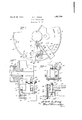
- Figure 1 is an end elevation of a portion of a winch showing the pawl in full lines in inactive position, and in dotted lines in. active position;
- Figure 2 is a front elevation of these parts
- Figure 3 is a section on the line 3-3 of Figure 1, and
- Figure 4 is a section on the line 4-4 of Figure 1.
- the side frame element has formed integral with it the bearing block 11, in which is mounted the Hubs 13 keyed to this shaft carry the spool sleeve 14.
- the hub shown in the drawings has formed integral with it the flange 15 and brake drum 16.
- lugs or teeth 17 have been cast and have been shown with inclined or slant faces although it will be appreciated that radial faces are wellknown in the art and are more usual in this connection.
- a web 18 is formed, in which are provided two bearing apertures.
- the holding elements comprise a pawl 19 and a trip 20.
- the pawl is mounted upon the pivot bolt 21 working in the lower of the bearing apertures in frame element 10. It will be observed that the necessary washers 22 and 24 as well as spacer 25 are provided.
- the toe of the pawl is adapted to engage the lugs cast on the inner face of the brake drum.
- the heel 26 of the pawl is apertured to support the pintle 27, which consists of a sleeve 28 and bolt 29.
- the pivot bolt 30 In the upper aperture in the web 18 is mounted the pivot bolt 30, upon which swings the trip 20, the required washers 31 and 32 as well as the spacer 33, being present.
- the trip swings freely from the pivot bolt and at its lower end is provided with a pedal 34 projecting beyond the rim of the brake drum,
- the trip is provided with a cam projection 35, defining two cam surfaces 36 and 37, both of which are designed to ride upon the sleeve 28 to lift the pawl.
- a cam projection 35 Between the cam projection 35 and the pedal 34 is a recess or pocket, in which the sleeve 28 is trapped when it is desired that the pawl be inactive.
- An inspection of Figure 1 of the drawings will demonstrate that so long as the sleeve 28 lies in thesaid pocket, the toe of the pawl 19 will be held elevated out of engagement with the lugs 17 (shown in full lines in said figure) and no holding of the winch spool will be effected.
- the spool is formed with a hub at the opposite side similar to the hub 13 carrying a flange similar to the flange 15.
- a gear of ring type is used, dish shaped, toothed exteriorly and provided with lugs similar to the lugs 17 on its inner face.
- a cast steel side frame similar to the frame element 10, is employed to support the opposite end of the spool shaft.
- the holding pawl may be transferred from the brake drum end to the gear end of the spool by reversing the relative positions of the trip and pawl. This is made possible by the proper design of elements forming these members as shown.
- a winch comprising a spool rotatably mounted between side frame elements, said spool having a dished end with holding lugs at its end, a holding device for engaging said lugs, mounted on a side frame element and comprising a pawl and a trip, the pawl and trip elements being symmetrically designed so that they may be reversed in position with respect to each other for the purpose of mounting them upon the opposite end of the drum.
- a holding device for a winch comprising a spool having lugs at its end and mounted between side frames, a pawl pivoted on the side frame and adapted to engage the lugs on the spool end when in active position and to clear said lugs when in inactive position, and a trip or latch mounted on the side frame for controlling said pawl, the pawl being pivoted intermediate its end defining a heel, and the trip or latch being provided with a projection and a pedal extension defining a pair of cam surfaces and a lock pocket, which cooperate with the heel of the pawl to switch the pawl from active to inactive position and maintain it inactive.
- a holding device for a winch comprising a spool mounted between side frames and provided with a dished end, lugs upon the inner face of the spool end, bearing apertures in the adjacent side frame, a pawl pivoted in one of said bearing apertures and cooperating with said lugs, and a trip or latch for said pawl pivoted in the other of said bearing apertures.
Landscapes
- Engineering & Computer Science (AREA)
- Mechanical Engineering (AREA)
- Braking Arrangements (AREA)
Description
March 29., 1932. YOUNG ta asmae WINCH HOLDING PAWL Filed Dec. 9. 1927 spool shaft 12.
Patented Mar. 29, 1932 UNITED STATES PATENT OFFICE FRANK L. YOUNG, OF WASHINGTON, DISTRICT OF COLUMBIA, ASSIGNOR T WILLIAM I). SHOEMAKER, OF WASHINGTON, DISTRICT OF COLUMBIA wmcn HOLDING PAWL This invention relates to a winch, and more particularly to a sub-combination of winch elements comprising a holding pawl.
It has for its object to provide a holding pawl for a winch, which will occupy a minimum of space, be easily operated, and be protected from injury. A further object is the improvement of the details of construction of such a pawl, and the selection of elements which will render the pawl and control therefor transferable to the opposite side of the winch. A still further object is the provision of simple means for maintaining a holding pawl inactive when desired.
Other objects and advantages of the invention will hereinafter appear in the following description and the novel features thereof will be particularly pointed out in the appended claims.
Like letters of reference indicate like parts throughout the several figures of the drawings, in which Figure 1 is an end elevation of a portion of a winch showing the pawl in full lines in inactive position, and in dotted lines in. active position;
Figure 2 is a front elevation of these parts;
Figure 3 is a section on the line 3-3 of Figure 1, and
Figure 4 is a section on the line 4-4 of Figure 1.
Referring to Figures 1 and 2, the side frame element has formed integral with it the bearing block 11, in which is mounted the Hubs 13 keyed to this shaft carry the spool sleeve 14. The hub shown in the drawings has formed integral with it the flange 15 and brake drum 16.
The parts just referred to it will be understood are well known details of the winch attachment for tractors covered by the patents of Harry S. Myers, identified by number and date as follows: Nos. 1,411,061, March 28, 1922, 1,413,287, April 12, 1922, 1,413,421, April 18, 1922, 1,414,038, April 25, 1922, 1,418,265, May 30, 1922, and 1,557,470, October 13, 1925.
Upon the inner face of the brake drum 16, lugs or teeth 17 have been cast and have been shown with inclined or slant faces although it will be appreciated that radial faces are wellknown in the art and are more usual in this connection. Upon the cast steel side frame member 10 a web 18 is formed, in which are provided two bearing apertures.
The holding elements comprise a pawl 19 and a trip 20. The pawl is mounted upon the pivot bolt 21 working in the lower of the bearing apertures in frame element 10. It will be observed that the necessary washers 22 and 24 as well as spacer 25 are provided. As shown on the drawings, the toe of the pawl is adapted to engage the lugs cast on the inner face of the brake drum. The heel 26 of the pawl is apertured to support the pintle 27, which consists of a sleeve 28 and bolt 29.
In the upper aperture in the web 18 is mounted the pivot bolt 30, upon which swings the trip 20, the required washers 31 and 32 as well as the spacer 33, being present. The trip swings freely from the pivot bolt and at its lower end is provided with a pedal 34 projecting beyond the rim of the brake drum,
to be engaged by the toe of an operators shoe when it is desirable to shift the pawl from active to inactive position or vice versa, as will be hereinafter set forth.
Intermediate its ends, the trip is provided with a cam projection 35, defining two cam surfaces 36 and 37, both of which are designed to ride upon the sleeve 28 to lift the pawl. Between the cam projection 35 and the pedal 34 is a recess or pocket, in which the sleeve 28 is trapped when it is desired that the pawl be inactive. An inspection of Figure 1 of the drawings will demonstrate that so long as the sleeve 28 lies in thesaid pocket, the toe of the pawl 19 will be held elevated out of engagement with the lugs 17 (shown in full lines in said figure) and no holding of the winch spool will be effected.
But when the pawl and trip are in the position shown in dotted lines, the toe end of the pawl, being relatively heavy, will fall into contact with the inner face of the brake drum and the heel end lifted, when the sleeve 28 will ride up the cam surface 36 and swing the trip to the position shown in dotted lines when it barely projects beyond the outer surfaceof the brake drum. When the toe of the pawl is lifted by the passage of a lug 17 under it in the operation of the winch, the heel will be lowered and the trip under its influence will swing slightly. In this condition of the parts the pawl is active.
If it is desired to make the pawl inactive, it is only necessary to push the pedal 34 from its position shown in dotted lines toward its full line position, when the pawl will be lifted high of the lugs as the sleeve 28 rides down the cam surface 36 and around the point of the cam projection 35 into the pocketed position in which it is shown in full lines in the figure.
When it is desired to change the pawl position from inactive to active, a movement of the trip from its full line positiontoward its dotted line position will cause the sleeve 28 to ride down the cam surface 87 and round the cam projection 35 into its uncontrolled position in contact with the cam surface 36.
The construction of parts is such that a certain reversibility is secured. According to the design of winch, of which this holding device is av component part, the spool is formed with a hub at the opposite side similar to the hub 13 carrying a flange similar to the flange 15. Instead of the brake drum 16, a gear of ring type is used, dish shaped, toothed exteriorly and provided with lugs similar to the lugs 17 on its inner face. A cast steel side frame, similar to the frame element 10, is employed to support the opposite end of the spool shaft.
It will be appreciated that the holding pawl may be transferred from the brake drum end to the gear end of the spool by reversing the relative positions of the trip and pawl. This is made possible by the proper design of elements forming these members as shown.
Changes in the details of construction may be resorted to without departing from the spirit of the invention as defined by the appended claims.
Having described the invention, what is claimed is:
1. In a winch comprising a spool rotatably mounted between side frame elements, said spool having a dished end with holding lugs at its end, a holding device for engaging said lugs, mounted on a side frame element and comprising a pawl and a trip, the pawl and trip elements being symmetrically designed so that they may be reversed in position with respect to each other for the purpose of mounting them upon the opposite end of the drum.
2. In a holding device for a winch comprising a spool having lugs at its end and mounted between side frames, a pawl pivoted on the side frame and adapted to engage the lugs on the spool end when in active position and to clear said lugs when in inactive position, and a trip or latch mounted on the side frame for controlling said pawl, the pawl being pivoted intermediate its end defining a heel, and the trip or latch being provided with a projection and a pedal extension defining a pair of cam surfaces and a lock pocket, which cooperate with the heel of the pawl to switch the pawl from active to inactive position and maintain it inactive.
3. In a holding device for a winch comprising a spool mounted between side frames and provided with a dished end, lugs upon the inner face of the spool end, bearing apertures in the adjacent side frame, a pawl pivoted in one of said bearing apertures and cooperating with said lugs, and a trip or latch for said pawl pivoted in the other of said bearing apertures.
4. The combination of claim 3 wherein the pawl and trip are symmetrical so that they may be demount-ed from the side frame and mounted upon the other side frame of the winch in relatively reversed positions.
In testimony whereof I aflix my signature.
FRANK L. YOUNG.
Priority Applications (1)
| Application Number | Priority Date | Filing Date | Title |
|---|---|---|---|
| US238841A US1851796A (en) | 1927-12-09 | 1927-12-09 | Winch holding pawl |
Applications Claiming Priority (1)
| Application Number | Priority Date | Filing Date | Title |
|---|---|---|---|
| US238841A US1851796A (en) | 1927-12-09 | 1927-12-09 | Winch holding pawl |
Publications (1)
| Publication Number | Publication Date |
|---|---|
| US1851796A true US1851796A (en) | 1932-03-29 |
Family
ID=22899548
Family Applications (1)
| Application Number | Title | Priority Date | Filing Date |
|---|---|---|---|
| US238841A Expired - Lifetime US1851796A (en) | 1927-12-09 | 1927-12-09 | Winch holding pawl |
Country Status (1)
| Country | Link |
|---|---|
| US (1) | US1851796A (en) |
-
1927
- 1927-12-09 US US238841A patent/US1851796A/en not_active Expired - Lifetime
Similar Documents
| Publication | Publication Date | Title |
|---|---|---|
| US2613046A (en) | Fishing reel | |
| US1851796A (en) | Winch holding pawl | |
| KR101695753B1 (en) | Bushing rotation device, and ladle having the same | |
| US2194228A (en) | One-way clutch | |
| US1508446A (en) | Sprocket wheel and chain | |
| US2295224A (en) | Brake structure | |
| US2447574A (en) | Safety cranking means for hand wheels of machine spindles and the like | |
| US2017484A (en) | Shade roller operating mechanism | |
| US1957943A (en) | Differential chain hoist | |
| US1834222A (en) | Clutch control device | |
| US1414884A (en) | Clutch lock | |
| US2029127A (en) | Power lift clutch mechanism | |
| US2156362A (en) | Clutch | |
| US2205149A (en) | Loom letoff | |
| US1347211A (en) | Attachment for rope-blocks | |
| US1798499A (en) | Disk brake | |
| US1758216A (en) | Traction driving mechanism | |
| US256736A (en) | Curtain-fixture | |
| US1512925A (en) | Hand brake for railway cars | |
| US1512478A (en) | Pump jack | |
| GB356502A (en) | Improvements in bearings | |
| US279304A (en) | Automatic brake for hoisting-machines | |
| US2279004A (en) | Ratchet lever | |
| US1781195A (en) | Reversible cable drum | |
| US519294A (en) | Apparatus |